EP0609036A1 - Steuerungs- und Betriebssystem - Google Patents
Steuerungs- und Betriebssystem Download PDFInfo
- Publication number
- EP0609036A1 EP0609036A1 EP94300479A EP94300479A EP0609036A1 EP 0609036 A1 EP0609036 A1 EP 0609036A1 EP 94300479 A EP94300479 A EP 94300479A EP 94300479 A EP94300479 A EP 94300479A EP 0609036 A1 EP0609036 A1 EP 0609036A1
- Authority
- EP
- European Patent Office
- Prior art keywords
- control
- operating system
- valve
- further characterised
- valve mechanism
- Prior art date
- Legal status (The legal status is an assumption and is not a legal conclusion. Google has not performed a legal analysis and makes no representation as to the accuracy of the status listed.)
- Withdrawn
Links
- 238000010438 heat treatment Methods 0.000 claims abstract description 59
- 230000007246 mechanism Effects 0.000 claims abstract description 35
- 238000009434 installation Methods 0.000 claims abstract description 27
- 239000012530 fluid Substances 0.000 description 4
- XLYOFNOQVPJJNP-UHFFFAOYSA-N water Substances O XLYOFNOQVPJJNP-UHFFFAOYSA-N 0.000 description 4
- 230000005540 biological transmission Effects 0.000 description 3
- 238000005265 energy consumption Methods 0.000 description 3
- 238000010586 diagram Methods 0.000 description 2
- 230000003213 activating effect Effects 0.000 description 1
- 230000000295 complement effect Effects 0.000 description 1
- 238000006073 displacement reaction Methods 0.000 description 1
- 238000009413 insulation Methods 0.000 description 1
- 230000007257 malfunction Effects 0.000 description 1
- 238000012544 monitoring process Methods 0.000 description 1
- 239000004065 semiconductor Substances 0.000 description 1
- 239000000126 substance Substances 0.000 description 1
Images
Classifications
-
- F—MECHANICAL ENGINEERING; LIGHTING; HEATING; WEAPONS; BLASTING
- F24—HEATING; RANGES; VENTILATING
- F24D—DOMESTIC- OR SPACE-HEATING SYSTEMS, e.g. CENTRAL HEATING SYSTEMS; DOMESTIC HOT-WATER SUPPLY SYSTEMS; ELEMENTS OR COMPONENTS THEREFOR
- F24D19/00—Details
- F24D19/10—Arrangement or mounting of control or safety devices
- F24D19/1006—Arrangement or mounting of control or safety devices for water heating systems
- F24D19/1009—Arrangement or mounting of control or safety devices for water heating systems for central heating
- F24D19/1015—Arrangement or mounting of control or safety devices for water heating systems for central heating using a valve or valves
Definitions
- the present invention relates to a control and operating system and, in particular, to the control and operation of central heating installations or the like.
- the invention will find particular application in domestic, industrial and commercial locations.
- Conventional central heating installations generally include a main flow pipe carrying newly heated fluid from the heating appliance and a main return pipe carrying cooler fluid back to the heating appliance for re-heating.
- Each individual heating panel is connected at it's inlet via a branch connection to the main flow pipe and at it's outlet via another branch connection to the main return pipe.
- a heating panel is defined as any fluid filled unit where the primary purpose of which is to radiate heat such as a radiator, towel rail, underfloor heater etc.
- Two gate valves are normally provided on each panel, one at the inlet side generally used to turn the heating panel on or off, and one on the outlet side which could equally be used to turn the heating panel on or off but is more generally used to adjust the flow rate and thus balance the system.
- the present invention has been made in order to overcome the abovementioned disadvantages.
- the principal objective of the invention is to reduce energy consumption by providing, at an economic cost, a control and operating system for central heating installations which allows individual heating panels to be quickly and conveniently turned on or off from a single or multiple remote locations. Thus heating only those rooms which are in use or about to be used will be less tedious, less time consuming and more convenient.
- Energy consumption in a wet central heating installation is directly proportional to the volume of water heated by the heating appliance.
- volume of water heated by the heating appliance By limiting the volume of fluid to be heated to a minimum, i.e. to that required to heat only the rooms being used or about to be used, substantial savings will be made.
- a control and operating system for a central heating installation comprising a plurality of valve mechanisms for mounting in or on the central heating installation, a plurality of electromechanical devices each adapted to be connected to a respective valve mechanism and a control device capable of independently controlling each valve mechanism by means of the electromechanical devices.
- control device is capable of independently controlling the on/off status of a plurality of heating panels in a central heating installation.
- the on/off status of such heating panels may be discretely or continuously controllable between the on and off position.
- the valve mechanism may include a ball type valve, a solenoid operated valve or any other suitable valve.
- the valve mechanism will preferably be capable of changing from fully open to fully closed with only short rotation and/or longitudinal or lateral movement and will preferably be capable of manual override movement as a fail-safe against power failure or electromechanical malfunction.
- valve mechanism will preferably be located on the flow inlet pipe to the heating panel but could satisfactorily be located on the outlet pipe from the heating panel. Equally the valve mechanism could be incorporated within the heating panel itself immediately adjacent to the inlet or outlet.
- valve mechanisms could be located adjacent to the manifold itself on either the flow or return pipes from each individual heating panel or at any convenient location on either the flow or return pipes between the manifold and the heating panel.
- the electromechanical device may include gears and may be connected to the valve mechanism by a gear-type arrangement.
- Any suitable electromechanical device may be used to achieve the desired rotary and/or longitudinal or lateral movement of the valve mechanism.
- the electromechanical device used may incorporate suitable and appropriate gearing.
- the desired rotary and/or longitudinal or lateral movement of the valve mechanism may be achieved by modifying existing geared servos.
- a receiver device may be incorporated within the electromechanical device to enable the electromechanical device to be activated, and hence operate the valve mechanism, by a corresponding transmitter. It will be appreciated that any suitable transmission means may be used such as radio infrared or sonar.
- each electromechanical device will have a powered override facility.
- the control device preferably includes a control panel which may be operated manually, by remote control or otherwise.
- the control device may be programmable.
- a valve mechanism and electromechanical device is provided for each heating panel in the central heating installation.
- control device includes a transmitter and the electromechanical device includes a receiver and control of the valve mechanism is achieved by means of electromagnetic transmission between the transmitter and the receiver.
- the control panel for the hard-wired system may take the form of a fixed panel mounted at any location within the building convenient for the user. Repeater panels may be mounted at other locations within the building.
- the control panel for the transmitter and receiver systems may be mounted in a fixed position or be completely mobile for use at any location in the building. Thus, the control panel may be adapted for remote operation of the control device. Any suitable transmitter and receiver system may be used such as radio, infrared or sonar.
- Control may also be achieved by a combination of a fixed panel and a mobile infrared hand set.
- Push button, rotary or the like switches may be provided on the control panel to permit a variety of valve operations, from fully open through a sequence of stages using limit switches or the like to fully closed.
- the control system preferably includes thermostatic controls preferably at one or each of the valve mechanism locations so that the temperature required at one or each heating panel site may be selected at the control panel.
- the thermostatic controls will preferably include a frost and/or a predetermined minimum temperature setting which, when reached, overrides all other signals and activates the valve mechanism passing a complementary and concurrent signal, via the control panel, to activate the heating appliance.
- the control panel may include display means such as a digital clock and L.E.D.'s or the like indicating the current status of each valve mechanism.
- the control panel may preferably include a programming facility so that the user can program each individual heating panel to operate for a given period at a predetermined time and, if required, at a predetermined temperature.
- the simplest form of the invention provides for a mechanised rotating ball valve to be installed on the flow inlet to each individual heating panel.
- the ball valve is operated via a simple hard-wired low voltage circuit to a master control panel. The user will then be able to control each individual heating panel at the touch of a button rather than having to visit each heating panel site to operate conventional gate valves manually.
- valve assembly Installation of the valve assembly is easily carried out without draining down the central heating installation. BY using rubber bungs or the like inserted in the outlet of the header tank and the expansion pipe; air and water are effectively prevented from entering the system thus allowing a pipe to be severed without loss of water.
- control gear is then simply clipped onto the adjacent pipework and located over a square or splined head connected directly to the rotating valve.
- the control system is preferably operated on a 6 to 9 volt DC supply.
- a very small cable may be used such as bell wire or telephone wire size. This type of wire can easily be be be hidden around carpet edges thus obviating the need for floor boards and carpets to be taken up during installation of the wiring.
- the electrical circuitry may be connected to the control mechanism by a simple spiggot connector or the like into a socket or the like provided within the control mechanism.
- a simple spiggot connector or the like may be provided to connect each individual heating panel on the system via a spiggot connector or the like to the appropriate port.
- a central heating installation including a control and operating system of the invention.
- a light weight four core cable may be used to transmit power an dcontrol signals to all the valve actuators in the building.
- this cable would be of similar type to that used for internal telephone wiring.
- the four cores could be used as follows: 2 cores for low voltage DC power (maximum 48 volts). 2 cores for duplex control signals.
- a digital communication protocol may be employed which would allow two way communication between any remote actuator and the control unit.
- Each actuator may have its own unique address, internally preset, so that the control unit could demand the attention of any particular actuator before commencing a dialogue.
- the communication protocol may be designed in such a way as to allow all the actuators to be connected in parallel across the four cores of the cable without interference, thus simplifying installation. Insulation displacement connectors in each actuator would further simplify the installation.
- Each actuator may contain a temperature measuring device capable of monitoring the ambient temperature and relaying this information back to the control unit upon request.
- the control unit could implement a continuous polling scheme to monitor the temperatures of all the rooms in the building and use this information to maintain a precise temperature in each room without the need for an additional thermostatic valve.
- the control unit may be programmed so that for example heatin gunit valves will be operated at least once per day outside the heating season. This would prevent the build up of chemical deposits on the valve mechanism. Such deposits are known to be troublesome to existing valve mechanisms which are traditionally left stationary during the summer months.
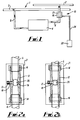
- a central heating installation 1 comprises a main flow pipe 2, a main return pipe 3, one or more heating panels 4 and inlet and outlet pipes 6, 8 leading into and out from heating panel 4.
- the control system 10 includes a valve body 12 which is inserted at some location along the inlet pipe 6 and secured by means of nuts 14.
- An electromechanical device 16 is located adjacent to the valve body 12 and may be secured to the pipes at either end of the valve body 12 or to the pipe body 12 itself.
- valve body One type of valve body is shown in Figures 2a and 2b wherein a bored out ball 18 is mounted in the valve body 12.
- a bore 20 extends through the ball such that when the valve 21 is in the open position the bore 20 extends substantially parallel to the longitudinal length of the valve body 12.
- the ball 18 is rotated within the valve body 12 by about 90 degrees so that the bore 20 extends approximately at right angles to the longitudinal length of the valve body 12.
- the rotation is achieved by means of a cog, spline, or square head 17 which is fixedly connected via shaft 19 to the ball 18.
- the cog, spline or square head may be turned using a stepper motor or the like.
- the electromechanical device 16 includes appropriate gears and circuitry to allow the valve 21 to be operated as required.
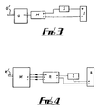
- FIGS 3 and 4 illustrate possible ways of operating the valve.
- a low voltage dc supply B such as a 6 volt battery is used to drive a motor M.
- the motor M may directly operate the ball valve via spindle M' or the valve may be operated indirectly through gear box G connected to motor N such as by using a stepped motor N such as by using a stepped motor or the like.
- spindle or cog G' rotates the ball valve.
- Switch S is provided along the positive supply input to enable the supply to be switched on or off as required. Any suitable type of mechanical or detector type switching mechanisms may be used.
- a receiver device R may be incorporated so that operation of the motor M is achieved by activating the receiver device R, for example using a corresponding transmitter T (not shown).
- Rotation of the ball valve may be achieved by modifying existing geared servos.
- a control panel 22 is mounted at a suitable accessible location remote from the valve 21 and electromechanical device 16.
- the control panel 22 is hard-wired 24 to the electromechanical device 16. It will be appreciated however that any suitable transmission means may be used such as radio, infrared or sonic control.
- any suitable valve mechanism may be used.
- Any suitable electromechanical device may be used and preferably the circuitry includes semiconductor chips to facilitate miniaturisation of the device.
- the control panel may be operated by remote control or manually.
Landscapes
- Engineering & Computer Science (AREA)
- Physics & Mathematics (AREA)
- Thermal Sciences (AREA)
- Chemical & Material Sciences (AREA)
- Combustion & Propulsion (AREA)
- Mechanical Engineering (AREA)
- General Engineering & Computer Science (AREA)
- Steam Or Hot-Water Central Heating Systems (AREA)
Applications Claiming Priority (2)
| Application Number | Priority Date | Filing Date | Title |
|---|---|---|---|
| GB939301522A GB9301522D0 (en) | 1993-01-26 | 1993-01-26 | Control and operating system |
| GB9301522 | 1993-01-26 |
Publications (1)
| Publication Number | Publication Date |
|---|---|
| EP0609036A1 true EP0609036A1 (de) | 1994-08-03 |
Family
ID=10729350
Family Applications (1)
| Application Number | Title | Priority Date | Filing Date |
|---|---|---|---|
| EP94300479A Withdrawn EP0609036A1 (de) | 1993-01-26 | 1994-01-21 | Steuerungs- und Betriebssystem |
Country Status (2)
| Country | Link |
|---|---|
| EP (1) | EP0609036A1 (de) |
| GB (2) | GB9301522D0 (de) |
Cited By (1)
| Publication number | Priority date | Publication date | Assignee | Title |
|---|---|---|---|---|
| EP1473608A2 (de) | 2003-04-16 | 2004-11-03 | HAWE Hydraulik GmbH & Co. KG | Elektrohydraulische Steuervorrichtung und Anschlussgehäuse für eine elektrohydraulische Steuervorrichtung |
Citations (4)
| Publication number | Priority date | Publication date | Assignee | Title |
|---|---|---|---|---|
| EP0014535A1 (de) * | 1979-01-23 | 1980-08-20 | Plympton Patents Limited | Steuervorrichtungen für Heizsysteme |
| EP0029922A2 (de) * | 1979-12-04 | 1981-06-10 | Hans-Joachim Frei | Heizungssteuerungseinrichtung |
| EP0282255A2 (de) * | 1987-03-07 | 1988-09-14 | Cambridge Instruments Limited | Steuersysteme |
| EP0375826A1 (de) * | 1988-12-30 | 1990-07-04 | FIMCIM S.r.l. | Kugelventil |
Family Cites Families (1)
| Publication number | Priority date | Publication date | Assignee | Title |
|---|---|---|---|---|
| GB2258714B (en) * | 1991-08-13 | 1995-05-24 | Drayton Controls | Fluid-flow control apparatus |
-
1993
- 1993-01-26 GB GB939301522A patent/GB9301522D0/en active Pending
-
1994
- 1994-01-21 GB GB9401178A patent/GB2274501A/en not_active Withdrawn
- 1994-01-21 EP EP94300479A patent/EP0609036A1/de not_active Withdrawn
Patent Citations (4)
| Publication number | Priority date | Publication date | Assignee | Title |
|---|---|---|---|---|
| EP0014535A1 (de) * | 1979-01-23 | 1980-08-20 | Plympton Patents Limited | Steuervorrichtungen für Heizsysteme |
| EP0029922A2 (de) * | 1979-12-04 | 1981-06-10 | Hans-Joachim Frei | Heizungssteuerungseinrichtung |
| EP0282255A2 (de) * | 1987-03-07 | 1988-09-14 | Cambridge Instruments Limited | Steuersysteme |
| EP0375826A1 (de) * | 1988-12-30 | 1990-07-04 | FIMCIM S.r.l. | Kugelventil |
Cited By (2)
| Publication number | Priority date | Publication date | Assignee | Title |
|---|---|---|---|---|
| EP1473608A2 (de) | 2003-04-16 | 2004-11-03 | HAWE Hydraulik GmbH & Co. KG | Elektrohydraulische Steuervorrichtung und Anschlussgehäuse für eine elektrohydraulische Steuervorrichtung |
| EP1473608A3 (de) * | 2003-04-16 | 2005-05-04 | HAWE Hydraulik GmbH & Co. KG | Elektrohydraulische Steuervorrichtung und Anschlussgehäuse für eine elektrohydraulische Steuervorrichtung |
Also Published As
| Publication number | Publication date |
|---|---|
| GB9401178D0 (en) | 1994-03-16 |
| GB9301522D0 (en) | 1993-03-17 |
| GB2274501A (en) | 1994-07-27 |
Similar Documents
| Publication | Publication Date | Title |
|---|---|---|
| US4824012A (en) | Air flow damper control system | |
| US6895985B2 (en) | Smart device and system for improved domestic use and saving of water | |
| US6179213B1 (en) | Universal accessory for timing and cycling heat, ventilation and air conditioning energy consumption and distribution systems | |
| US4974636A (en) | Computerized water faucet | |
| US5810245A (en) | Method and apparatus for controlling air flow in a structure | |
| US6701951B1 (en) | Manual to electronic automatic valve conversion apparatus | |
| GB2216293A (en) | Radiator valve control apparatus | |
| US3882928A (en) | Building heating and cooling system | |
| EP0609036A1 (de) | Steuerungs- und Betriebssystem | |
| EP1944535B1 (de) | Wärmekonditionierungssystem, Verteilereinheit und Ventil für dieses System sowie Verfahren zur Wärmekonditionierung eines Gebäudes mit diesem System | |
| EP0982642B1 (de) | Verfahren zur Steuerung von Elektro-Installationen in Gebäuden und eine Steuerungsanordnung für die Steuerung von Elektro-Installationen in Gebäuden | |
| US20200037400A1 (en) | Electric fluid heating system and method of use thereof | |
| CZ130297A3 (en) | Control device for heating equipment | |
| JP6092855B2 (ja) | 暖房、換気および/または空調装置並びにそれを用いたキット | |
| JPH08166159A (ja) | 換気扇コントロールシステム | |
| US4718599A (en) | Control systems | |
| JP2000240951A (ja) | 床暖房制御装置 | |
| KR20050103855A (ko) | 건물의 냉난방제어시스템 | |
| RU2202076C1 (ru) | Система кондиционирования воздуха | |
| KR200309211Y1 (ko) | 냉난방장치의 소켓형 중앙제어시스템 | |
| US9016313B2 (en) | Regulation system | |
| KR100669653B1 (ko) | 각방 난방장치의 통합 제어 방법 및 시스템 | |
| GB2342429A (en) | Flow control for boiler of central heating/hot water system | |
| KR200300073Y1 (ko) | 전력선을 이용한 온수분배기의 제어시스템 | |
| GB2050704A (en) | Control apparatus |
Legal Events
| Date | Code | Title | Description |
|---|---|---|---|
| PUAI | Public reference made under article 153(3) epc to a published international application that has entered the european phase |
Free format text: ORIGINAL CODE: 0009012 |
|
| AK | Designated contracting states |
Kind code of ref document: A1 Designated state(s): AT BE CH DE DK FR IT LI NL SE |
|
| STAA | Information on the status of an ep patent application or granted ep patent |
Free format text: STATUS: THE APPLICATION IS DEEMED TO BE WITHDRAWN |
|
| 18D | Application deemed to be withdrawn |
Effective date: 19950204 |