EP0014573A1 - Brennkammer für Gasturbine - Google Patents
Brennkammer für Gasturbine Download PDFInfo
- Publication number
- EP0014573A1 EP0014573A1 EP80300298A EP80300298A EP0014573A1 EP 0014573 A1 EP0014573 A1 EP 0014573A1 EP 80300298 A EP80300298 A EP 80300298A EP 80300298 A EP80300298 A EP 80300298A EP 0014573 A1 EP0014573 A1 EP 0014573A1
- Authority
- EP
- European Patent Office
- Prior art keywords
- combustion chamber
- segment
- wall
- annular
- baffle
- Prior art date
- Legal status (The legal status is an assumption and is not a legal conclusion. Google has not performed a legal analysis and makes no representation as to the accuracy of the status listed.)
- Granted
Links
Images

Classifications
-
- F—MECHANICAL ENGINEERING; LIGHTING; HEATING; WEAPONS; BLASTING
- F23—COMBUSTION APPARATUS; COMBUSTION PROCESSES
- F23R—GENERATING COMBUSTION PRODUCTS OF HIGH PRESSURE OR HIGH VELOCITY, e.g. GAS-TURBINE COMBUSTION CHAMBERS
- F23R3/00—Continuous combustion chambers using liquid or gaseous fuel
- F23R3/02—Continuous combustion chambers using liquid or gaseous fuel characterised by the air-flow or gas-flow configuration
- F23R3/04—Air inlet arrangements
- F23R3/06—Arrangement of apertures along the flame tube
- F23R3/08—Arrangement of apertures along the flame tube between annular flame tube sections, e.g. flame tubes with telescopic sections
-
- F—MECHANICAL ENGINEERING; LIGHTING; HEATING; WEAPONS; BLASTING
- F23—COMBUSTION APPARATUS; COMBUSTION PROCESSES
- F23R—GENERATING COMBUSTION PRODUCTS OF HIGH PRESSURE OR HIGH VELOCITY, e.g. GAS-TURBINE COMBUSTION CHAMBERS
- F23R3/00—Continuous combustion chambers using liquid or gaseous fuel
- F23R3/002—Wall structures
-
- F—MECHANICAL ENGINEERING; LIGHTING; HEATING; WEAPONS; BLASTING
- F23—COMBUSTION APPARATUS; COMBUSTION PROCESSES
- F23R—GENERATING COMBUSTION PRODUCTS OF HIGH PRESSURE OR HIGH VELOCITY, e.g. GAS-TURBINE COMBUSTION CHAMBERS
- F23R3/00—Continuous combustion chambers using liquid or gaseous fuel
- F23R3/42—Continuous combustion chambers using liquid or gaseous fuel characterised by the arrangement or form of the flame tubes or combustion chambers
- F23R3/60—Support structures; Attaching or mounting means
Definitions
- This invention relates to a combustion chamber for a gas turbine engine and more particularly to a double-wall combustion chamber configuration providing a flow path for convectively cooling the combustion chamber wall.
- Cylindrical, step-liner combustion chambers for gas turbines are well known.
- the step-liner configuration defines cylindrical segments extending axially with each downstream segment having a slightly larger diameter than the immediately preceding segment of the combustion chamber and generally with the leading edge of the larger diameter downstream segment overlapping the terminal edge of the upstream segment to define an annular, axially extending airflow path between adjacent segments.
- the adjacent segments are supported in such configuration by support means extending generally radially between the overlapping portions thereof permitting an entry for cooling air, flowing exteriorly of the combustion chamber, to enter the chamber through the annular passage.
- Such cooling air while flowing over the outer surface of the upstream segment, tends to cool the upstream segment by convectively removing the heat therefrom, and, upon entering the annular passage, continues to flow along the inside surface of the downstream segment to form a layer of barrier or film cooling air, protecting the inner surface of the combustion chamber from the combustion gases therewithin.
- the cooling provided the downstream segment by such air is not as dependent upon the air having a low temperature as it is upon the air maintaining a protective layer.
- a double-wall step-liner combustion chamber such as shown in U.S. Patent No. 3,702,058, wherein an outer annular sleeve or baffle encircled each cylindrical segment of the chamber and was maintained in annular-spaced relation thereabout by an annular corrugated member or wiggle strip, with all components being assembled and welded together to provide an integral structure.
- annular baffle member encircles each cylindrical segment of the step-liner combustion chamber with each baffle member maintained in radially spaced relation to the segment by leaf-spring support members permitting the outer chamber wall to expand both axially and radially without affecting the annular baffle or inducing stress factors therein.
- the outer surface of each cylindrical segment of the combustion chamber except in the areas contacted by the leaf spring, has outwardly projecting dimples or projections which induced turbulence in the cooling air flowing in the annular space between the baffle and chamber wall and which also increase the exposed surface area of the chamber wall to increase the heat transfer between the chamber and the air flowing in the passage.
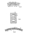
- the combustion chamber 10 of the present invention is formed of a plurality of cylindrical segments 12 with the inlet or upstream segment having a diameter less than the next adjacent downstream segment which, in turn, has a diameter less than the next adjacent downstream segment.
- An annular transition ring 13 is interposed between adjacent cylindrical segments which, in axial cross section, provides a generally U-shaped configuration, with one leg 14 thereof attached, as by welding, to the terminal edge of the upstream segment and the opposite leg 15 attached, also by welding, to the leading edge of the downstream segment.
- the bight or web portion 16 of the annular ring defines a plurality of apertures 17 (more clearly shown in Figs. 3 and 4) permitting cooling air to enter the downstream chamber at the upstream edge of each segment and, as directed by the openings 17, and flow along the inner face of each segment to provide a film of air thereover.
- Such configuration provides a step-liner cylindrical combustion chamber.
- each baffle member 20 encircle each combustion chamber segment 12 and are maintained in radi- a ally uniform spaced relation therewith to define an annular cooling airflow path 19 between the baffle and the outer surface of the segment. More particularly, each baffle member 20 defines an entry or throat area 22 at its upstream end defined by a slightly belled leading edge 24 terminating in a portion 26 stepped outwardly from the axially extending mid-section 28. The terminal portion of each baffle member defines an outwardly stepped axially extending portion 30 terminating in a further outwardly stepped marginal edge 32 which overlaps, in radially close proximity, the outer leg 15 of the annular transition ring 13 to the next adjacent cylindrical segment.
- cooling air is directed into the annular space 19, between the baffle member and the cylindrical segment of the combustion chamber and upon exiting is directed into the opening 17 of the annular transition ring to flow along the inside wall of the next adjacent segment as described.
- each baffle member 20 is maintained in annular-spaced relation to the outer surface of each cylindrical segment by an annular row of a plurality of leaf-spring supports 36.
- Each leaf spring support defines a mid-portion 37 attached to the inner face of the baffle member (and as seen in Figs. 1 and 2, two such annular rows are provided and in axial alignment with the outwardly stepped portions adjacent leading and trailing edges) and opposed depending downwardly, outwardly extending arms 38 terminating in a rounded bearing surface 39 freely contacting the outer surface of the combustion chamber segment and with the arms 38 normally biasing the baffle 20 to a radially outer position to maintain the annular space 19 between the baffle and the combustion chamber wall.
- each combustion chamber segment defines a pattern of outwardly projecting pins or dimples 40.
- pins preferably do not extend the full radial width of the annular passage 19, but do project sufficiently into the cooling airflow path to induce turbulent flow.
- pins 40 also increase the surface area of the combustion chamber segment exposed to the cooling air, with both effects increasing the convection cooling capacity of the air flowing through the annular space.
- the portion of the outer surface of each segment on which the spring arms 38 bear is maintained smooth as at 42 (clearly seen in Fig.
- a double-wall step-liner configuration is provided for a combustion chamber with the inner or combustion chamber wall free to expand or contract independently of and without inducing stress into the outer air flow baffle, thereby improving the cooling effectiveness of the exteriorly flowing air without inducing failure- causing stresses in the assembly.
Landscapes
- Engineering & Computer Science (AREA)
- Chemical & Material Sciences (AREA)
- Combustion & Propulsion (AREA)
- Mechanical Engineering (AREA)
- General Engineering & Computer Science (AREA)
- Turbine Rotor Nozzle Sealing (AREA)
Applications Claiming Priority (2)
| Application Number | Priority Date | Filing Date | Title |
|---|---|---|---|
| US06/008,318 US4292810A (en) | 1979-02-01 | 1979-02-01 | Gas turbine combustion chamber |
| US8318 | 1979-02-01 |
Publications (2)
| Publication Number | Publication Date |
|---|---|
| EP0014573A1 true EP0014573A1 (de) | 1980-08-20 |
| EP0014573B1 EP0014573B1 (de) | 1985-06-19 |
Family
ID=21730968
Family Applications (1)
| Application Number | Title | Priority Date | Filing Date |
|---|---|---|---|
| EP80300298A Expired EP0014573B1 (de) | 1979-02-01 | 1980-02-01 | Brennkammer für Gasturbine |
Country Status (6)
| Country | Link |
|---|---|
| US (1) | US4292810A (de) |
| EP (1) | EP0014573B1 (de) |
| JP (1) | JPS55102836A (de) |
| AR (1) | AR220603A1 (de) |
| BR (1) | BR8000144A (de) |
| CA (1) | CA1130098A (de) |
Cited By (5)
| Publication number | Priority date | Publication date | Assignee | Title |
|---|---|---|---|---|
| GB2160964A (en) * | 1984-06-25 | 1986-01-02 | Gen Electric | Combustion chamber construction |
| GB2172987A (en) * | 1972-12-19 | 1986-10-01 | Gen Electric | Combustion chamber construction |
| FR2599429A1 (fr) * | 1986-05-28 | 1987-12-04 | Messerschmitt Boelkow Blohm | Structure-support pour une tuyere d'expansion de moteur-fusee. |
| EP2199681A1 (de) * | 2008-12-18 | 2010-06-23 | Siemens Aktiengesellschaft | Gasturbinenbrennkammer und Gasturbine |
| EP2144003A3 (de) * | 2008-07-10 | 2014-02-12 | United Technologies Corporation | Brennkammerwand für einen Gasturbinenmotor |
Families Citing this family (21)
| Publication number | Priority date | Publication date | Assignee | Title |
|---|---|---|---|---|
| US4887663A (en) * | 1988-05-31 | 1989-12-19 | United Technologies Corporation | Hot gas duct liner |
| DE19641957A1 (de) * | 1996-10-11 | 1998-04-16 | Abb Research Ltd | Vorrichtung zur Dichtung von Brennkammerziegeln |
| US6101814A (en) * | 1999-04-15 | 2000-08-15 | United Technologies Corporation | Low emissions can combustor with dilution hole arrangement for a turbine engine |
| US6279313B1 (en) | 1999-12-14 | 2001-08-28 | General Electric Company | Combustion liner for gas turbine having liner stops |
| US7464537B2 (en) * | 2005-04-04 | 2008-12-16 | United Technologies Corporation | Heat transfer enhancement features for a tubular wall combustion chamber |
| US8544277B2 (en) * | 2007-09-28 | 2013-10-01 | General Electric Company | Turbulated aft-end liner assembly and cooling method |
| US20090120093A1 (en) * | 2007-09-28 | 2009-05-14 | General Electric Company | Turbulated aft-end liner assembly and cooling method |
| US8128399B1 (en) * | 2008-02-22 | 2012-03-06 | Great Southern Flameless, Llc | Method and apparatus for controlling gas flow patterns inside a heater chamber and equalizing radiant heat flux to a double fired coil |
| US20100037620A1 (en) * | 2008-08-15 | 2010-02-18 | General Electric Company, Schenectady | Impingement and effusion cooled combustor component |
| US8438856B2 (en) | 2009-03-02 | 2013-05-14 | General Electric Company | Effusion cooled one-piece can combustor |
| US20100257863A1 (en) * | 2009-04-13 | 2010-10-14 | General Electric Company | Combined convection/effusion cooled one-piece can combustor |
| EP2270397A1 (de) | 2009-06-09 | 2011-01-05 | Siemens Aktiengesellschaft | Gasturbinenbrennkammer und Gasturbine |
| US20120208141A1 (en) * | 2011-02-14 | 2012-08-16 | General Electric Company | Combustor |
| US8745988B2 (en) * | 2011-09-06 | 2014-06-10 | Pratt & Whitney Canada Corp. | Pin fin arrangement for heat shield of gas turbine engine |
| US9897317B2 (en) | 2012-10-01 | 2018-02-20 | Ansaldo Energia Ip Uk Limited | Thermally free liner retention mechanism |
| US9194585B2 (en) * | 2012-10-04 | 2015-11-24 | United Technologies Corporation | Cooling for combustor liners with accelerating channels |
| US9228747B2 (en) * | 2013-03-12 | 2016-01-05 | Pratt & Whitney Canada Corp. | Combustor for gas turbine engine |
| WO2015117137A1 (en) * | 2014-02-03 | 2015-08-06 | United Technologies Corporation | Film cooling a combustor wall of a turbine engine |
| DE112020005627T5 (de) * | 2020-02-19 | 2022-09-08 | Mitsubishi Heavy Industries Engine & Turbocharger, Ltd. | Verbrenner und gasturbine |
| US12228081B2 (en) | 2020-08-25 | 2025-02-18 | Unison Industries, Llc | Air turbine starter with nozzle retention mechanism |
| US20250377108A1 (en) * | 2024-06-07 | 2025-12-11 | General Electric Company | Combustor for a turbine engine including an insulating member |
Citations (9)
| Publication number | Priority date | Publication date | Assignee | Title |
|---|---|---|---|---|
| CH213792A (de) * | 1939-09-29 | 1941-03-15 | Bbc Brown Boveri & Cie | Aus Metall hergestellte Brennkammer zur Erzeugung von Heiz- und Treibgasen mässiger Temperatur. |
| GB607824A (en) * | 1946-02-12 | 1948-09-06 | Lucas Ltd Joseph | Improvements relating to combustion chambers for prime movers |
| US2547619A (en) * | 1948-11-27 | 1951-04-03 | Gen Electric | Combustor with sectional housing and liner |
| US2617255A (en) * | 1947-05-12 | 1952-11-11 | Bbc Brown Boveri & Cie | Combustion chamber for a gas turbine |
| US2795108A (en) * | 1953-10-07 | 1957-06-11 | Westinghouse Electric Corp | Combustion apparatus |
| US3038309A (en) * | 1959-07-21 | 1962-06-12 | Gen Electric | Cooling liner for jet engine afterburner |
| CH501147A (de) * | 1968-10-28 | 1970-12-31 | Stal Laval Turbin Ab | Brennkammer für Gasturbinen |
| FR2045275A5 (de) * | 1969-04-02 | 1971-02-26 | United Aircraft Corp | |
| FR2121779A1 (de) * | 1971-01-13 | 1972-08-25 | Westinghouse Electric Corp |
Family Cites Families (12)
| Publication number | Priority date | Publication date | Assignee | Title |
|---|---|---|---|---|
| GB675300A (en) * | 1949-05-24 | 1952-07-09 | Rolls Royce | Improvements in or relating to exhaust ducting of gas-turbine engines |
| US2958194A (en) * | 1951-09-24 | 1960-11-01 | Power Jets Res & Dev Ltd | Cooled flame tube |
| US3420058A (en) * | 1967-01-03 | 1969-01-07 | Gen Electric | Combustor liners |
| DE1957147A1 (de) * | 1968-11-15 | 1970-06-04 | Rolls Royce | Flammrohr fuer Verbrennungsanlagen von Gasturbinentriebwerken |
| US3572031A (en) * | 1969-07-11 | 1971-03-23 | United Aircraft Corp | Variable area cooling passages for gas turbine burners |
| US3738106A (en) * | 1971-10-26 | 1973-06-12 | Avco Corp | Variable geometry combustors |
| US3851465A (en) * | 1973-04-06 | 1974-12-03 | Gen Motors Corp | Annular dilution zone combustor |
| US4109459A (en) * | 1974-07-19 | 1978-08-29 | General Electric Company | Double walled impingement cooled combustor |
| GB1550368A (en) * | 1975-07-16 | 1979-08-15 | Rolls Royce | Laminated materials |
| JPS5239974A (en) * | 1975-09-26 | 1977-03-28 | Hitachi Metals Ltd | Incinerator for fluid refuse |
| US4050241A (en) * | 1975-12-22 | 1977-09-27 | General Electric Company | Stabilizing dimple for combustion liner cooling slot |
| JPS5320008A (en) * | 1976-08-09 | 1978-02-23 | Hitachi Ltd | Gas turbine combustor |
-
1979
- 1979-02-01 US US06/008,318 patent/US4292810A/en not_active Expired - Lifetime
- 1979-12-28 CA CA342,707A patent/CA1130098A/en not_active Expired
-
1980
- 1980-01-10 BR BR8000144A patent/BR8000144A/pt unknown
- 1980-01-11 AR AR279606A patent/AR220603A1/es active
- 1980-01-31 JP JP949580A patent/JPS55102836A/ja active Pending
- 1980-02-01 EP EP80300298A patent/EP0014573B1/de not_active Expired
Patent Citations (9)
| Publication number | Priority date | Publication date | Assignee | Title |
|---|---|---|---|---|
| CH213792A (de) * | 1939-09-29 | 1941-03-15 | Bbc Brown Boveri & Cie | Aus Metall hergestellte Brennkammer zur Erzeugung von Heiz- und Treibgasen mässiger Temperatur. |
| GB607824A (en) * | 1946-02-12 | 1948-09-06 | Lucas Ltd Joseph | Improvements relating to combustion chambers for prime movers |
| US2617255A (en) * | 1947-05-12 | 1952-11-11 | Bbc Brown Boveri & Cie | Combustion chamber for a gas turbine |
| US2547619A (en) * | 1948-11-27 | 1951-04-03 | Gen Electric | Combustor with sectional housing and liner |
| US2795108A (en) * | 1953-10-07 | 1957-06-11 | Westinghouse Electric Corp | Combustion apparatus |
| US3038309A (en) * | 1959-07-21 | 1962-06-12 | Gen Electric | Cooling liner for jet engine afterburner |
| CH501147A (de) * | 1968-10-28 | 1970-12-31 | Stal Laval Turbin Ab | Brennkammer für Gasturbinen |
| FR2045275A5 (de) * | 1969-04-02 | 1971-02-26 | United Aircraft Corp | |
| FR2121779A1 (de) * | 1971-01-13 | 1972-08-25 | Westinghouse Electric Corp |
Cited By (6)
| Publication number | Priority date | Publication date | Assignee | Title |
|---|---|---|---|---|
| GB2172987A (en) * | 1972-12-19 | 1986-10-01 | Gen Electric | Combustion chamber construction |
| GB2160964A (en) * | 1984-06-25 | 1986-01-02 | Gen Electric | Combustion chamber construction |
| FR2599429A1 (fr) * | 1986-05-28 | 1987-12-04 | Messerschmitt Boelkow Blohm | Structure-support pour une tuyere d'expansion de moteur-fusee. |
| EP2144003A3 (de) * | 2008-07-10 | 2014-02-12 | United Technologies Corporation | Brennkammerwand für einen Gasturbinenmotor |
| EP2199681A1 (de) * | 2008-12-18 | 2010-06-23 | Siemens Aktiengesellschaft | Gasturbinenbrennkammer und Gasturbine |
| WO2010069663A1 (de) * | 2008-12-18 | 2010-06-24 | Siemens Aktiengesellschaft | Gasturbinenbrennkammer und gasturbine |
Also Published As
| Publication number | Publication date |
|---|---|
| US4292810A (en) | 1981-10-06 |
| BR8000144A (pt) | 1980-09-23 |
| EP0014573B1 (de) | 1985-06-19 |
| AR220603A1 (es) | 1980-11-14 |
| JPS55102836A (en) | 1980-08-06 |
| CA1130098A (en) | 1982-08-24 |
Similar Documents
| Publication | Publication Date | Title |
|---|---|---|
| EP0014573B1 (de) | Brennkammer für Gasturbine | |
| US4302941A (en) | Combuster liner construction for gas turbine engine | |
| US4773227A (en) | Combustion chamber with improved liner construction | |
| KR950003747B1 (ko) | 개스터빈 | |
| US3053283A (en) | Duct assemblies | |
| RU2406033C2 (ru) | Форсажная камера двухконтурного турбореактивного двигателя, двухконтурный турбореактивный двигатель и кронштейн стабилизатора пламени для форсажной камеры | |
| JP5475901B2 (ja) | 燃焼器ライナ及びガスタービンエンジンアセンブリ | |
| RU2282727C2 (ru) | Фланец диска ротора, несущего лопатки, и его компоновка в газотурбинном двигателе | |
| JP4083717B2 (ja) | 燃焼器の断熱シールドパネルおよび断熱シールドパネルとシェルとの組み合わせ | |
| EP0471437B1 (de) | Gasturbinenbrennkammer | |
| EP0471438A1 (de) | Gasturbinenbrennkammer | |
| US5069034A (en) | Heat protective lining for an afterburner or transition duct of a turbojet engine | |
| US20050086945A1 (en) | Combustion chamber, in particular of a gas turbine | |
| JPS61244968A (ja) | ブラシ型シ−ル装置 | |
| US7076956B2 (en) | Combustion chamber for gas turbine engine | |
| US2858673A (en) | Sectional liner structure for combustor | |
| JPH0158359B2 (de) | ||
| US6220015B1 (en) | Gas-turbine engine combustion system | |
| JP4608360B2 (ja) | アフターバーナ室内のバーナリングに空気および燃料を供給する装置 | |
| EP0178820A1 (de) | Stossstrahlgekühlte Gasturbinenbrennkammer mit innerer Filmkühlung | |
| US6792748B2 (en) | Cooling system for a gas turbine engine post-combustion jet nozzle | |
| KR20050016140A (ko) | 재연소기 장치 | |
| CA1113263A (en) | Double wall combustion chamber for a combustion turbine | |
| US3007308A (en) | Turbine apparatus | |
| JPH0378535B2 (de) |
Legal Events
| Date | Code | Title | Description |
|---|---|---|---|
| PUAI | Public reference made under article 153(3) epc to a published international application that has entered the european phase |
Free format text: ORIGINAL CODE: 0009012 |
|
| AK | Designated contracting states |
Designated state(s): BE GB IT |
|
| 17P | Request for examination filed |
Effective date: 19810219 |
|
| ITF | It: translation for a ep patent filed | ||
| GRAA | (expected) grant |
Free format text: ORIGINAL CODE: 0009210 |
|
| AK | Designated contracting states |
Designated state(s): BE GB IT |
|
| PLBE | No opposition filed within time limit |
Free format text: ORIGINAL CODE: 0009261 |
|
| STAA | Information on the status of an ep patent application or granted ep patent |
Free format text: STATUS: NO OPPOSITION FILED WITHIN TIME LIMIT |
|
| 26N | No opposition filed | ||
| PGFP | Annual fee paid to national office [announced via postgrant information from national office to epo] |
Ref country code: BE Payment date: 19890110 Year of fee payment: 10 |
|
| PG25 | Lapsed in a contracting state [announced via postgrant information from national office to epo] |
Ref country code: BE Effective date: 19900228 |
|
| BERE | Be: lapsed |
Owner name: WESTINGHOUSE ELECTRIC CORP. Effective date: 19900228 |
|
| PGFP | Annual fee paid to national office [announced via postgrant information from national office to epo] |
Ref country code: GB Payment date: 19901220 Year of fee payment: 12 |
|
| ITTA | It: last paid annual fee | ||
| PG25 | Lapsed in a contracting state [announced via postgrant information from national office to epo] |
Ref country code: GB Effective date: 19920201 |
|
| GBPC | Gb: european patent ceased through non-payment of renewal fee |