EP0014923A1 - Procédé pour emballer des matériaux fibreux en balles et presse pour sa mise en oeuvre - Google Patents
Procédé pour emballer des matériaux fibreux en balles et presse pour sa mise en oeuvre Download PDFInfo
- Publication number
- EP0014923A1 EP0014923A1 EP80100660A EP80100660A EP0014923A1 EP 0014923 A1 EP0014923 A1 EP 0014923A1 EP 80100660 A EP80100660 A EP 80100660A EP 80100660 A EP80100660 A EP 80100660A EP 0014923 A1 EP0014923 A1 EP 0014923A1
- Authority
- EP
- European Patent Office
- Prior art keywords
- press
- bale
- container
- packaging
- pressed
- Prior art date
- Legal status (The legal status is an assumption and is not a legal conclusion. Google has not performed a legal analysis and makes no representation as to the accuracy of the status listed.)
- Granted
Links
- 238000000034 method Methods 0.000 title claims abstract description 45
- 239000002657 fibrous material Substances 0.000 title claims abstract description 32
- 238000004806 packaging method and process Methods 0.000 claims abstract description 45
- 239000000835 fiber Substances 0.000 claims abstract description 29
- 239000000463 material Substances 0.000 claims abstract description 28
- 238000012432 intermediate storage Methods 0.000 claims abstract description 3
- 239000005022 packaging material Substances 0.000 claims description 56
- 238000003825 pressing Methods 0.000 claims description 51
- 230000002787 reinforcement Effects 0.000 claims description 16
- 238000012546 transfer Methods 0.000 claims description 16
- 238000003860 storage Methods 0.000 claims description 12
- 238000000151 deposition Methods 0.000 claims description 9
- 238000003466 welding Methods 0.000 claims description 5
- 230000003014 reinforcing effect Effects 0.000 claims description 4
- 230000008961 swelling Effects 0.000 claims description 3
- 239000005021 flexible packaging material Substances 0.000 claims description 2
- 238000009958 sewing Methods 0.000 claims description 2
- 238000009825 accumulation Methods 0.000 claims 1
- 238000004026 adhesive bonding Methods 0.000 claims 1
- 239000006228 supernatant Substances 0.000 claims 1
- 230000006835 compression Effects 0.000 abstract description 5
- 238000007906 compression Methods 0.000 abstract description 5
- 239000007787 solid Substances 0.000 abstract 1
- 238000005452 bending Methods 0.000 description 3
- 238000005520 cutting process Methods 0.000 description 3
- 229910000831 Steel Inorganic materials 0.000 description 2
- 238000011109 contamination Methods 0.000 description 2
- 238000012856 packing Methods 0.000 description 2
- 239000002985 plastic film Substances 0.000 description 2
- 229920006255 plastic film Polymers 0.000 description 2
- 239000012779 reinforcing material Substances 0.000 description 2
- 239000010959 steel Substances 0.000 description 2
- 238000010276 construction Methods 0.000 description 1
- 238000005260 corrosion Methods 0.000 description 1
- 230000007797 corrosion Effects 0.000 description 1
- 238000005137 deposition process Methods 0.000 description 1
- 238000013461 design Methods 0.000 description 1
- 238000007380 fibre production Methods 0.000 description 1
- 238000005429 filling process Methods 0.000 description 1
- 238000003780 insertion Methods 0.000 description 1
- 230000037431 insertion Effects 0.000 description 1
- JEIPFZHSYJVQDO-UHFFFAOYSA-N iron(III) oxide Inorganic materials O=[Fe]O[Fe]=O JEIPFZHSYJVQDO-UHFFFAOYSA-N 0.000 description 1
- 238000004519 manufacturing process Methods 0.000 description 1
- 238000012858 packaging process Methods 0.000 description 1
- 230000000149 penetrating effect Effects 0.000 description 1
- 238000012545 processing Methods 0.000 description 1
- 230000033764 rhythmic process Effects 0.000 description 1
- 238000000926 separation method Methods 0.000 description 1
- 229920006300 shrink film Polymers 0.000 description 1
Images





Classifications
-
- B—PERFORMING OPERATIONS; TRANSPORTING
- B30—PRESSES
- B30B—PRESSES IN GENERAL
- B30B9/00—Presses specially adapted for particular purposes
- B30B9/30—Presses specially adapted for particular purposes for baling; Compression boxes therefor
- B30B9/3075—Presses specially adapted for particular purposes for baling; Compression boxes therefor with press boxes on a movable carrier, e.g. turntable
-
- B—PERFORMING OPERATIONS; TRANSPORTING
- B30—PRESSES
- B30B—PRESSES IN GENERAL
- B30B9/00—Presses specially adapted for particular purposes
- B30B9/30—Presses specially adapted for particular purposes for baling; Compression boxes therefor
- B30B9/3078—Presses specially adapted for particular purposes for baling; Compression boxes therefor with precompression means
-
- B—PERFORMING OPERATIONS; TRANSPORTING
- B65—CONVEYING; PACKING; STORING; HANDLING THIN OR FILAMENTARY MATERIAL
- B65B—MACHINES, APPARATUS OR DEVICES FOR, OR METHODS OF, PACKAGING ARTICLES OR MATERIALS; UNPACKING
- B65B27/00—Bundling particular articles presenting special problems using string, wire, or narrow tape or band; Baling fibrous material, e.g. peat, not otherwise provided for
- B65B27/12—Baling or bundling compressible fibrous material, e.g. peat
- B65B27/125—Baling or bundling compressible fibrous material, e.g. peat and wrapping or bagging
Definitions
- the side walls of the press box are designed as doors that can be opened when performing these operations.
- Carousel presses of this type are usually connected to every fiber production line. This is not only disadvantageous because the machine is very expensive due to its large volume with large dimensions, but also because it requires a great deal of effort from operating personnel to operate it, since the packaging material and usually also the reinforcing tapes must be inserted by hand. In addition, considerable dead times arise in the main press part of such a carousel press, since the working rhythm is generally predetermined by the speed at which the pre-press is filled.
- An essential idea of the present invention is the separation of the depositing and pre-pressing device from the central press.
- the central press can thus be used for several fiber lines.
- the transport of the pre-pressed fibrous material takes place in press containers, which are transported by suitable devices from the depositing and pre-pressing devices to the central press.
- the fibrous material is pre-pressed in several independent pre-presses, the respective fiber lines assigned.
- the storage and pre-pressing is carried out in portable press containers with a removable base plate.
- the fibrous material to be pressed is collected and pre-pressed in such a press container in a pre-press in a conventional manner, but the filled press container is then transported to the central address without a constraint on a predetermined path and, after taking over the press container, possibly without a base plate in the central press and after covering the open end faces of the press container in the portable press container pressed together by the action of the ram of the central press to a fraction of the volume.
- the surrounding press container is then completely removed from the material under a pressing pressure and, preferably after covering the freely accessible side surfaces of the bale with a sheet of packaging material, the protruding surfaces of the packaging material are bent over by the action of flat or rod-shaped hold-downs and on the surfaces of the bale.
- the protruding surfaces of the packaging material are bent over by the action of flat or rod-shaped hold-downs and on the surfaces of the bale.
- the transportable press containers have no rigid connections with the central press, which force the press containers to move, for example, only on a circular path or the like.
- the press container according to The invention has the shape of an open box, preferably of rectangular cross section, the lower opening of which is closed by a releasable base plate. Holding devices on the open cylinder part of the press container and the base plate ensure that the material to be pressed cannot get out of the lower opening of the box-shaped part of the press container during the pre-pressing and transport.
- Known backflow devices are to be provided near the upper opening of the box-shaped part during the pressing of fiber flake, which prevent the pre-pressed material from swelling out between the individual pre-pressing passages and during transport to the central press. Suitable backflow devices and their mode of operation have been described, for example, in DE-AS 19 38 602; however, other systems of the same type can also be used.
- the portable press container according to the invention not only have to withstand the press pressure of the pre-press, but also that of the central press, they preferably have reinforcing ribs or the like on their outside, while the inner surfaces of the jacket-shaped part and the base plate are preferably smooth and without recesses or grooves are. Due to the lack of lacing grooves and in particular due to the box-like shape without doors or the like, it is possible to make the weight of a press container including the backflow devices and the releasable base plate connected via holding devices so low that the transport of such a container even when filled is without difficulty using the usual means of transport such as Roller or rail tracks, floor conveyors, monorails or the like is possible.
- wheels which are attached to the bottom plates of the press boxes, are shown as transport devices for the press container. It is possible, for example, to guide the press container on these rails on a rail system, the rails being able to be equipped to a track system with switches, turntables, siding and the like for the intermediate storage of the press container.
- the transport devices can also consist, for example, of a roller conveyor system, as was indicated in FIGS. 10 and 11.
- the base plates of the press containers should have a smooth lower surface without projections and the like.
- Roller conveyors of this type have proven themselves for the horizontal conveyance of heavy piece goods; they can contain driven rollers which facilitate the further transport of the containers.
- Floor lift conveyors such as Forklifts or towed conveyors are suitable for transporting the press containers from the storage and pre-pressing devices to the central press and back again.
- Such conveyor systems are characterized in particular by their spatial mobility, since they are not tied to specific tracks or track and switch systems.
- it can be advantageous to design the base plates of the press containers in the manner of transport pallets.
- the transport devices act on the base plate of the press container.
- a suitable transport device would also be provided, for example, by a hanging rail track with appropriate tracks and switches.
- the press container would have on the outer surfaces of your box-shaped part suitable devices such as hooks or the like, which allow a connection to the monorail system.
- the use of a monorail system as a transport device can be advantageous since such transport devices are suitable for being able to be combined with the transfer and conveying devices to be described later.
- the various transport devices described above are only to be understood as a selection from a large number of known transport devices.
- the local situation for example the arrangement of the various depositing and pre-pressing devices and the central press, should decide which transport devices can be used with particular advantage.
- combinations of the various transport devices are also possible, e.g. the transport on a roller conveyor from which the press containers are taken on a monorail or by floor conveyors.
- the central press required for the implementation of the method according to the invention must, in accordance with the press systems known hitherto, have a particularly powerful press ram which is preferably to be operated hydraulically.
- the required counter pressure plate can be firmly anchored to the ground as a floor pressure plate.
- the central press according to the invention does not necessarily have to have a press box connected to it.
- the method according to the invention can also be carried out with an end press with a firmly connected press box.
- the press container is not firmly connected with the Z entralpresse.
- devices must be provided to allow the acquisition of entralpresse to Z transported press container in the central press and its fixation in the pressing position.
- Such transfer devices can consist, for example, of a gripper system which is capable of gripping a press container transported to the central press and of transporting the box-shaped part of this press container without a base plate over a surface such that no pre-pressed material can escape from the lower opening of the box-shaped part
- a takeover system is shown schematically in FIGS. 3 and 4 and is guided on an upper rail track.
- This gripper system must be in a position not only to horizontal transport of P reß mattersers without base plate so over a surface that no pressed Good to escape, but also to keep the box-shaped portion of the press container in the exact pressing position of the central press during the pressing process .
- conveying devices can be provided as separate devices in the press and pull the box-shaped part of the press container up or down, for example via gripper systems.
- these conveying devices are part of the take-over device, that is to say that the gripper device guided on an upper rail track also has pneumatic devices which pull up the box-shaped part of the press container ge from the pressed good.
- a superstructure press is preferably used as the central press, the press system of which rests on a yoke that is supported by columns.
- the distance of these columns from the press container in the press position or the bale produced should be selected so that after the press container has been removed, all side surfaces of the bale are accessible without hindrance. This is the only way to pack and arm the pressed bale in a simple manner, if necessary fully automatically.
- the method according to the invention in this embodiment and the press system required for this permit particularly simple packaging of the bales with flat, flexible packaging material cuts, the feeding and wrapping being able to take place fully automatically.
- the press ram and the bottom pressure plate of the central press have lacing grooves that are required for later strapping.
- this press stamp and the bottom pressure plate must be covered with a blank of the desired packaging material. This covering e.g. with a plastic film is sufficient to prevent the pressed material from penetrating the lacing grooves.
- These packaging material blanks later cover at least the end faces of the pressed bale.
- packaging material blanks can be introduced, for example, in such a way that bottom pressure plate and stamp of the central press are each provided with such a blank before a press container is inserted into the central press with the aid of the transfer device.
- the location of the packaging material blanks can be e.g. can be fixed by clamps, retainers or by the action of suction nozzles.
- the packaging material blank for covering the lower end face on the base plate of an empty press container and to fasten protruding ends of this blank, for example with the aid of clips, to the box-shaped part of the press container.
- packaging material blanks for the end faces are chosen so large that the excess surfaces of these packaging material blanks which protrude after the pressing are sufficient to also overlap all the side surfaces after being folded over.
- such a procedure generally leads to difficulties in pressing, since relatively large amounts of packaging material lie around the lowering die and, even after the pressing box has been removed, difficulties can arise in bending the protruding packaging blanks onto the side faces.
- packaging blanks are preferably used that only protrude slightly from the end faces of the pressed bale. An outstanding length of approx. 10 cm on each edge of the bale has proven to be particularly advantageous.
- the side surfaces of the bale are made with a further blank in the form of a web Packing material wrapped, care must be taken that this web covering the side surfaces is held in place until the bale has been tied.
- This can be done in a simple manner, for example by welding, stitching, sewing or the like of the overlapping ends of this web under a certain pretension, it is also possible to fix the ends of this web in their position by using, for example, hydraulically driven rod-shaped or flat hold-down devices, until the reinforcement is finished.
- these hold-down devices can also be mounted in frames which are brought close to the finished wrapped bale.
- the protruding edge surfaces can be folded over once in the direction of the side surfaces or in the direction of the end surfaces of the bales. If it is preferred to lay down on the end faces, this must be done.
- Both the press ram and the bottom pressure plate have an annular outer part, which is independent of the position of the Main part can be moved. Both embodiments are shown in Figures 2 to 9, the exact mode of operation will be discussed in detail in connection with the individual figures.
- the bale already wrapped with packaging material can be reinforced in the usual way by tensioning wires, steel strips or the like. It is easily possible to have this reinforcement also carried out by automatically operating devices, these automatic tapes being attached, for example, to the frames which already carry the hold-down devices.
- the bale After retracting the hold-down device and the main press ram, the bale is free on the floor pressure plate and can be removed from the press.
- the empty box-shaped press container Before pressing the contents of the next press container, the empty box-shaped press container must be removed from the press with the aid of the conveying and transfer devices, it being expedient to put it back on the associated base plate.
- the empty box-shaped part lowered by the conveying devices can, for example, also be taken over by a further gripper device which deposits this box-shaped part at another suitable location while the transfer device is already transferring the next full press container to the central press. In this case, it is of course necessary to transport the associated bottom plate separated at a point at which the second Greifervorrich- g do the box-shaped portion and the bottom plate of the press container can recombine.
- FIG. 1 shows a possible spatial arrangement of the individual parts of the press system according to the invention.
- three pre-presses (1) via transport devices such as Roller conveyors (2,8) connected to the central press (4).
- the fibrous material to be pressed is collected and pre-pressed in the pre-presses (1), and the filled press containers (3) are transported to the central press (4) via a roller conveyor (2).
- the main pressing process takes place in this central press (4), the pressed material being provided with packaging material for the side surfaces using the automatically operating wrapping device (5) and, for example, after reinforcement can be removed with steel belts as ready-to-ship bales (7).
- the empty press containers (6) are transported back to the pre-presses (1) on a second roller conveyor (8).
- the roller conveyors (2 and 8) are drawn in the vicinity of the pre-presses (1), each with open ends to indicate that, for example, further pre-presses (1) can be included in this system or that further empty press containers (6) can be added to these open ends. or filled press container (3) can be in reserve.
- laying devices according to DE-PS 1 239 656 for laying and pre-pressing thread cables can also be connected, provided that these cable supports are set up to enable accretion and pre-pressing in the empty press containers (6) .
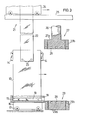
- FIG. 2 shows a pre-press part according to the invention.
- the material to be pressed falls over a filling shaft (12), through the upper housing (11) of the pre-press into a transportable press container, which consists of a box-shaped part (13), automatically working backflow flaps (14) and a removable base plate (15).
- the fibrous material is compressed under the action of the press ram (10), which can be moved via a piston rod (9), and results in the pre-pressed material (20).
- the box-shaped part (13) of preferably rectangular or square cross section is detachably connected to the base plate (15) by means of a holding device (18).
- This holding device can consist, for example, of a tongue and groove guide, as can be found in the simplest form in drawers.
- a blank made of packaging material (19) was inserted for the later lower end face of the bale before the box-shaped part (13) was joined to the base plate (15).
- the pre-pressing usually takes place in such a way that the loose, fibrous material first accumulates in the interior of the box-shaped container (13) and the interior of the upper housing (11) and is compressed in the box-shaped part (13) of the press container by lowering the pre-compression ram (10) becomes.
- the pre-pressing die (10) has been raised again, the filling process is continued and the fibrous material is pre-compressed by alternately filling and lowering the pre-pressing die (10) in the interior of the box-shaped part (13).
- the known backflow flaps (14) serve to prevent the pre-pressed material from swelling out of the cylindrical part (13).
- the position of the backflow flaps (14) can, for example, depend on the position of the press ram (10) can be controlled.
- the press container ie the box-shaped part (13), together with the base plate (15) can be transported away from the area of the pre-press with the aid of the wheels (17).
- An empty container then moves into its place, the base plate (15) of which is again covered with a packaging blank (19).
- the exact position of the press container relative to the press ram (10) can be ensured by suitable locking devices, not shown.
- the press container filled with pre-pressed fiber material (20) can now be transported to the central press on a flat surface. This transport can be facilitated, for example, by a drive (not shown) or by pulling devices.
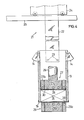
- FIG. 3 shows a filled press container (3) with bottom plate (15) and a combined transfer and conveying device (21).
- the transfer and conveying device which can consist of a gripper device (22), an upper roller carriage (24) and a rail system (25)
- the box-shaped part (13) of the press container becomes horizontal in the work area of the press ram (27) of the central press moved, the holding devices (18) allowing the base plate (15) to be released from the box-shaped part (13) during this horizontal movement.
- Holding devices not shown, ensure that the packaging blank (19) does not change its position during this movement.
- the connection between the gripper devices (22) and the box-shaped part (13) of the press container can take place, for example, using suitable holding devices (23).
- the central press ram (27) is divided in the present case into a core press ram (27a) and an outer press ram (27b), which surrounds the core stamp (27a) in a ring.
- the position of the press ram (27) is brought about by a drive (not shown) via the piston rod (26).
- the bottom pressure plate (29) like the associated press ram, is divided into a core pressure plate (29a) and an outer pressure plate (29b) which surrounds the core pressure plate in a ring.
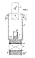
- FIG. 4 shows the actual pressing of the fibrous material with the help of the press ram (27a and b).
- the box-shaped part (13) of the press container is held by the gripper device (22) of the transfer and conveying device (21).
- the use of the packaging blanks (19) and (30) for the end faces of the later bale is necessary for several reasons.
- the method according to the invention permits the packaging of different fibrous goods, that is, also differently colored fiber flakes.
- the packaging blanks (19) and (30) there is a risk f Ahr that fiber material remains in the Schnürnuten (28) of a previous press operation and remains in a subsequent pressing operation of extraneous fibrous material therein.
- the packaging material also has the task of protecting the material pressed into a bale (31) from contamination during later transport and storage.
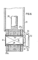
- FIG. 6 shows an automatic wrapping of the now exposed side surfaces of the bale (31) with packaging material using an automatically working wrapping device (5).
- the central press system is shown in cross section in FIG. 6, as in the previous figures, while FIGS. 6a and 6b show the timing of the wrapping process in the supervision.
- FIG. 6 shows again the pressed bale (31), which has packaging blanks (19) and (30) on its end faces.
- the side surfaces of the bale are now covered by a third blank of packaging material (41).
- This third packaging blank (41) comes from a supply roll (32) which is held by arms (33).
- FIGS. 6a and 6b The actual packaging process can be seen in FIGS. 6a and 6b in time. While in FIG. 6a one end of the packaging material web '(35) is held by the swivel device (37) attached to the support arms (36) and the supply roll (32) is swung out far using the swivel arms (33) and the pneumatic actuator (39) the entire device is moved to the compressed bale (31) with the aid of the transport carriage (40) and thereby reaches the end position which was shown in FIG. 6b. By moving the entire wrapping device (5) and by an additional pivoting movement of the support arms (33) about the pivot point (34) and the pivoting of the pivoting device (37), all side surfaces of the bale (31) are enclosed by a film (35).
- a separating and welding device (38) connects the overlapping packaging material webs. Due to the pre-tension with which the wrapping was carried out and the subsequent welding of the separated film web, which bears the identification number (41), a fixation of the position of this web is ensured at the same time.
- the supply roll (32) is then pivoted back by moving the support arms (33) and the transport carriage (40) is moved back. As soon as the automatically operating wrapping device (5) has reached the position according to FIG. 6a again, take over the free end of the packaging material web (35) to the swivel device (37).
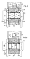
- FIG. 7 shows the hold-down devices fastened to the support frame (44) in the pivoted-in state (42a), while the hold-down devices (42b) of the support frame (43) are already in the pivoted-out working position.
- the pivoting movement of the hold-down device about its pivot point can be carried out by suitable drive devices, which, however, have not been shown in the figure.
- the annular outer punch (27b) and the annular outer pressure plate (29b) can be moved by suitable movement devices, such as e.g. hydraulic control piston. They have suitable incisions which, when the parts (27b) and (29b) are returned to the starting pressing position, make it impossible to damage the pivoted down hold-down devices (42b). After lowering the outer press ram (27b) and lifting the outer pressure plate (29b) accordingly, the hold-down devices (42b) can be retracted because the press parts (27b) and (29b) now project the protruding ends of the packaging material surfaces in their bent positions on the end faces fix the bale.
- suitable movement devices such as e.g. hydraulic control piston. They have suitable incisions which, when the parts (27b) and (29b) are returned to the starting pressing position, make it impossible to damage the pivoted down hold-down devices (42b).
- the hold-down devices (42b) can be retracted because the press parts (27b) and (29b) now project the
- the pressed bale remains on the ground pressure plate (29a, 29b) in the fully packaged state; it can be removed from the press or, for example, can be transferred to another known means of transport for such products via an ejection device, not shown.
- FIG. 9 A variant of the method and the required central press is shown in FIG. 9.
- neither the press ram (27) nor the bottom pressure plate (29) is divided into core and outer parts.
- the packaging areas of the packaging blanks (19) and (30) which protrude beyond the end faces of the bale are not bent onto the end faces but onto the side faces with the aid of hold-down devices (47a, b), (49a, b).
- the levers in the recesses (46) of the press ram (27) t i gen-down device (49a, b) may be their swivel action g u ng conventional means, not shown Antriebsvorrich- t Ungen perform.
- the hold-down device (49a) is drawn in the pivoted-in position, while the hold-down device (49b) is in the working position.
- Hold-down devices (47a, b) are let into the bottom pressure plate (29) and can be moved by means of a pneumatic drive (48). In contrast to the hold-down devices described so far, the hold-down devices (47a, b) only perform an up and down movement.
- the hold-down device (47a) is drawn in the retracted position, the hold-down device (47b) in the extended position.
- the packaging and reinforcement of the bale (31) is advantageously carried out as follows when using a device according to FIG. 9.
- the side surfaces are wrapped with a sheet of packaging material (35).
- the width of this packaging material web was chosen so that it does not exceed the height of the side surfaces of the bale in the pressed state.
- the application of the packaging material web to the side can be done in the manner as already described in FIGS. 6a and b and the associated text.
- the side surfaces are wrapped with packaging material with hold-down devices (47b), (49b) already extended.
- the bale is first reinforced.
- the lower hold-down devices (47b) are then moved into position (47a) while the press ram (27) is raised in position (49b) with the hold-down devices still extended. This procedure allows the hold-down devices to be removed from their position between the individual packaging blanks and the bale is freely available for removal.
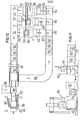
- FIGS. 10 and 11 A further press system according to the invention is shown in FIGS. 10 and 11.
- two pre-presses (1) and (1 ') and a cable laying and pre-pressing device (50) are connected to a central press (55) via routes (51, 52, 5-3 and 54).
- Known cable cutting machines (59, 59 ') are arranged above the pre-presses (1) and (1') and are able to cut the continuous cables (56, 57), which can come from different fiber lines, into staple fibers.
- the staple fibers then fall directly into transportable press containers (60) lined with packaging material.
- the staple fiber flake is pre-pressed directly in the press container.
- the filled press container (60) is moved, for example, via the travel route (51, 52) in the direction of the central press (55).
- a further endless cable (58) which can originate from a further fiber line, is placed in the cable laying and pre-pressing device (50) in a further press container (60) and pre-pressed. If this press container is filled, it can also be moved in the direction of the central press via the routes (51, 54).
- the press container (60) it is expedient to fill the press container (60) with packaging material e.g. to be laid out in a bag shape before filling with fibrous material.
- packaging material e.g. to be laid out in a bag shape before filling with fibrous material.
- the transport of the press container on the routes (51 to 54) can follow again, for example, by a roller conveyor, as indicated in FIG. 11.
- a roller conveyor as indicated in FIG. 11.
- any other device for the horizontal conveying of goods instead of a roller conveyor.
- the press containers (60) can be made weaker, since they only have to withstand the pressure of the pre-press.
- These press containers (60) are removed from the pre-pressed material (70) with the aid of a take-over device (61).
- a take-over device (61) e.g. Takeover device (61) movable on a rail track and corresponding gripping and pulling devices, which were indicated schematically in FIG.
- the pre-pressed material (70) of the press box (60) is moved into the central press with the aid of the take-over device (61), which can be a conventional superstructure press, for example, in which the press chamber can be closed by doors (62, 63).
- the take-over device (61) to introduce the pre-pressed material into the central press (55), in which, after the final pressing, banding can be carried out, for example, with the automatic banding device (45).
- the finished bales (7) can be transported away, for example, via a movable press floor (64) and then further via a driveway (65), which can again be designed as a roller conveyor.
- the empty press container (60) is transported back from the transfer device (61) to the individual pre-presses via the routes (66 to 69).
- the empty press containers (60) can again be equipped with packaging blanks or sets, for example.
- the transfer of the precompressed Guts (70) by the transfer device (61) in the central press can also be performed in this embodiment of the invention, so that is placed on the movable Preßboden (64) prior g epreßte Good (70), in turn, the the rest of the transport to the central press.
- FIGS. 12 and 13 A further embodiment of the invention is shown in FIGS. 12 and 13, in which two depositing and pre-pressing devices (1) for fiber, curl and (50) for cable tape are provided.
- the endless cables (57 and 58) come from the associated fiber lines. While the cable (58) is deposited and pre-pressed directly as a cable band, the endless cable (57) is first cut in the cutting machine (59) and then falls into the pre-press (1).
- the storage and pre-pressing devices (1 and 50) are in turn connected to the central press (71) via routes (51 to 53) and (66 to 68).
- the transportable press containers (72) are filled with fibrous material in the depositing and pre-pressing devices, which is then pressed in these press containers in the central press (71).
- weaker-sized press containers which only have to be designed for the pressure in the pre-presses, if it is ensured that the additional forces occurring in the central press, for example, through supporting walls, that lie on the side surfaces of the press container can be picked up.
Landscapes
- Engineering & Computer Science (AREA)
- Mechanical Engineering (AREA)
- Basic Packing Technique (AREA)
- Press Drives And Press Lines (AREA)
- Auxiliary Devices For And Details Of Packaging Control (AREA)
Applications Claiming Priority (4)
| Application Number | Priority Date | Filing Date | Title |
|---|---|---|---|
| DE19792906229 DE2906229A1 (de) | 1979-02-17 | 1979-02-17 | Verfahren zum verpacken von chemiefasern, wie insbesondere stapelfasern, in ballen und vorrichtung zur durchfuehrung dieses verfahrens |
| DE2906229 | 1979-02-17 | ||
| DE2911958 | 1979-03-27 | ||
| DE2911958A DE2911958C2 (de) | 1979-03-27 | 1979-03-27 | Verfahren zum Verpacken von faserigem Gut in Ballen sowie geeignete Preßanordnung dazu |
Publications (2)
| Publication Number | Publication Date |
|---|---|
| EP0014923A1 true EP0014923A1 (fr) | 1980-09-03 |
| EP0014923B1 EP0014923B1 (fr) | 1987-08-26 |
Family
ID=25777858
Family Applications (1)
| Application Number | Title | Priority Date | Filing Date |
|---|---|---|---|
| EP80100660A Expired EP0014923B1 (fr) | 1979-02-17 | 1980-02-08 | Procédé pour emballer des matériaux fibreux en balles et presse pour sa mise en oeuvre |
Country Status (3)
| Country | Link |
|---|---|
| EP (1) | EP0014923B1 (fr) |
| JP (2) | JPH0613330B2 (fr) |
| DE (1) | DE3072015D1 (fr) |
Cited By (17)
| Publication number | Priority date | Publication date | Assignee | Title |
|---|---|---|---|---|
| EP0029977A1 (fr) * | 1979-11-30 | 1981-06-10 | Hoechst Aktiengesellschaft | Procédé et dispositif pour presser, emballer et cercler en balles des matières fibreuses |
| EP0075162A1 (fr) * | 1981-09-19 | 1983-03-30 | Gerold Fleissner | Presse à balles de matière fibreuse |
| DE3218063A1 (de) * | 1982-05-13 | 1983-11-17 | Gerold Dipl.-Ing. 6073 Egelsbach Fleissner | Verfahren und vorrichtung zum pressen von fasern |
| EP0264757A1 (fr) * | 1986-10-13 | 1988-04-27 | Vepa AG | Procédé et dispositif pour comprimer des matières fibreuses en balles |
| EP0308985A1 (fr) * | 1987-09-25 | 1989-03-29 | FLEISSNER Maschinenfabrik AG | Dispositif pour la mise en balle de matière fibreuse ainsi que presse pour la mise en balle de matière fibreuse |
| US4953344A (en) * | 1986-06-06 | 1990-09-04 | Fiberglas Canada Inc. | Packaging fibre batts |
| EP0405488A1 (fr) * | 1989-06-30 | 1991-01-02 | Hoechst Aktiengesellschaft | Installation pour emballer des fibres courtes dans des petits paquets |
| EP0441753A1 (fr) * | 1990-02-06 | 1991-08-14 | GUALCHIERANI SYSTEM s.a.s. di Sergio Gualchierani & C. | Machine pour comprimer et emballer des balles |
| WO1991017923A1 (fr) * | 1990-05-15 | 1991-11-28 | Autefa Maschinenfabrik Gmbh | Procede et dispositif pour l'emballage de balles compressees |
| US5074101A (en) * | 1989-03-23 | 1991-12-24 | Hoechst Aktiengesellschaft | Process and apparatus for packaging and pressing loose fiber |
| EP0695690A1 (fr) * | 1994-07-13 | 1996-02-07 | FLEISSNER GmbH & Co. KG Maschinenfabrik | Procédé et dispositif pour comprimer et emballer des matières fibreuses en balles |
| DE20017405U1 (de) * | 2000-10-11 | 2002-02-21 | AUTEFA Automation GmbH, 86316 Friedberg | Ballenpressanlage |
| WO2005012098A1 (fr) * | 2003-08-04 | 2005-02-10 | Gualchierani Textile Automation S.P.A. | Dispositif d'emballage installe dans une presse servant a former des balles de materiau textile |
| WO2013025113A1 (fr) * | 2011-08-17 | 2013-02-21 | International Tobacco Machinery Poland Sp. Z O.O. | Procédé et appareil de compression de matériau de tabac |
| EP2746039A3 (fr) * | 2012-12-20 | 2016-06-08 | Krones AG | Système de fabrication et d'emballage et procédé de fabrication et d'emballage de pièces pressées en matériau biologique |
| EP4074501A1 (fr) * | 2021-04-13 | 2022-10-19 | Maschinenfabrik Bermatingen GmbH & Co. KG | Dispositif de surveillance et de commande destiné à la compression des matériaux d'emballage, ainsi que procédé de commande pour le fonctionnement d'un tel dispositif |
| CN116692173A (zh) * | 2023-07-20 | 2023-09-05 | 上海邯祥机电成套设备有限公司 | 一种新型的化纤打包机 |
Citations (10)
| Publication number | Priority date | Publication date | Assignee | Title |
|---|---|---|---|---|
| DE1239656B (de) * | 1964-02-20 | 1967-05-03 | Hoechst Ag | Verfahren und Vorrichtung zum Einlegen von endlosen Faserkabeln |
| AT264294B (de) * | 1964-08-29 | 1968-08-26 | Lindemann Maschfab Gmbh | Vorrichtung zum Dosieren von faserigem Gut, die einer Ballenpresse vorgeschaltet ist |
| DE1586017A1 (de) * | 1967-04-26 | 1970-03-12 | Demag Ag | Vorrichtung zum Pressen und Abpacken von Muell |
| DE1936493A1 (de) * | 1969-07-17 | 1971-02-18 | Continental Moss Gordin Inc | Verfahren und Vorrichtung zum Pressen und Bandagieren von Ballen |
| DE1951113A1 (de) * | 1969-10-10 | 1971-04-22 | Lindemann Maschfab Gmbh | Verfahren zum Pressen und Emballieren von Ballen,insbesondere solchen aus faserigem Gut |
| DE2515158A1 (de) * | 1975-04-08 | 1976-10-21 | Johannes Linke | Ballenpresse eines hubladers |
| DE2523043A1 (de) | 1975-05-24 | 1976-12-02 | Lindemann Maschfab Gmbh | Ballenpresse |
| DE1938602B2 (de) * | 1969-07-30 | 1977-03-24 | Lindemann Maschinenfabrik GmbH, 4000 Düsseldorf | Ballenpresse fuer faseriges gut |
| DE2042004B2 (de) | 1970-08-25 | 1978-08-10 | Lindemann Maschinenfabrik Gmbh, 4000 Duesseldorf | Ballenpresse, insbesondere für faseriges Gut |
| DE2736316A1 (de) | 1977-08-12 | 1979-02-22 | Hoechst Ag | Verfahren und vorrichtung zum pressen und verpacken von fadenkabeln |
Family Cites Families (1)
| Publication number | Priority date | Publication date | Assignee | Title |
|---|---|---|---|---|
| JPS5327892A (en) * | 1976-08-25 | 1978-03-15 | Mitsubishi Heavy Ind Ltd | Compressive packing machine |
-
1980
- 1980-02-08 EP EP80100660A patent/EP0014923B1/fr not_active Expired
- 1980-02-08 DE DE8080100660T patent/DE3072015D1/de not_active Expired
- 1980-02-15 JP JP55016727A patent/JPH0613330B2/ja not_active Expired - Lifetime
-
1991
- 1991-05-13 JP JP3106196A patent/JPH04242513A/ja active Pending
Patent Citations (10)
| Publication number | Priority date | Publication date | Assignee | Title |
|---|---|---|---|---|
| DE1239656B (de) * | 1964-02-20 | 1967-05-03 | Hoechst Ag | Verfahren und Vorrichtung zum Einlegen von endlosen Faserkabeln |
| AT264294B (de) * | 1964-08-29 | 1968-08-26 | Lindemann Maschfab Gmbh | Vorrichtung zum Dosieren von faserigem Gut, die einer Ballenpresse vorgeschaltet ist |
| DE1586017A1 (de) * | 1967-04-26 | 1970-03-12 | Demag Ag | Vorrichtung zum Pressen und Abpacken von Muell |
| DE1936493A1 (de) * | 1969-07-17 | 1971-02-18 | Continental Moss Gordin Inc | Verfahren und Vorrichtung zum Pressen und Bandagieren von Ballen |
| DE1938602B2 (de) * | 1969-07-30 | 1977-03-24 | Lindemann Maschinenfabrik GmbH, 4000 Düsseldorf | Ballenpresse fuer faseriges gut |
| DE1951113A1 (de) * | 1969-10-10 | 1971-04-22 | Lindemann Maschfab Gmbh | Verfahren zum Pressen und Emballieren von Ballen,insbesondere solchen aus faserigem Gut |
| DE2042004B2 (de) | 1970-08-25 | 1978-08-10 | Lindemann Maschinenfabrik Gmbh, 4000 Duesseldorf | Ballenpresse, insbesondere für faseriges Gut |
| DE2515158A1 (de) * | 1975-04-08 | 1976-10-21 | Johannes Linke | Ballenpresse eines hubladers |
| DE2523043A1 (de) | 1975-05-24 | 1976-12-02 | Lindemann Maschfab Gmbh | Ballenpresse |
| DE2736316A1 (de) | 1977-08-12 | 1979-02-22 | Hoechst Ag | Verfahren und vorrichtung zum pressen und verpacken von fadenkabeln |
Cited By (18)
| Publication number | Priority date | Publication date | Assignee | Title |
|---|---|---|---|---|
| EP0029977A1 (fr) * | 1979-11-30 | 1981-06-10 | Hoechst Aktiengesellschaft | Procédé et dispositif pour presser, emballer et cercler en balles des matières fibreuses |
| EP0075162A1 (fr) * | 1981-09-19 | 1983-03-30 | Gerold Fleissner | Presse à balles de matière fibreuse |
| DE3218063A1 (de) * | 1982-05-13 | 1983-11-17 | Gerold Dipl.-Ing. 6073 Egelsbach Fleissner | Verfahren und vorrichtung zum pressen von fasern |
| US4953344A (en) * | 1986-06-06 | 1990-09-04 | Fiberglas Canada Inc. | Packaging fibre batts |
| EP0264757A1 (fr) * | 1986-10-13 | 1988-04-27 | Vepa AG | Procédé et dispositif pour comprimer des matières fibreuses en balles |
| EP0308985A1 (fr) * | 1987-09-25 | 1989-03-29 | FLEISSNER Maschinenfabrik AG | Dispositif pour la mise en balle de matière fibreuse ainsi que presse pour la mise en balle de matière fibreuse |
| US5074101A (en) * | 1989-03-23 | 1991-12-24 | Hoechst Aktiengesellschaft | Process and apparatus for packaging and pressing loose fiber |
| EP0405488A1 (fr) * | 1989-06-30 | 1991-01-02 | Hoechst Aktiengesellschaft | Installation pour emballer des fibres courtes dans des petits paquets |
| EP0441753A1 (fr) * | 1990-02-06 | 1991-08-14 | GUALCHIERANI SYSTEM s.a.s. di Sergio Gualchierani & C. | Machine pour comprimer et emballer des balles |
| WO1991017923A1 (fr) * | 1990-05-15 | 1991-11-28 | Autefa Maschinenfabrik Gmbh | Procede et dispositif pour l'emballage de balles compressees |
| US5317851A (en) * | 1990-05-15 | 1994-06-07 | Autefa Maschinenfabik Gmbh | Process and device for packing pressed bales |
| EP0695690A1 (fr) * | 1994-07-13 | 1996-02-07 | FLEISSNER GmbH & Co. KG Maschinenfabrik | Procédé et dispositif pour comprimer et emballer des matières fibreuses en balles |
| DE20017405U1 (de) * | 2000-10-11 | 2002-02-21 | AUTEFA Automation GmbH, 86316 Friedberg | Ballenpressanlage |
| WO2005012098A1 (fr) * | 2003-08-04 | 2005-02-10 | Gualchierani Textile Automation S.P.A. | Dispositif d'emballage installe dans une presse servant a former des balles de materiau textile |
| WO2013025113A1 (fr) * | 2011-08-17 | 2013-02-21 | International Tobacco Machinery Poland Sp. Z O.O. | Procédé et appareil de compression de matériau de tabac |
| EP2746039A3 (fr) * | 2012-12-20 | 2016-06-08 | Krones AG | Système de fabrication et d'emballage et procédé de fabrication et d'emballage de pièces pressées en matériau biologique |
| EP4074501A1 (fr) * | 2021-04-13 | 2022-10-19 | Maschinenfabrik Bermatingen GmbH & Co. KG | Dispositif de surveillance et de commande destiné à la compression des matériaux d'emballage, ainsi que procédé de commande pour le fonctionnement d'un tel dispositif |
| CN116692173A (zh) * | 2023-07-20 | 2023-09-05 | 上海邯祥机电成套设备有限公司 | 一种新型的化纤打包机 |
Also Published As
| Publication number | Publication date |
|---|---|
| EP0014923B1 (fr) | 1987-08-26 |
| JPH0613330B2 (ja) | 1994-02-23 |
| JPH04242513A (ja) | 1992-08-31 |
| JPS55116524A (en) | 1980-09-08 |
| DE3072015D1 (en) | 1987-10-01 |
Similar Documents
| Publication | Publication Date | Title |
|---|---|---|
| DE2911958C2 (de) | Verfahren zum Verpacken von faserigem Gut in Ballen sowie geeignete Preßanordnung dazu | |
| EP0029977B1 (fr) | Procédé et dispositif pour presser, emballer et cercler en balles des matières fibreuses | |
| EP0014923B1 (fr) | Procédé pour emballer des matériaux fibreux en balles et presse pour sa mise en oeuvre | |
| EP0085399B1 (fr) | Procédé et appareil pour introduire automatiquement des sacs parallélépipédiques | |
| DE69009648T2 (de) | Verfahren zum Verpacken durch Zusammenpressen und Vorrichtung zum Bündeln von zu verpackenden Produkten. | |
| DE2644652A1 (de) | Vorrichtung zum verpacken mehrerer spulen in einen karton oder dergleichen | |
| DE202011051610U1 (de) | Transportvorrichtung für Pressballen | |
| EP0264757B1 (fr) | Procédé et dispositif pour comprimer des matières fibreuses en balles | |
| EP0000881B1 (fr) | Procédé et appareil pour comprimer et emballer des câbles de filature | |
| DE2358546B2 (de) | Vorrichtung zum Verpacken von Körpern aus zusammendrückbarem Material, beispielsweise aus Glasfasern bestehendem Isoliermaterial | |
| EP0681958B1 (fr) | Dispositif pour cercler plus spécialement des marchandises compressibles telles que des feuilles de carton ondulé ou similaires | |
| DE3248711A1 (de) | Verfahren und vorrichtung zum automatischen einlegen von endlosen faserkabeln | |
| DE2553499C3 (de) | Vorrichtung zum Verdichten und Umbinden von ringförmigen Gegenständen | |
| EP1438186A1 (fr) | Procede de compactage de contenants vides en matiere plastique, et presse utilisee a cet effet | |
| EP0388911A1 (fr) | Procédé et dispositif pour emballer et comprimer des fibres | |
| DE4305144C2 (de) | Verfahren und Vorrichtung zum Packen und Bereitstellen von Stapelfasern oder Tow-Fasern | |
| DE2540452A1 (de) | Verfahren und vorrichtung zum umschnueren von in einer kastenpresse hergestellten ballen aus mindestens vorwiegend nichtmetallischem stoff | |
| EP0695690B1 (fr) | Procédé et dispositif pour comprimer et emballer des matières fibreuses en balles | |
| EP3665086B1 (fr) | Dispositif d'emballage et procédé d'emballage | |
| EP2478757B1 (fr) | Presse à empaqueter | |
| DE4210247A1 (de) | Verfahren zum entsorgen und verdichten von abfaellen sowie vorrichtung zur durchfuehrung dieses verfahrens | |
| DE3872180T2 (de) | Anordnung zum verpacken. | |
| DE202015103880U9 (de) | Ballenpresse | |
| EP3842223A1 (fr) | Presse à balles verticale ainsi que son procédé de fonctionnement | |
| DE102020106156A1 (de) | Vertikal-Kasten-Ballenpresse sowie Verfahren zu ihrem Betrieb |
Legal Events
| Date | Code | Title | Description |
|---|---|---|---|
| PUAI | Public reference made under article 153(3) epc to a published international application that has entered the european phase |
Free format text: ORIGINAL CODE: 0009012 |
|
| AK | Designated contracting states |
Designated state(s): BE DE FR GB IT NL |
|
| 17P | Request for examination filed |
Effective date: 19810212 |
|
| GRAA | (expected) grant |
Free format text: ORIGINAL CODE: 0009210 |
|
| AK | Designated contracting states |
Kind code of ref document: B1 Designated state(s): BE DE FR GB IT NL |
|
| REF | Corresponds to: |
Ref document number: 3072015 Country of ref document: DE Date of ref document: 19871001 |
|
| ITF | It: translation for a ep patent filed | ||
| ET | Fr: translation filed | ||
| PLBI | Opposition filed |
Free format text: ORIGINAL CODE: 0009260 |
|
| 26 | Opposition filed |
Opponent name: AUTEFA GMBH Effective date: 19880525 |
|
| NLR1 | Nl: opposition has been filed with the epo |
Opponent name: AUTEFA GMBH |
|
| ITTA | It: last paid annual fee | ||
| PLBN | Opposition rejected |
Free format text: ORIGINAL CODE: 0009273 |
|
| STAA | Information on the status of an ep patent application or granted ep patent |
Free format text: STATUS: OPPOSITION REJECTED |
|
| 27O | Opposition rejected |
Effective date: 19931006 |
|
| NLR2 | Nl: decision of opposition | ||
| PGFP | Annual fee paid to national office [announced via postgrant information from national office to epo] |
Ref country code: FR Payment date: 19990215 Year of fee payment: 20 |
|
| PGFP | Annual fee paid to national office [announced via postgrant information from national office to epo] |
Ref country code: BE Payment date: 19990219 Year of fee payment: 20 |
|
| PGFP | Annual fee paid to national office [announced via postgrant information from national office to epo] |
Ref country code: GB Payment date: 19990222 Year of fee payment: 20 |
|
| PGFP | Annual fee paid to national office [announced via postgrant information from national office to epo] |
Ref country code: NL Payment date: 19990228 Year of fee payment: 20 |
|
| PGFP | Annual fee paid to national office [announced via postgrant information from national office to epo] |
Ref country code: DE Payment date: 19990416 Year of fee payment: 20 |
|
| BE20 | Be: patent expired |
Free format text: 20000208 *VEPA A.G.;*HOECHST A.G. |
|
| PG25 | Lapsed in a contracting state [announced via postgrant information from national office to epo] |
Ref country code: GB Free format text: LAPSE BECAUSE OF EXPIRATION OF PROTECTION Effective date: 20000207 |
|
| PG25 | Lapsed in a contracting state [announced via postgrant information from national office to epo] |
Ref country code: NL Free format text: LAPSE BECAUSE OF EXPIRATION OF PROTECTION Effective date: 20000208 |
|
| REG | Reference to a national code |
Ref country code: GB Ref legal event code: PE20 Effective date: 20000207 |
|
| NLV7 | Nl: ceased due to reaching the maximum lifetime of a patent |
Effective date: 20000208 |
|
| APAH | Appeal reference modified |
Free format text: ORIGINAL CODE: EPIDOSCREFNO |