EP0405488A1 - Installation pour emballer des fibres courtes dans des petits paquets - Google Patents
Installation pour emballer des fibres courtes dans des petits paquets Download PDFInfo
- Publication number
- EP0405488A1 EP0405488A1 EP90112232A EP90112232A EP0405488A1 EP 0405488 A1 EP0405488 A1 EP 0405488A1 EP 90112232 A EP90112232 A EP 90112232A EP 90112232 A EP90112232 A EP 90112232A EP 0405488 A1 EP0405488 A1 EP 0405488A1
- Authority
- EP
- European Patent Office
- Prior art keywords
- chamber
- press
- filling
- packaging system
- bag
- Prior art date
- Legal status (The legal status is an assumption and is not a legal conclusion. Google has not performed a legal analysis and makes no representation as to the accuracy of the status listed.)
- Withdrawn
Links
- 238000004806 packaging method and process Methods 0.000 title claims abstract description 35
- 238000003825 pressing Methods 0.000 claims description 39
- 239000000835 fiber Substances 0.000 claims description 14
- 230000006835 compression Effects 0.000 claims description 6
- 238000007906 compression Methods 0.000 claims description 6
- 239000000463 material Substances 0.000 claims description 6
- 238000004026 adhesive bonding Methods 0.000 claims description 3
- 238000000034 method Methods 0.000 claims description 3
- 238000003466 welding Methods 0.000 claims description 3
- 239000011295 pitch Substances 0.000 claims 1
- 229910000831 Steel Inorganic materials 0.000 description 1
- 239000004744 fabric Substances 0.000 description 1
- 230000005484 gravity Effects 0.000 description 1
- 238000004519 manufacturing process Methods 0.000 description 1
- 238000012858 packaging process Methods 0.000 description 1
- 239000010959 steel Substances 0.000 description 1
- 238000005303 weighing Methods 0.000 description 1
Images






Classifications
-
- B—PERFORMING OPERATIONS; TRANSPORTING
- B65—CONVEYING; PACKING; STORING; HANDLING THIN OR FILAMENTARY MATERIAL
- B65B—MACHINES, APPARATUS OR DEVICES FOR, OR METHODS OF, PACKAGING ARTICLES OR MATERIALS; UNPACKING
- B65B1/00—Packaging fluent solid material, e.g. powders, granular or loose fibrous material, loose masses of small articles, in individual containers or receptacles, e.g. bags, sacks, boxes, cartons, cans, or jars
- B65B1/20—Reducing volume of filled material
- B65B1/24—Reducing volume of filled material by mechanical compression
-
- B—PERFORMING OPERATIONS; TRANSPORTING
- B30—PRESSES
- B30B—PRESSES IN GENERAL
- B30B9/00—Presses specially adapted for particular purposes
- B30B9/30—Presses specially adapted for particular purposes for baling; Compression boxes therefor
- B30B9/3075—Presses specially adapted for particular purposes for baling; Compression boxes therefor with press boxes on a movable carrier, e.g. turntable
Definitions
- the invention relates to a packaging system for short cut fibers in small containers.
- the invention has for its object to provide an automatically operating packaging system for short cut fibers in small containers, which is environmentally friendly and simple in structure and function.
- the packaging system according to the invention is characterized in that a filling chamber can be moved by a transport device between a sack application and filling station and a pressing station, that the filling chamber consists of a tubular body with an open lower end, via which a sack is placed in the sack application station is turned over, and an open upper end, into which a predetermined amount of short cut fibers is filled in the filling station, that a press with a press ram and a counter ram arranged underneath is provided in the press station, which are aligned axially to one another and vertically movable so that to compress the short cut fibers, the press ram can be moved into the stationary filling chamber from above, while the counter ram rests as a counter bearing on the underside of the sack, and both rams can be moved downwards together push the sack contents with the sack out of the filling chamber and that a sack closing device is provided in the pressing station, which closes the upper end of the sack after the pressing process has
- the contents of the sack are compressed in the press station.
- the two punches provided in the pressing station serve both for compacting and for pushing out the contents of the sack from the filling chamber.
- the packaging system is therefore characterized by its structural simplicity and high level of functional reliability. Since it can work fully automatically, the risk of fiber flying is largely avoided.
- a further embodiment of the invention is characterized in that a pressing chamber is arranged in the pressing station below the stationary filling chamber, in which the two punches can be moved so that they insert the contents of the sack with the sack from the filling chamber into the pressing chamber and end there condense.
- the contents of the sack are thus pre-compressed in the filling chamber and finally compressed in the press chamber.
- additional pre-compression can be carried out in the filling station if necessary.
- the press ram is expediently divided into an inner ram and an annular outer ram, which can be moved relative to one another in such a way that the outer ram returns to its starting position or an intermediate position after the final compression, while the inner ram holds down the compressed sack contents to close the sack.
- a discharge device is preferably provided which moves at least the part of the press chamber containing the finished pressed bag from its vertical alignment with the press ram in order to be able to remove the finished pressed bag from the press chamber.
- the small containers are preferably packaged in sizes of 5, 10.15, 20 and 25 kg.
- the filling chamber which expediently has a rectangular cross section, has a length of 400 mm and a width of 100, 200 and 250 mm, for example.
- the height can be 300 to 600 mm.
- the packaging system shown in FIG. 1 has two filling chambers 2, 4, which are offset by 180 ° on two separately movable swivel arms 6, 8 of a transport device 10 designed as a swivel device.
- the pivoting device can be rotated about a vertical axis A, so that the filling chambers 2, 4 can be moved on a circular path between a bag placement station 12, a filling station 14, a waiting station 16 and a pressing station 18.
- the filling chambers 2, 4 are designed as a tubular body of rectangular cross section, the upper and lower ends of which are each open (cf. also FIGS. 2 to 7).
- a ready-made bag made of smooth film, ribbon film, paper, fabric or the like is placed over the lower end of the empty filling chamber. This can be done by hand. However, a semiautomatic or fully automatic device (not shown) for placing the sack is expediently provided, which can be designed similarly to EP 85 399.
- the filling chamber is pivoted into the filling station 14 from the bag placement station 12.
- the filling station 14 is provided with a device 22 (indicated schematically in FIG. 2), through which a certain amount of short cut fibers is filled into the filling chamber from above. The quantity entered can be pre-weighed. Instead, the filling station 14 can be provided with a measuring device 20a (shown schematically in FIG. 1) for determining the weight of the contents of the filling chamber. This measuring device (weighing device) can be designed, for example, as in EP 115 089 or EP 115 070.
- the filling station 14 can be provided with a pressing device 23 which pre-compresses the material with a particularly large volume.
- the pressing device 23 can also be arranged between the bag loading station 12 and the filling station 14 or between the filling station 14 and the waiting station 16 or in the waiting station 16 .
- the pressing station 18 Downstream of the filling station 14 and the waiting station 16 is the pressing station 18, in which the contents of the sack are compressed in two process steps and the sack is then closed, as will be explained in more detail below.
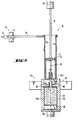
- the pressing station 18 has a pressing device with a pressing die 24, which is actuated by a pneumatic or hydraulic cylinder 26, a counter-punch 28, which is actuated by a pneumatic or hydraulic cylinder 30, and a stationary pressing chamber 32.
- the cylinder 26 of the pressing die 24 is arranged above the position which the filled, surrounded by a bag 20 filling chamber 2 in the pressing station 18, while the pressing chamber 32 and the cylinder 30 of the counter-punch 28 are below this position.
- the arrangement is such that the press ram 24, the counter ram 28, the press chamber 32 and the filling chamber 2 are aligned with one another along a vertical axis B.
- the press ram 24 has a rectangular cross section, which is slightly smaller than that of the filling chamber 2, so that the press ram 24 can move into the filling chamber 2.
- the cross section of the counter punch 28 corresponds to that of the filling chamber 2, so that the counter punch 28 can serve as the bottom of the filling chamber 2.
- the press die 24 and the counter punch 28 are moved down together.
- the sack content 20b with the sack 20 is pushed out of the filling chamber 2 and pushed into the press chamber 32.
- the counter-punch 28 moves from the upper end of the press chamber 32 to its lower end in its lowest position, where it serves as the bottom of the press chamber 32.
- the press ram 24 then ensures that the contents of the bag 20b are finally compressed (FIG. 4).
- the press die 24 is divided into an inner die 24a and an annular outer die 24b, which can be displaced relative to one another by a small pneumatic or hydraulic cylinder 33. While the inner punch 24a holds down the compressed sack contents 20b, after the final compression the outer punch 24b is retracted so far that a bag folding device 35 and a bag closing device 34 extend as far as the inner punch 24a can be driven inside.
- the bag folding device 35 of which FIGS. 5a and 6a show a schematic plan view, has two folding members 36, which are arranged on the end faces of the press chamber 32, and two slides 38, which are arranged on the longitudinal sides of the press chamber 32.
- the press punch 24 with the outer and inner punch will be moved back into its starting position, whereupon the empty filling chamber 2 can be pivoted into the bag placing station 12 .
- the closed sack 20 with the sack content 20b is pushed upward out of the pressing chamber 32 by the counter-punch 28.
- a device 42 for strapping the filled sack with wire, steel or plastic tape, cord or the like can be arranged adjacent to the position that the filling chamber occupies in the pressing station 18.
- the finished container is then removed by hand or by means of a conveyor (eg in the form of a doffing device).
- the press chamber 32 can also be provided with slots and bypasses for strapping material (tape, wire, thread, etc.).
- the pressing station 18 While the finished pressed bag 20 is being pushed out and further processed, the pressing station 18 is inaccessible for feeding a new bag. In this way, the operating cycle (cycle time) is extended unnecessarily.
- the pressing station 18 is provided with a discharge device 50, which creates the possibility that different pressing and packaging processes can take place simultaneously.
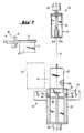
- the pressing chamber 32 is divided into an upper part 32a and a lower part 32b.
- the upper part 32a contains the bag closing device 34 and is arranged in a stationary manner.
- the lower part 32b which contains the finished pressed, closed bag 20, can be moved out of its position aligned with the axis B by the discharge device 50.
- the part 32b of the press chamber together with the counter-punch 28 and its cylinder 30 can be pivoted about an axis perpendicular to the axis B, namely by 90 °.
- the part 32b and the counter-punch 28 perform a translational movement, whereby they are moved from the vertical position shown in FIG. 8 to the horizontal position shown in FIG. 9.
- the discharge device 50 is provided with a telescopic device 52 which acts on the lower part 32b of the press chamber.
- the finished pressed bag 20 can be pushed out from the counter-punch 28 and moved onto a transport and / or stacking device (not shown) will. After the bag 20 has been pushed out, the lower part 32b of the press chamber and the counter-punch 28 are moved back into their position shown in FIG.
- the pressing chamber 32 can be displaced perpendicular to the axis B by two horizontal pneumatic or hydraulic cylinders 62, 64.
- a wall 32c of the press chamber 32 can be moved slightly by the cylinder 62 relative to the rest of the press chamber 32, as indicated by the arrow c.
- the finished pressed bag 20 can leave the press chamber 32 under the action of gravity.
- the entire press chamber 32 can be displaced horizontally with the bag closing device 34.
- the bag closing device 34 instead, however, as in the exemplary embodiment in FIGS. 8, 9, only the lower part of the press chamber could be displaceable, while the upper part containing the bag closing device 34 remains stationary.
- FIG. 12 shows another embodiment of a packaging system which is designed for larger production lines and higher outputs. Components that correspond to components of the previous exemplary embodiment have been provided with the same reference symbols, increased by 100.
- the packaging system shown in FIG. 12 has a larger number of filling chambers 102 which can be moved by a transport device 110 between a larger number of filling stations 114 (114a, 114b ... 114x) and a central pressing station 118.
- the transport device 110 consists of a moving device 110a for empty filling chambers and a moving device 110b for filled filling chambers.
- At least one waiting station 116a, 116b ... 116x is located between the moving device 110a and each filling station 114a, 114b ... 114x (parking space), and there is also at least one waiting station 117a, 117b ... between each filling station and the moving device 110b. 117x (parking space).
- the moving devices 110a, 110b can consist of a rail-bound or rail-less vehicle system or other conveying device.
- the filling stations 114 and the central pressing station 118 are arranged in a row. Instead, they could be disordered.
- the filling stations 114 can at the same time be designed as sack placement stations. Otherwise, the filling stations 114 and the central pressing station 118 have the same structure as in the previous exemplary embodiment.
Landscapes
- Engineering & Computer Science (AREA)
- Mechanical Engineering (AREA)
- Auxiliary Devices For And Details Of Packaging Control (AREA)
Applications Claiming Priority (4)
| Application Number | Priority Date | Filing Date | Title |
|---|---|---|---|
| DE19893921508 DE3921508A1 (de) | 1989-06-30 | 1989-06-30 | Verpackungsanlage fuer kurzschnittfasern in kleingebinden |
| DE3921508 | 1989-06-30 | ||
| DE4002219 | 1990-01-26 | ||
| DE19904002219 DE4002219A1 (de) | 1990-01-26 | 1990-01-26 | Verpackungsanlage fuer kurzschnittfasern in kleingebinden |
Publications (1)
| Publication Number | Publication Date |
|---|---|
| EP0405488A1 true EP0405488A1 (fr) | 1991-01-02 |
Family
ID=25882525
Family Applications (1)
| Application Number | Title | Priority Date | Filing Date |
|---|---|---|---|
| EP90112232A Withdrawn EP0405488A1 (fr) | 1989-06-30 | 1990-06-27 | Installation pour emballer des fibres courtes dans des petits paquets |
Country Status (1)
| Country | Link |
|---|---|
| EP (1) | EP0405488A1 (fr) |
Cited By (2)
| Publication number | Priority date | Publication date | Assignee | Title |
|---|---|---|---|---|
| NL9301103A (nl) * | 1993-06-24 | 1995-01-16 | Theodorus Gijsbertus Maria Van | Werkwijze voor het opslaan en/of transporteren van droge mest alsmede inrichting voor het verdichten en verpakken van droge mest. |
| EP0928555A1 (fr) * | 1997-12-29 | 1999-07-14 | Hans Fankhauser | Dispositif et procédé pour doser un matériau fibreux |
Citations (5)
| Publication number | Priority date | Publication date | Assignee | Title |
|---|---|---|---|---|
| GB940580A (en) * | 1960-09-09 | 1963-10-30 | Saint Eloi Atel | A method and device for packaging bundles of fibre strands |
| GB1117756A (en) * | 1965-12-03 | 1968-06-26 | Kebroyd Mills Ltd | A process and means for preparing textile slivers for dyeing |
| FR2173429A5 (fr) * | 1972-02-24 | 1973-10-05 | Buisson Marcel | |
| EP0014923A1 (fr) * | 1979-02-17 | 1980-09-03 | Vepa AG | Procédé pour emballer des matériaux fibreux en balles et presse pour sa mise en oeuvre |
| WO1986007030A1 (fr) * | 1985-05-31 | 1986-12-04 | Sunds Defibrator Aktiebolag | Procede et appareil pour fabrication de balles de materiau fibreux volumineux |
-
1990
- 1990-06-27 EP EP90112232A patent/EP0405488A1/fr not_active Withdrawn
Patent Citations (5)
| Publication number | Priority date | Publication date | Assignee | Title |
|---|---|---|---|---|
| GB940580A (en) * | 1960-09-09 | 1963-10-30 | Saint Eloi Atel | A method and device for packaging bundles of fibre strands |
| GB1117756A (en) * | 1965-12-03 | 1968-06-26 | Kebroyd Mills Ltd | A process and means for preparing textile slivers for dyeing |
| FR2173429A5 (fr) * | 1972-02-24 | 1973-10-05 | Buisson Marcel | |
| EP0014923A1 (fr) * | 1979-02-17 | 1980-09-03 | Vepa AG | Procédé pour emballer des matériaux fibreux en balles et presse pour sa mise en oeuvre |
| WO1986007030A1 (fr) * | 1985-05-31 | 1986-12-04 | Sunds Defibrator Aktiebolag | Procede et appareil pour fabrication de balles de materiau fibreux volumineux |
Cited By (2)
| Publication number | Priority date | Publication date | Assignee | Title |
|---|---|---|---|---|
| NL9301103A (nl) * | 1993-06-24 | 1995-01-16 | Theodorus Gijsbertus Maria Van | Werkwijze voor het opslaan en/of transporteren van droge mest alsmede inrichting voor het verdichten en verpakken van droge mest. |
| EP0928555A1 (fr) * | 1997-12-29 | 1999-07-14 | Hans Fankhauser | Dispositif et procédé pour doser un matériau fibreux |
Similar Documents
| Publication | Publication Date | Title |
|---|---|---|
| DE19838076B4 (de) | Verfahren und Vorrichtung zum Herstellen von (Groß-)Packungen | |
| DE69009648T2 (de) | Verfahren zum Verpacken durch Zusammenpressen und Vorrichtung zum Bündeln von zu verpackenden Produkten. | |
| DE3123496C2 (fr) | ||
| DE2817094C2 (de) | Vorrichtung zum Zusammenpressen und Verpacken von Polstern aus Isoliermaterial | |
| DE2433687C3 (de) | Verfahren und Vorrichtung zum Entfernen der Bandagen und Umhüllungen von Faserballen | |
| EP0315821A2 (fr) | Dispositif pour amener des coupes à un revolver de pliage d'une machine d'emballage | |
| DE4035352A1 (de) | Vorrichtung zum herstellen von schachteln und zum verpacken von produkten in diese | |
| EP2418151A1 (fr) | Dispositif d'emballage et procédé d'emballage | |
| DE4022120C2 (de) | Vorrichtung zum Füllen von Großpackungen mit einer Anzahl von einzelnen Gegenständen | |
| EP0391118B1 (fr) | Procédé et dispositif pour la fabrication d'emballages pour cigarettes | |
| DE4015642A1 (de) | Verfahren und vorrichtung zum umschlagen einer deckfolie um einen pressballen | |
| DE2906229A1 (de) | Verfahren zum verpacken von chemiefasern, wie insbesondere stapelfasern, in ballen und vorrichtung zur durchfuehrung dieses verfahrens | |
| EP0014923A1 (fr) | Procédé pour emballer des matériaux fibreux en balles et presse pour sa mise en oeuvre | |
| EP0870683B1 (fr) | Procédé et dispositif pour fabriquer (remplir) des sachets de tabac | |
| EP0681958B1 (fr) | Dispositif pour cercler plus spécialement des marchandises compressibles telles que des feuilles de carton ondulé ou similaires | |
| DE3639982A1 (de) | Maschine zur verpackung von gegenstaenden in gruppen | |
| EP0064709A2 (fr) | Dispositif pour emballer des objets dans un emballage collecteur | |
| DE3320459A1 (de) | Verfahren und vorrichtung zum entleeren von tabak-kartons | |
| DE2636320C2 (de) | Vorrichtung zum automatischen Palettieren von Gegenständen, insbesondere Flaschen | |
| EP3665086B1 (fr) | Dispositif d'emballage et procédé d'emballage | |
| DE4002219A1 (de) | Verpackungsanlage fuer kurzschnittfasern in kleingebinden | |
| CH440105A (de) | Doppelbahniger Querpacker | |
| DE2846020C2 (fr) | ||
| DE29517428U1 (de) | Packstück-Umreifungsmaschine, insbesondere für eine sich kreuzende Umreifung von Ballen aus einem zusammenpreßbaren Material, wie vor allem Faservlies oder sonstigem Fasermaterial | |
| DE3921508A1 (de) | Verpackungsanlage fuer kurzschnittfasern in kleingebinden |
Legal Events
| Date | Code | Title | Description |
|---|---|---|---|
| PUAI | Public reference made under article 153(3) epc to a published international application that has entered the european phase |
Free format text: ORIGINAL CODE: 0009012 |
|
| AK | Designated contracting states |
Kind code of ref document: A1 Designated state(s): AT BE CH DE FR GB IT LI NL |
|
| 17P | Request for examination filed |
Effective date: 19901221 |
|
| STAA | Information on the status of an ep patent application or granted ep patent |
Free format text: STATUS: THE APPLICATION HAS BEEN WITHDRAWN |
|
| 18W | Application withdrawn |
Withdrawal date: 19921114 |