EP0014937B1 - Anschlussvorrichtung für Bandkabel - Google Patents
Anschlussvorrichtung für Bandkabel Download PDFInfo
- Publication number
- EP0014937B1 EP0014937B1 EP80100695A EP80100695A EP0014937B1 EP 0014937 B1 EP0014937 B1 EP 0014937B1 EP 80100695 A EP80100695 A EP 80100695A EP 80100695 A EP80100695 A EP 80100695A EP 0014937 B1 EP0014937 B1 EP 0014937B1
- Authority
- EP
- European Patent Office
- Prior art keywords
- base portion
- longitudinal walls
- flat cable
- base
- openings
- Prior art date
- Legal status (The legal status is an assumption and is not a legal conclusion. Google has not performed a legal analysis and makes no representation as to the accuracy of the status listed.)
- Expired
Links
- 239000011810 insulating material Substances 0.000 claims abstract description 9
- 239000004020 conductor Substances 0.000 claims abstract description 8
- 230000000295 complement effect Effects 0.000 description 2
- 230000037431 insertion Effects 0.000 description 2
- 238000003780 insertion Methods 0.000 description 2
- 230000015572 biosynthetic process Effects 0.000 description 1
- 238000009413 insulation Methods 0.000 description 1
- 210000000056 organ Anatomy 0.000 description 1
- 230000035515 penetration Effects 0.000 description 1
- 230000001681 protective effect Effects 0.000 description 1
Images
Classifications
-
- H—ELECTRICITY
- H01—ELECTRIC ELEMENTS
- H01R—ELECTRICALLY-CONDUCTIVE CONNECTIONS; STRUCTURAL ASSOCIATIONS OF A PLURALITY OF MUTUALLY-INSULATED ELECTRICAL CONNECTING ELEMENTS; COUPLING DEVICES; CURRENT COLLECTORS
- H01R12/00—Structural associations of a plurality of mutually-insulated electrical connecting elements, specially adapted for printed circuits, e.g. printed circuit boards [PCB], flat or ribbon cables, or like generally planar structures, e.g. terminal strips, terminal blocks; Coupling devices specially adapted for printed circuits, flat or ribbon cables, or like generally planar structures; Terminals specially adapted for contact with, or insertion into, printed circuits, flat or ribbon cables, or like generally planar structures
- H01R12/70—Coupling devices
- H01R12/77—Coupling devices for flexible printed circuits, flat or ribbon cables or like structures
- H01R12/78—Coupling devices for flexible printed circuits, flat or ribbon cables or like structures connecting to other flexible printed circuits, flat or ribbon cables or like structures
Definitions
- the invention relates to a connecting device for ribbon cables with a base part which extends transversely to the cable run and consists of an insulating material, and an insulating material upper part which can be fastened to the base part.
- a connecting device for ribbon cables with a base part which extends transversely to the cable run and consists of an insulating material, and an insulating material upper part which can be fastened to the base part.
- that. has a U-shaped cross-section with elastically bendable longitudinal walls which at least partially overlap the base part laterally and are provided with latching recesses which cooperate with correspondingly designed counter organs of the base part for fixing the top part to the base part, and with one for guiding the ribbon cable Bridge part which has through openings for the contact elements which can be connected to the individual conductors of the ribbon cable.
- connection device for ribbon cables is known from DE-A1-25 40 550.
- this connection device wire branching
- the bridge part referred to there as the guide body forms a building block which is initially not connected to the other two parts.
- DE-A1-25 41 441 discloses a connecting device for ribbon cables (connectors for flat cables) in which the two essential parts of the device (base member and cover member) can be connected to one another in a first latching position, in which the ribbon cable is inserted a guide slot formed by the two parts can be inserted.
- the height of the guide slot must be dimensioned such that the risk of the ribbon cable getting caught on the contact elements can be avoided.
- a connecting device for ribbon cables in which a first housing half of the device is equipped with the contact elements, and in which a second housing half forms a push-through slot for the ribbon cable on the one hand and, on the other hand, passage openings for those with the Has ribbon cable to be connected sections of the contact elements.
- the guide or push-through slot for the ribbon cable can be dimensioned very narrowly and the cable can be guided / guided exactly without fear of the cable becoming caught on parts of the contact elements protruding into the push-through slot.
- the object of the present invention is therefore to develop a connecting device of the type mentioned at the outset in such a way that the housing parts of the device can be connected to one another before the insertion of a ribbon cable into the apparatus without the sections of the contact elements protruding from one of the housing parts, the insertion of the ribbon cable hinder in the device, or can be damaged yourself.
- this object is achieved in that the bridge part connected integrally with the base part with the formation of a push-through slot for the ribbon cable between the base and bridge part is divided by honeycomb through transverse and longitudinal walls and at least in one section of the upper part, which contains the contact elements when the upper part and the base part are joined together by the upper part longitudinal walls in such a way that the transverse and longitudinal walls of the bridge part complement each other with the upper part longitudinal walls to form the passage openings, and finally the base and upper part are in an upper and a lower latching position to one another can be determined.
- one of the locking positions between the upper part and the base part can advantageously be chosen so that in this position the upper part and the base part are connected, but the push-through slot for the ribbon cable in the base part is free from the sections of the contact element protruding from the upper part, so that the Ribbon cable can be inserted unhindered into the slot.
- the contact element fixed in the upper part is well protected against external influences, since they are enclosed by the longitudinal walls of the upper part and the longitudinal and transverse walls of the bridge part.
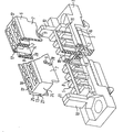
- the figure shows the device with the base part and upper part detached from one another in an oblique view, enlarged and with central regions cut out of the upper part and base part.
- both the base part 1 and the upper part 6 are essentially self-shaped insulating material bodies which are arranged transversely to the course of a ribbon cable, not shown.
- the base part 1 has a support surface 2 for the ribbon cable, into which slots 15 for receiving the tips of fork contacts (not shown) are machined transversely to the ribbon cable run, each contacting a single-cell conductor between them in pairs and thereby piercing the insulating sleeve of the ribbon cable.
- the support surface 2 is provided with ribs 16 which in the direction of Ribbon cables run and each form a guide trough for a ribbon cable - individual conductors by interacting with the ribbed surface structure of the ribbon cable.
- a bridge part 4 is integrally connected such that the bridge part 4 covers the support surface 2 and together with this forms an effective through slot 3 as a guide channel for the ribbon cable in the region of the support surface 2, which is adapted to the ribbon cable.
- the upper part 6 comprises in mutually parallel chambers 17, at right angles pass through the upper part of the cable run, Kontak t teie- elements which form 6 contact springs on the side remote from the cable side of the upper part 18 in the chambers 17th
- the contact springs (not shown) can be contacted with contact knives or contact pins that can be inserted into the chambers 17 on the side 18 of the upper part.
- the contact elements form fork contacts which are arranged in the upper part in such a way that when the upper part 6 and base part 1 are joined they penetrate into the slots 15 of the support surface 2, thereby piercing a support cable 2 lying against the support surface 2 and into their contact slot can pinch one of the individual conductors of the ribbon cable.
- the upper part 6 is essentially U-shaped in cross-section, the U-legs being formed by upper part longitudinal walls 7 which protrude from the upper part in the direction of the base part.
- the bridge part 4 is structured like a honeycomb by transverse and longitudinal walls 19 and is covered by the upper part longitudinal walls 7 at least in a section 20 closer to the upper part 6 when the upper part 6 and base part 1 are joined together.
- the transverse and longitudinal walls 19 of the bridge part 4 complement one another with the upper part longitudinal walls 7 to form passage openings 5 which continue the chambers 17 in the upper part 6 in the base part 1.
- the passage openings 5 are open to the support surface 2, so that the contact elements seated in the chambers 17 of the upper part 6 with sections protruding from the chambers 17 when the upper part 6 and the base part 1 are joined into the passage openings 5 of the base part 1, finally the Fork contacts of the contact elements on the side of the through openings 5 facing the ribbon cable emerge from these and partially protrude into the slots 15 of the contact surface 2 while contacting a single-cell cable.
- connection of the upper part 6 and the base part 1 is effected with the aid of hook-like locking projections 8, which are provided on the transverse walls 19 of the bridge part 4 and, when the upper part 6 and the base part 1 are joined, snap into windows 9 which act as locking recesses and which snap into the longitudinal part of the upper part 7 are incorporated. Since the upper part longitudinal walls 7 have a certain elasticity, the projections 8 can spread the upper part longitudinal walls 7 slightly apart before they snap into the windows 9.
- the contact elements seated in the upper part project with their fork contacts over the upper part longitudinal walls 7 in the direction of the base part 1.
- the upper part 6 can be connected to the base part 1 even before a ribbon cable is inserted into the push-through slot 3.
- a post 10 projecting from the base part 1 in the direction of the upper part 6 from the base part 1 is provided on both sides of the push-through slot 3, the length of which is dimensioned such that it protrudes beyond the bridge part 4 from the base part 1.
- Guide recesses 25 provided on the end faces 24 of the upper part 6 cooperate with latching hooks 11 which act as latching projections and are provided on the mutually facing sides of the posts 10.
- the posts 10 are first slightly spread apart.
- the latching hooks 11 of the posts 10 can reach the guide recesses 25 on the upper part 6 via transverse ribs 27 of the upper part 6.
- the latching hooks 11 rest with their surfaces facing the base part 1 on the side 13 of the ribs 27 facing away from the base part.
- the upper part 6 is held in an upper locking position in the direction of the base part 1 by the locking projections 8 and in the opposite direction by the locking hooks 11.
- the sections of the contact elements projecting from the upper part 6 are still completely in the through openings 5 of the bridge part 4, so that the contact elements do not rain in the through slot 3 for the ribbon cable.
- a ribbon cable to be connected to the connecting device can therefore be inserted unhindered into the slot.
- the upper part is connected in this way to the base part 1 and the portions of the contact elements projecting from the upper part 6 cannot be damaged by careless handling of the connecting device, since they protrude into the through openings 5 in the base part.
- the posts 10 are also offset towards the longitudinal center of the base part to one side, they prevent the upper part 6 from being accidentally connected to the base part 1 by 180 ° can.
- the upper part 6 is pressed against the base part 1 from the upper latching position, the upper part longitudinal walls 7, which are elastic to a certain extent, are spread apart somewhat by the latching projections 8 on the bridge part 4 until further approximation of the upper part 6 on the base part 1 snap the locking projections 8 into the windows 9 on the upper part.
- the fork contacts of the contact elements seated in the upper part 6 have penetrated the insulation of the ribbon cable section seated in the push-through slot 2 and have contacted this conductor as a result of the precise assignment to a single conductor of the cable.
- connection device e.g. a contact device can be connected which contains contact pins or contact knives embedded in a strip-shaped insulating material body. If this device is provided with a protective collar surrounding the contact blades or contact pins, which has a shape corresponding to the post 10, this contact device can also be connected to the connecting device only in a single plug-in position, the posts 10 ensuring the unambiguous assignment of the contact device to the connecting device .
Landscapes
- Coupling Device And Connection With Printed Circuit (AREA)
- Multi-Conductor Connections (AREA)
- Connector Housings Or Holding Contact Members (AREA)
- Details Of Connecting Devices For Male And Female Coupling (AREA)
- Connections By Means Of Piercing Elements, Nuts, Or Screws (AREA)
- Insulated Conductors (AREA)
Description
- Die Erfindung bezieht sich auf eine Anschlußvorrichtung für Bandkabel mit einem quer zum Kabelverlauf sich erstrekkenden, aus einem lsolierstoff bestehenden Basisteil, einem an dem Basisteil befestigbaren Isolierstoff-Oberteil. das .einen U-förmigen Querschnitt mit elastisch ausbiegbaren Längswänden aufweist, die das Basisteil seitlich zumindest teilweise überlappen und mit Rastausnehmungen, die mit entsprechend ausgebildeten Gegenorganen des Basisteiles zur Festlegung des Oberteiles am Basisteil zusammenwirken, versehen sind, und mit einem zur Führung des Bandkabels vorgesehenen Brückenteil, das Durchtrittsöffnungen für die mit den einzelnen Leitern des Bandkabels verbindbaren Kontaktelemente aufweist.
- Ein solche Anschlußvorrichtung für Bandkabel ist aus der DE-A1-25 40 550 bekannt. Bei dieser Anschlußvorrichtung (Ader-Verzweigung) ist es jedoch nicht möglich, die einzelnen Teile der Vorrichtung schon vor dem Einführen des Bandkabels miteinander zu verbinden. Insbesondere bildet das dort als Führkörper bezeichnete Brückenteil einen zunächst nicht mit den beiden anderen Teilen zusammenhängenden Baustein.
- Zwar is aus der DE-A1-25 41 441 eine Anschlußvorrichtung für Bandkabel (Verbinder für Flachkabel ) bekannt, bei der die beiden wesentlichen Teile der Vorrichtung (Basisglied und Abdeckglied) in einer ersten Rastposition miteinander verbunden werden können, in der das Bandkabel'in einen durch die beiden Teile gebildeten Führungsschlitz eingeschoben werden kann. Da bei dieser Vorrichtung jedoch die zum Eindringen in das Bandkabel vorgesehenen Enden der Kontaktelemente in den Führungsschlitz ragen, muß die Höhe des Führungsschlitzes so bemessen werden, daß die Gefahr eines Verhakens des Bandkabels an den Kontaktelementen vermieden werden kann. Dadurch wird aber die Führungseigenschaft des Führungsschlitzes verringert.
- Schließlich ist aus der DE-A1-27 36 244 eine Anschlußvorrichtung für Bandkabel bekannt, bei der eine erste Gehäusehälfte der Vorrichtung mit den Kontaktelementen bestückt ist, und bei der eine zweite Gehäusehälfte einerseits einen Durchsteckschlitz für das Bandkabel bildet und andererseits Durchtrittsöffnungen für die mit dem Bandkabel in Verbindung zu bringenden Abschnitte der Kontaktelemente aufweist. Somit kann der Führungs- bzw. Durchsteckschlitz für das Bandkabel sehr eng bemessen und dadruch das Kabel exakt geführt/werden, ohne daß ein Verhaken des Kabels an in den Durchsteckschlitz ragende Teile der Kontaktelemente befürchtet werden muß.
- Bei all diesen Vorrichtungen stehen jedoch wesentliche Bereiche der Kontaktelemente ungeschützt aus einem der lsoiierstoffteile der Vorrichtung vor.
- Aufgabe vorliegender Erfindung ist es daher, eine Anschlußvorrichtung der eingangs genannten Art so weiterzubilden, daß die Gehäuseteile der Vorrichtung schon vor dem Einführen eines Bandkabels in die Vorrichtung miteinander verbunden werden können, ohne daß dabei aus einem der Gehäuseteile vorstehende Abschnitte der Kontaktelemente das Einführen des Bandkabels in die Vorrichtung behindern, oder selbst beschädigt werden können.
- Erfindungsgemäß ergibt sich die Lösung dieser Aufgabe dadurch, daß das einstückig mit dem Basisteil unter Bildung eines Durchsteckschlitzes für das Bandkabel zwischen Basis- und Brückenteil zusammenhängende Brückenteil durch Quer- und Längswände wabenartig gegliedert und zumindest in einem dem Oberteil, das die Kontaktelemente enthält, nähern abschnitt beim Zusammenfügen von Oberteil und Basisteil von den Oberteil-Längswänden derart umfaßt wird, daß sich die Quer- und Längswände des Brückenteiles mit den Oberteil-Längswänden zur Bildung der Durchtrittsöffnungen ergänzen, und daß schließlich Basis-und Oberteil in einer oberen und einer unteren Rastposition aneinander festlegbar sind.
- Auf diese Weise läßt sich vorteilhaft eine der Rastpositionen zwischen Oberteil und Basisteil so wählen, daß in dieser Position Oberteil und Basisteil zwar verbunden sind, der Durchsteckschlitz für das Bandkabel im Basisteil jedoch von den aus dem Oberteil vorstehenden Abschnitten der Kontaktelement frei ist, so daß das Bandkabel ungehindert in den Durchsteckschlitz eingeschoben werden kann. Die im Oberteil fixierten Kontaktelement sind dabei gegen Einwirkungen von außen gut geschützt, da sie von den Längswänden des Oberteiles und den Längs- und Querwänden des Brückenteiles umschlossen sind.
- Nachfolgend wird ein Ausführungsbeispiel anhand einer Figur noch näher erläutert.
- Die Figur zeigt die Vorrichtung mit voneinander gelöstem Basisteil und Oberteil in Schrägsicht, vergrößert und mit jeweils aus Oberteil und Basisteil herausgeschnittenen .mittleren Bereichen.
- Wie die Figur zeigt, sind sowohl Basisteil 1 als auch Oberteil 6 im wesentlichen ieistenförmige Isolierstoffkörper, die quer zum Verlauf eines nicht dargestellten Bandkabels angeordnet sind. Das Basisteil 1 weist eine Auflagefläche 2 für das Bandkabel auf, in die quer zum Bandkabelverlauf Schlitze 15 zur Aufnahme der Spitzen von Gabelkontakten (nicht dargestellt) eingearbeitet sind, die jeweils paarweise einen Kabeleinzelleiter zwischen sich kontaktieren und hierbei die Isolierstoffhülle des Bandkabels durchstoßen. Außerdem ist die Auflagefläche 2 mit Rippen 16 versehen, die in Richtung des Bandkabels verlaufen und zwischen sich jeweils eine Führungsmulde für einen Bandkabel- Einzelleiter bilden, indem sie mit der rippigen Oberflächenstruktur des Bandkabels zusammenwirken.
- - Mit dem Basisteil 1 ist ein Brückenteil 4 einstückig derart verbunden, daß das Brückenteil 4 die Auflagefläche 2 überdeckt und zusammen mit dieser einen als Führungskanal für das Bandkabel im Bereich der Auflagefläche 2 wirksamen Durchsteckschlitz 3 bildet, der dem Bandkabel angepaßt ist.
- Das Oberteil 6 enthält in zueinander parallelen Kammern 17, die rechtwinklig zum Kabelverlauf das Oberteil durchsetzen, Kontaktteie- mente, die in den Kammern 17 auf der vom Bandkabel abgewandten Seite 18 des Oberteiles 6 Kontaktfedern bilden. Die Kontaktfedem (nicht dargestellt) sind mit in die Kammern 17 auf der Seite 18 des Oberteiles einführbaren Kontaktmessern oder Kontaktstiften kontaktierbar. Auf der dem Bandkabel zugewandten Seite des Oberteiles 6 bilden die Kontaktelemente Gabelkontakte, die im Oberteil so angeordnet sind, daß sie beim Zusammenfügen von Oberteil 6 und Basisteil 1 in die Schlitze 15 der Auflagefläche 2 eindringen, hierbei ein der Auflagefläche 2 anliegendes Bandkabel durchstoßen und in ihrem Kontaktierschlitz einen der Einzelleiter des Bandkabels einklemmen können.
- Das Oberteil 6 ist im Querschnitt im wesentlichen U-förmig ausgebildet, wobei die U-Schenkel durch Oberteil-Längswände 7 gebildet werden, die vom Oberteil in Richtung zum Basisteil abstehen.
- Das Brückenteil 4 ist durch Quer-und Längswände 19 wabenartig gegliedert und wird zumindest in einem dem Oberteil 6 näheren Abschnitt 20 beim Zusammenfügen von Oberteil 6 und Basisteil 1 von den Oberteil-Längswänden 7 umfaßt. Hierbei ergänzen sich die Quer- und Längswände 19 des Brückenteiles 4 mit den Oberteil-Längswänden 7 zur Bildung von Durchtrittsöffnungen 5, die die Kammern 17 im Oberteil 6 im Basisteil 1 fortsetzen. Die Durchtrittsöffnungen 5 sind zur Auflagefläche 2 hin offen, so daß die in den Kammern 17 des Oberteils 6 sitzenden Kontaktelemente mit aus den Kammern 17 vorstehenden Abschnitten beim Zusammenfügen von Oberteil 6 und Basisteil 1 in die Durchtrittsöffnungen 5 des Basisteiles 1 eindringen können, wobei schließlich die Gabelkontakte der Kontaktelemente auf der dem Bandkabel zugewandten Seite der Durchtrittsöffnungen 5 aus diesen heraustreten und unter Kontaktierung eines Kabeleinzelleiters in die Schlitze 15 der Auflagefäche 2 teilweise hineinragen.
- Die Verbindung von Oberteil 6 und Basisteil 1 wird mit Hilfe von hakenartigen Rastvorsprüngen 8 bewirkt, die an den Querwänden 19 des Brückenteiles 4 vorgesehen sind und beim Zusammenfügen von Oberteil 6 und Basisteil 1 in als Rastausnehmungen wirksame Fenster 9 einrasten, die in die Oberteil-Längswände 7 eingearbeitet sind. Da die Oberteil-Längswände 7 eine gewisse Elastizität besitzen, können die Vorsprünge 8 die Oberteil-Längswände 7 vor dem Einrasten in die Fenster 9 geringfügig auseinanderspreizen.
- Die im Oberteil sitzenden Kontaktelemente stehen mit ihren Gabelkontakten über die Oberteil-Längswände 7 in Richtung zum Basisteil 1 vor. Um eine Beschädigung der Kontaktelemente auszuschließen, kann das Oberteil 6 schon vor dem Einschieben eines Bandkabels in den Durchsteckschlitz 3 mit dem Basisteil 1 verbunden werden. Hierzu ist zu beiden Seiten des Durchsteckschlitzes 3 je ein vom Basisteil 1 in Richtung zum Oberteil 6 vom Basisteil 1 abstehender Pfosten 10 vorgesehen, dessen Länge so bemessen ist, daß er über das Brückenteil 4 hinaus von Basisteil 1 absteht. An den Stirnseiten 24 des Oberteiles 6 vorgesehene Führungsausnehmungen 25 arbeiten mit als Rastvorsprünge wirksamen Rasthaken 11 zusammen, die auf den einander zugewandten Seiten der Pfosten 10 vorgesehen sind.
- Wird das Oberteil 6 in dem Raum zwischen den Pfosten 10 bewegt, so werden hierbei zunächst die Pfosten 10 geringfügig auseinandergespreizt. Hierbei können die Rasthaken 11 der Pfosten 10 über Quer-Rippen 27 des Oberteils 6 in die Führungsausnehmungen 25 am Oberteil 6 gelangen. Die Rasthaken 11 liegen dabei mit ihren dem Basisteil 1 zugewandten Flächen auf der vom Basisteil abgewandten Seite 13 der Rippen 27 an. In dieser Position des Oberteiles 6 liegen außerdem die Rastvorsprünge 8 mit vom Basisteil 1 abgewandten Flächen dem Basisteil 1 zugewandten Flächen 14 von Abstützausnehmungen 28 an, die unterhalb der Fenster 9 im Oberteil 6, also auf der dem Basisteil 1 zugewandten Seite der Fenster 9 vorgesehen sind. Auf diese Weise wird das Oberteil 6 in einer oberen Rastposition in Richtung zum Basisteil 1 durch die Rastvorsprünge 8 und in Gegenrichtung durch die Rasthaken 11 festgehalten. In dieser oberen Rastposition befinden sich die aus dem Oberteil 6 vorstehenden Abschnitte der Kontaktelemente noch vollständig in den Durchtrittsöffnungen 5 des Brückenteiles 4, so daß die Kontaktelemente nicht in den Durchsteckerschlitz 3 für das bandkabel regen. Ein mit der Anschlußvorrichtung zu verbindendes Bandkabel kann daher ungehindert in den Durchsteckschlitz eingeschoben werden. Trotzdem ist das Oberteil auf diese Weise mit dem Basisteil 1 verbunden und die aus dem Oberteil 6 vorstehenden Abschnitte der Kontaktelemente können, da sie in die Durchtrittsöffnungen 5 im Basisteil ragen, nicht durch eine unachtsame Handhabung der Anschlußvorrichtung beschädigt werden.
- Da die Pfosten 10 außerdem gegen die Längsmitte des-Basisteiles nach einer Seite hin versetzt vorgesehen sind, verhindern sie, daß das Oberteil 6 versehentlich auch um 180° gedreht mit dem Basisteil 1 verbunden werden kann.
- Wird nach dem Einschieben eines Bandkabels in den Durchsteckschlitz 3 das Oberteil 6 aus der oberen Rastposition gegen das Basisteil 1 gedrückt, so werden hierbei die in einem gewissen Ausmaß elastischen Oberteil-Längswände 7 von den Rastvorsprüngen 8 am Brückenteil 4 etwas auseinandergespreizt bis bie der weiteren Annäherung des Oberteiles 6 an das Basisteil 1 die Rastvorsprünge 8 in die Fenster 9 am Oberteil einrasten. Hierbei haben die Gabelkontakte der im Oberteil 6 sitzenden Kontaktelemente die Isolierung des im Durchsteckschlitz 2 sitzenden Bandkabelabschnittes durchstoßen und infolge der genauen Zuordnung zu einem Einzelleiter des Kabels jeweils diesen Leiter kontaktiert.
- Mit der Anschlußvorrichtung kann nun z.B. eine Kontaktvorrichtung verbunden werden, die in einem leistenförmigen Isolierstoffkörper eingebettete Kontaktstifte oder Kontaktmesser enthält. Versieht man dieser Vorrichtung mit einem die Kontaktmesser oder Kontaktstifte umgebenden Schutzkragen, der eine den Pfosten 10 entsprechende Formgebung aufweist, so kann auch diese Kontaktvorrichtung nur in einer einzigen Steckposition mit der Anschlußvorrichtung verbunden werden, wobei die Pfosten 10 die eindeutige Zuordnung der Kontaktvorrichtung zur Anschlußvorrichtung sicherstellen.
Claims (1)
- Anschlußvorrichtung für Bandkabel mit einem quer zum Kabelverlauf sich erstreckenden, aus einem Isolierstoff bestehenden Basisteil (1), einem an dem Basisteil befestigbaren Isolierstoff-Oberteil (6), das einen U-förmigen Querschnitt mit elastisch ausbiegbaren Längswänden (7) aufweist, die das Basisteil (1) seitlich zumindest teilweise überlappen und mit Rastausnehmungen (9), die mit entsprechend ausgebildeten Gegenorganen (8) des Basisteiles (1) zur Festlegung des Oberteiles (6) am Basisteil (1) zusammenwirken, versehen sind, und mit einem zur Führung des Bandkabels vorgesehenen Brückenteil (4), das Durchtrittsöffnungen (5) für die mit den einzelnen Leitern des Bandkabels verbindbaren Kontaktelemente aufweist, dadurch gekennzeichnet, daß das einstückig mit dem Basisteil (1) unter Bildung eines Durchsteckschlitzes (3) fur das Bandkabel zwischen Basis- und Brückenteil (1, 4) zusammenhängende Brückenteil (4) durch Quer- und Längswände (19) wabenartig gegliedert und zumindest in einem dem Oberteil (6), das die Kontaktelemente enthält, näheren Abschnitt (20) beim Zusammenfügen von Oberteil (6) und Basisteil (1) von den Oberteil-Längswänden (7) derart umfaßt wird, daß sich die Quer- und Längswände (19) des Brückenteiles (4) mit den Oberteil-Längswänden (7) zur Bildung der Durchtrittsöffnungen (5) ergänzen, und daß schließlich Basis- und Oberteil (1, 6) in einer oberen und einer unteren Rastposition aneinander festlegbar sind.
Priority Applications (1)
| Application Number | Priority Date | Filing Date | Title |
|---|---|---|---|
| AT80100695T ATE3681T1 (de) | 1979-02-14 | 1980-02-11 | Anschlussvorrichtung fuer bandkabel. |
Applications Claiming Priority (2)
| Application Number | Priority Date | Filing Date | Title |
|---|---|---|---|
| DE2905693 | 1979-02-14 | ||
| DE2905693A DE2905693C2 (de) | 1979-02-14 | 1979-02-14 | Anschlupvorrichtung für Bandkabel |
Publications (3)
| Publication Number | Publication Date |
|---|---|
| EP0014937A1 EP0014937A1 (de) | 1980-09-03 |
| EP0014937B1 true EP0014937B1 (de) | 1983-06-01 |
| EP0014937B2 EP0014937B2 (de) | 1987-05-13 |
Family
ID=6062937
Family Applications (1)
| Application Number | Title | Priority Date | Filing Date |
|---|---|---|---|
| EP80100695A Expired EP0014937B2 (de) | 1979-02-14 | 1980-02-11 | Anschlussvorrichtung für Bandkabel |
Country Status (5)
| Country | Link |
|---|---|
| EP (1) | EP0014937B2 (de) |
| AT (1) | ATE3681T1 (de) |
| DE (2) | DE2905693C2 (de) |
| DK (1) | DK61380A (de) |
| NO (1) | NO800323L (de) |
Families Citing this family (3)
| Publication number | Priority date | Publication date | Assignee | Title |
|---|---|---|---|---|
| DE3021049C2 (de) * | 1980-06-03 | 1983-05-05 | Siemens AG, 1000 Berlin und 8000 München | Anschlußvorrichtung für Bandkabel |
| DE3334615A1 (de) * | 1983-09-24 | 1985-04-11 | Wilhelm Quante Spezialfabrik für Apparate der Fernmeldetechnik GmbH & Co, 5600 Wuppertal | Stecker fuer elektrische flachkabel |
| GB2198599A (en) * | 1984-06-20 | 1988-06-15 | Trw Connectors | Insulation displacement connector |
Family Cites Families (7)
| Publication number | Priority date | Publication date | Assignee | Title |
|---|---|---|---|---|
| US3245024A (en) * | 1962-03-23 | 1966-04-05 | Evans William Robert | Separable electrical connector for plural conductors |
| GB1505364A (en) * | 1974-09-25 | 1978-03-30 | Thomas & Betts Corp | Electric connector |
| DE2519336C3 (de) * | 1975-04-30 | 1978-08-10 | Siemens Ag, 1000 Berlin Und 8000 Muenchen | AnschluBvorrichtung für Flachbandkabel |
| DE2540550A1 (de) * | 1975-09-11 | 1977-04-07 | Du Pont Nederland | Ader-verzweigung |
| IT1081631B (it) * | 1976-08-13 | 1985-05-21 | Amp Inc | Connettore elettrico |
| US4169647A (en) * | 1978-06-01 | 1979-10-02 | Litton Systems, Inc. | Integral low profile latch for a flat cable connector |
| US4145103A (en) * | 1978-06-01 | 1979-03-20 | Litton Systems, Inc. | Connector with low profile latch |
-
1979
- 1979-02-14 DE DE2905693A patent/DE2905693C2/de not_active Expired
-
1980
- 1980-02-07 NO NO800323A patent/NO800323L/no unknown
- 1980-02-11 AT AT80100695T patent/ATE3681T1/de active
- 1980-02-11 DE DE8080100695T patent/DE3063562D1/de not_active Expired
- 1980-02-11 EP EP80100695A patent/EP0014937B2/de not_active Expired
- 1980-02-13 DK DK61380A patent/DK61380A/da not_active Application Discontinuation
Also Published As
| Publication number | Publication date |
|---|---|
| DK61380A (da) | 1980-08-15 |
| NO800323L (no) | 1980-08-15 |
| EP0014937B2 (de) | 1987-05-13 |
| ATE3681T1 (de) | 1983-06-15 |
| DE2905693A1 (de) | 1980-08-21 |
| DE3063562D1 (en) | 1983-07-07 |
| EP0014937A1 (de) | 1980-09-03 |
| DE2905693C2 (de) | 1982-05-27 |
Similar Documents
| Publication | Publication Date | Title |
|---|---|---|
| DE3850167T2 (de) | Elektrische Verbinderklemme für biegsame gedruckte Leiterplatte. | |
| DE3711675C2 (de) | ||
| DE2941029C2 (de) | ||
| DE69320598T2 (de) | Verbinder | |
| DE3902575C1 (de) | ||
| DE2849419C2 (de) | ||
| DE2735838C2 (de) | Elektrische Anschlußklemme und elektrisches Kabelverbindungsglied | |
| DE3435789A1 (de) | Halterungsblock zum verbinden von verbindungselementen mit der platte eines gedruckten schaltkreises | |
| DE2547166A1 (de) | Elektrische verbinderanordnung | |
| EP0774800B1 (de) | Querverbinder für Reihenklemmen | |
| EP0090317A2 (de) | Vorrichtung zum Anschluss von draht- oder litzenförmigen elektrischen Leitern an Kontaktorgane | |
| EP0736929A1 (de) | Elektrisches Kontaktelement und Kunststoffgehäuse zur Aufnahme des Kontaktelementes | |
| EP0014937B1 (de) | Anschlussvorrichtung für Bandkabel | |
| DE2449950A1 (de) | Schaltereinheit | |
| DE2609291C2 (de) | Schraubenlose Anschlußklemme zur Stromübertragung von elektrischen Leitern | |
| EP0230537A1 (de) | Klemmenleiste sowie Steckeinrichtung mit einer derartigen Klemmenleiste | |
| DE2706988A1 (de) | Schraubenlose anschlussklemme zur stromuebertragung von elektrischen leitern | |
| EP0336166A2 (de) | Schneidklemme zum Anschliessen eines elektrischen Schaltdrahtes | |
| DE1933201A1 (de) | Vorrichtung zum stromuebertragenden Verbinden von elektrischen Leitungen | |
| EP0222039B1 (de) | Leiteranschluss | |
| DE3639793C1 (de) | Kabelmuffe,insbesondere Dropwire-Kabelmuffe fuer Doppelader-Dropwirekabel | |
| EP0060333A1 (de) | Bandkabel-Anschlussvorrichtung | |
| EP0656672B1 (de) | Anschlussleiste zur abisolierfreien Kontaktierung von Adern | |
| DE3122611C2 (de) | Verschlußkappe für elektrische Kontaktsysteme | |
| EP1420481A1 (de) | Anschlusselement |
Legal Events
| Date | Code | Title | Description |
|---|---|---|---|
| PUAI | Public reference made under article 153(3) epc to a published international application that has entered the european phase |
Free format text: ORIGINAL CODE: 0009012 |
|
| AK | Designated contracting states |
Designated state(s): AT BE CH DE FR GB IT NL SE |
|
| 17P | Request for examination filed |
Effective date: 19801015 |
|
| ITF | It: translation for a ep patent filed | ||
| GRAA | (expected) grant |
Free format text: ORIGINAL CODE: 0009210 |
|
| AK | Designated contracting states |
Designated state(s): AT BE CH DE FR GB IT NL SE |
|
| REF | Corresponds to: |
Ref document number: 3681 Country of ref document: AT Date of ref document: 19830615 Kind code of ref document: T |
|
| REF | Corresponds to: |
Ref document number: 3063562 Country of ref document: DE Date of ref document: 19830707 |
|
| ET | Fr: translation filed | ||
| PGFP | Annual fee paid to national office [announced via postgrant information from national office to epo] |
Ref country code: NL Payment date: 19840229 Year of fee payment: 5 |
|
| PLBI | Opposition filed |
Free format text: ORIGINAL CODE: 0009260 |
|
| PGFP | Annual fee paid to national office [announced via postgrant information from national office to epo] |
Ref country code: BE Payment date: 19840331 Year of fee payment: 5 |
|
| 26 | Opposition filed |
Opponent name: AMPHENOL - TUCHEL ELECTRONICS GMBH Effective date: 19840301 |
|
| PGFP | Annual fee paid to national office [announced via postgrant information from national office to epo] |
Ref country code: CH Payment date: 19840524 Year of fee payment: 5 |
|
| PGFP | Annual fee paid to national office [announced via postgrant information from national office to epo] |
Ref country code: SE Payment date: 19841231 Year of fee payment: 6 |
|
| PGFP | Annual fee paid to national office [announced via postgrant information from national office to epo] |
Ref country code: AT Payment date: 19850130 Year of fee payment: 6 |
|
| PG25 | Lapsed in a contracting state [announced via postgrant information from national office to epo] |
Ref country code: CH Effective date: 19850228 |
|
| PG25 | Lapsed in a contracting state [announced via postgrant information from national office to epo] |
Ref country code: NL Effective date: 19850901 |
|
| NLV4 | Nl: lapsed or anulled due to non-payment of the annual fee | ||
| REG | Reference to a national code |
Ref country code: CH Ref legal event code: PL |
|
| PG25 | Lapsed in a contracting state [announced via postgrant information from national office to epo] |
Ref country code: AT Effective date: 19860211 |
|
| PG25 | Lapsed in a contracting state [announced via postgrant information from national office to epo] |
Ref country code: SE Effective date: 19860212 |
|
| PUAH | Patent maintained in amended form |
Free format text: ORIGINAL CODE: 0009272 |
|
| STAA | Information on the status of an ep patent application or granted ep patent |
Free format text: STATUS: PATENT MAINTAINED AS AMENDED |
|
| 27A | Patent maintained in amended form |
Effective date: 19870513 |
|
| AK | Designated contracting states |
Kind code of ref document: B2 Designated state(s): AT BE CH DE FR GB IT NL SE |
|
| BERE | Be: lapsed |
Owner name: SIEMENS A.G. BERLIN UND MUNCHEN Effective date: 19870228 |
|
| EN3 | Fr: translation not filed ** decision concerning opposition | ||
| GBPC | Gb: european patent ceased through non-payment of renewal fee | ||
| PG25 | Lapsed in a contracting state [announced via postgrant information from national office to epo] |
Ref country code: GB Effective date: 19881118 |
|
| PG25 | Lapsed in a contracting state [announced via postgrant information from national office to epo] |
Ref country code: BE Effective date: 19890228 |
|
| PGFP | Annual fee paid to national office [announced via postgrant information from national office to epo] |
Ref country code: FR Payment date: 19890228 Year of fee payment: 10 |
|
| PGFP | Annual fee paid to national office [announced via postgrant information from national office to epo] |
Ref country code: DE Payment date: 19890425 Year of fee payment: 10 |
|
| PG25 | Lapsed in a contracting state [announced via postgrant information from national office to epo] |
Ref country code: DE Effective date: 19901101 |
|
| EUG | Se: european patent has lapsed |
Ref document number: 80100695.8 Effective date: 19861022 |
|
| PG25 | Lapsed in a contracting state [announced via postgrant information from national office to epo] |
Ref country code: FR Free format text: LAPSE BECAUSE OF NON-PAYMENT OF DUE FEES Effective date: 19900228 |
|
| PLAB | Opposition data, opponent's data or that of the opponent's representative modified |
Free format text: ORIGINAL CODE: 0009299OPPO |