EP0014937B1 - Dispositif de connexion pour câbles plats - Google Patents
Dispositif de connexion pour câbles plats Download PDFInfo
- Publication number
- EP0014937B1 EP0014937B1 EP80100695A EP80100695A EP0014937B1 EP 0014937 B1 EP0014937 B1 EP 0014937B1 EP 80100695 A EP80100695 A EP 80100695A EP 80100695 A EP80100695 A EP 80100695A EP 0014937 B1 EP0014937 B1 EP 0014937B1
- Authority
- EP
- European Patent Office
- Prior art keywords
- base portion
- longitudinal walls
- flat cable
- base
- openings
- Prior art date
- Legal status (The legal status is an assumption and is not a legal conclusion. Google has not performed a legal analysis and makes no representation as to the accuracy of the status listed.)
- Expired
Links
- 239000011810 insulating material Substances 0.000 claims abstract description 9
- 239000004020 conductor Substances 0.000 claims abstract description 8
- 230000000295 complement effect Effects 0.000 description 2
- 230000037431 insertion Effects 0.000 description 2
- 238000003780 insertion Methods 0.000 description 2
- 230000015572 biosynthetic process Effects 0.000 description 1
- 238000009413 insulation Methods 0.000 description 1
- 210000000056 organ Anatomy 0.000 description 1
- 230000035515 penetration Effects 0.000 description 1
- 230000001681 protective effect Effects 0.000 description 1
Images
Classifications
-
- H—ELECTRICITY
- H01—ELECTRIC ELEMENTS
- H01R—ELECTRICALLY-CONDUCTIVE CONNECTIONS; STRUCTURAL ASSOCIATIONS OF A PLURALITY OF MUTUALLY-INSULATED ELECTRICAL CONNECTING ELEMENTS; COUPLING DEVICES; CURRENT COLLECTORS
- H01R12/00—Structural associations of a plurality of mutually-insulated electrical connecting elements, specially adapted for printed circuits, e.g. printed circuit boards [PCB], flat or ribbon cables, or like generally planar structures, e.g. terminal strips, terminal blocks; Coupling devices specially adapted for printed circuits, flat or ribbon cables, or like generally planar structures; Terminals specially adapted for contact with, or insertion into, printed circuits, flat or ribbon cables, or like generally planar structures
- H01R12/70—Coupling devices
- H01R12/77—Coupling devices for flexible printed circuits, flat or ribbon cables or like structures
- H01R12/78—Coupling devices for flexible printed circuits, flat or ribbon cables or like structures connecting to other flexible printed circuits, flat or ribbon cables or like structures
Definitions
- the invention relates to a connecting device for ribbon cables with a base part which extends transversely to the cable run and consists of an insulating material, and an insulating material upper part which can be fastened to the base part.
- a connecting device for ribbon cables with a base part which extends transversely to the cable run and consists of an insulating material, and an insulating material upper part which can be fastened to the base part.
- that. has a U-shaped cross-section with elastically bendable longitudinal walls which at least partially overlap the base part laterally and are provided with latching recesses which cooperate with correspondingly designed counter organs of the base part for fixing the top part to the base part, and with one for guiding the ribbon cable Bridge part which has through openings for the contact elements which can be connected to the individual conductors of the ribbon cable.
- connection device for ribbon cables is known from DE-A1-25 40 550.
- this connection device wire branching
- the bridge part referred to there as the guide body forms a building block which is initially not connected to the other two parts.
- DE-A1-25 41 441 discloses a connecting device for ribbon cables (connectors for flat cables) in which the two essential parts of the device (base member and cover member) can be connected to one another in a first latching position, in which the ribbon cable is inserted a guide slot formed by the two parts can be inserted.
- the height of the guide slot must be dimensioned such that the risk of the ribbon cable getting caught on the contact elements can be avoided.
- a connecting device for ribbon cables in which a first housing half of the device is equipped with the contact elements, and in which a second housing half forms a push-through slot for the ribbon cable on the one hand and, on the other hand, passage openings for those with the Has ribbon cable to be connected sections of the contact elements.
- the guide or push-through slot for the ribbon cable can be dimensioned very narrowly and the cable can be guided / guided exactly without fear of the cable becoming caught on parts of the contact elements protruding into the push-through slot.
- the object of the present invention is therefore to develop a connecting device of the type mentioned at the outset in such a way that the housing parts of the device can be connected to one another before the insertion of a ribbon cable into the apparatus without the sections of the contact elements protruding from one of the housing parts, the insertion of the ribbon cable hinder in the device, or can be damaged yourself.
- this object is achieved in that the bridge part connected integrally with the base part with the formation of a push-through slot for the ribbon cable between the base and bridge part is divided by honeycomb through transverse and longitudinal walls and at least in one section of the upper part, which contains the contact elements when the upper part and the base part are joined together by the upper part longitudinal walls in such a way that the transverse and longitudinal walls of the bridge part complement each other with the upper part longitudinal walls to form the passage openings, and finally the base and upper part are in an upper and a lower latching position to one another can be determined.
- one of the locking positions between the upper part and the base part can advantageously be chosen so that in this position the upper part and the base part are connected, but the push-through slot for the ribbon cable in the base part is free from the sections of the contact element protruding from the upper part, so that the Ribbon cable can be inserted unhindered into the slot.
- the contact element fixed in the upper part is well protected against external influences, since they are enclosed by the longitudinal walls of the upper part and the longitudinal and transverse walls of the bridge part.
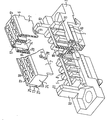
- the figure shows the device with the base part and upper part detached from one another in an oblique view, enlarged and with central regions cut out of the upper part and base part.
- both the base part 1 and the upper part 6 are essentially self-shaped insulating material bodies which are arranged transversely to the course of a ribbon cable, not shown.
- the base part 1 has a support surface 2 for the ribbon cable, into which slots 15 for receiving the tips of fork contacts (not shown) are machined transversely to the ribbon cable run, each contacting a single-cell conductor between them in pairs and thereby piercing the insulating sleeve of the ribbon cable.
- the support surface 2 is provided with ribs 16 which in the direction of Ribbon cables run and each form a guide trough for a ribbon cable - individual conductors by interacting with the ribbed surface structure of the ribbon cable.
- a bridge part 4 is integrally connected such that the bridge part 4 covers the support surface 2 and together with this forms an effective through slot 3 as a guide channel for the ribbon cable in the region of the support surface 2, which is adapted to the ribbon cable.
- the upper part 6 comprises in mutually parallel chambers 17, at right angles pass through the upper part of the cable run, Kontak t teie- elements which form 6 contact springs on the side remote from the cable side of the upper part 18 in the chambers 17th
- the contact springs (not shown) can be contacted with contact knives or contact pins that can be inserted into the chambers 17 on the side 18 of the upper part.
- the contact elements form fork contacts which are arranged in the upper part in such a way that when the upper part 6 and base part 1 are joined they penetrate into the slots 15 of the support surface 2, thereby piercing a support cable 2 lying against the support surface 2 and into their contact slot can pinch one of the individual conductors of the ribbon cable.
- the upper part 6 is essentially U-shaped in cross-section, the U-legs being formed by upper part longitudinal walls 7 which protrude from the upper part in the direction of the base part.
- the bridge part 4 is structured like a honeycomb by transverse and longitudinal walls 19 and is covered by the upper part longitudinal walls 7 at least in a section 20 closer to the upper part 6 when the upper part 6 and base part 1 are joined together.
- the transverse and longitudinal walls 19 of the bridge part 4 complement one another with the upper part longitudinal walls 7 to form passage openings 5 which continue the chambers 17 in the upper part 6 in the base part 1.
- the passage openings 5 are open to the support surface 2, so that the contact elements seated in the chambers 17 of the upper part 6 with sections protruding from the chambers 17 when the upper part 6 and the base part 1 are joined into the passage openings 5 of the base part 1, finally the Fork contacts of the contact elements on the side of the through openings 5 facing the ribbon cable emerge from these and partially protrude into the slots 15 of the contact surface 2 while contacting a single-cell cable.
- connection of the upper part 6 and the base part 1 is effected with the aid of hook-like locking projections 8, which are provided on the transverse walls 19 of the bridge part 4 and, when the upper part 6 and the base part 1 are joined, snap into windows 9 which act as locking recesses and which snap into the longitudinal part of the upper part 7 are incorporated. Since the upper part longitudinal walls 7 have a certain elasticity, the projections 8 can spread the upper part longitudinal walls 7 slightly apart before they snap into the windows 9.
- the contact elements seated in the upper part project with their fork contacts over the upper part longitudinal walls 7 in the direction of the base part 1.
- the upper part 6 can be connected to the base part 1 even before a ribbon cable is inserted into the push-through slot 3.
- a post 10 projecting from the base part 1 in the direction of the upper part 6 from the base part 1 is provided on both sides of the push-through slot 3, the length of which is dimensioned such that it protrudes beyond the bridge part 4 from the base part 1.
- Guide recesses 25 provided on the end faces 24 of the upper part 6 cooperate with latching hooks 11 which act as latching projections and are provided on the mutually facing sides of the posts 10.
- the posts 10 are first slightly spread apart.
- the latching hooks 11 of the posts 10 can reach the guide recesses 25 on the upper part 6 via transverse ribs 27 of the upper part 6.
- the latching hooks 11 rest with their surfaces facing the base part 1 on the side 13 of the ribs 27 facing away from the base part.
- the upper part 6 is held in an upper locking position in the direction of the base part 1 by the locking projections 8 and in the opposite direction by the locking hooks 11.
- the sections of the contact elements projecting from the upper part 6 are still completely in the through openings 5 of the bridge part 4, so that the contact elements do not rain in the through slot 3 for the ribbon cable.
- a ribbon cable to be connected to the connecting device can therefore be inserted unhindered into the slot.
- the upper part is connected in this way to the base part 1 and the portions of the contact elements projecting from the upper part 6 cannot be damaged by careless handling of the connecting device, since they protrude into the through openings 5 in the base part.
- the posts 10 are also offset towards the longitudinal center of the base part to one side, they prevent the upper part 6 from being accidentally connected to the base part 1 by 180 ° can.
- the upper part 6 is pressed against the base part 1 from the upper latching position, the upper part longitudinal walls 7, which are elastic to a certain extent, are spread apart somewhat by the latching projections 8 on the bridge part 4 until further approximation of the upper part 6 on the base part 1 snap the locking projections 8 into the windows 9 on the upper part.
- the fork contacts of the contact elements seated in the upper part 6 have penetrated the insulation of the ribbon cable section seated in the push-through slot 2 and have contacted this conductor as a result of the precise assignment to a single conductor of the cable.
- connection device e.g. a contact device can be connected which contains contact pins or contact knives embedded in a strip-shaped insulating material body. If this device is provided with a protective collar surrounding the contact blades or contact pins, which has a shape corresponding to the post 10, this contact device can also be connected to the connecting device only in a single plug-in position, the posts 10 ensuring the unambiguous assignment of the contact device to the connecting device .
Landscapes
- Coupling Device And Connection With Printed Circuit (AREA)
- Multi-Conductor Connections (AREA)
- Connector Housings Or Holding Contact Members (AREA)
- Details Of Connecting Devices For Male And Female Coupling (AREA)
- Connections By Means Of Piercing Elements, Nuts, Or Screws (AREA)
- Insulated Conductors (AREA)
Claims (1)
- Dispositif de connexion pour câbles plats qui comporte une partie de base (1) qui est constituée par un matériau isolant et s'étend transversalement par rapport à la direction du câble, une partie supérieure (6) en matériau isolant qui peut être fixée sur la partie de base et qui possède une section transversale en forme de U avec des parois longitudinales (7) qui peuvent fléchir élastiquement et qui recouvrent latéralement, au moins partiellement, la partie de base (1) et sont munies d'encoches d'encliquetage (9) qui coopèrent avec des contre- organes (8) de constitution correspondante de la partie de base (1), pour fixer le partie supérieure (6) sur la partie de base (1), ainsi qu'une partie en pont (4) qui est prévue pour le guidage du câble plat et comporte des ouvertures de passage (5) pour les éléments de contact pouvant être couplés aux conducteurs individuels du câble plat, caractérisé par le fait que la partie en pont (4), qui est d'une seule pièce avec la partie de base ( 1 ), en formant une fente de passage (3) pour le câble plat entre la partie de base et la partie en pont (1, 4), est subdivisée en forme de nids d'abeille par des parois transversales et longitudinales (19) et est entourée par les parois longitudinales (7) de la partie supérieure, au moins dans une section (20), qui contient les éléments de contact, plus proche de la partie supérieure (6) lors de l'assemblage de la partie supérieure (6) et de la partie de base (1), de manière que les parois transversales et longitudinales (19) de la partie en pont (4) se complètent avec les parois longitudinales (7) de la partie supérieure, pour former les ouvertures de passage (5), et qu'enfin les parties de base et supérieure (1, 6) puissent être fixées l'une sur l'autre dans une position d'encliquetage supérieure et une position d'encliquetage inférieure.
Priority Applications (1)
| Application Number | Priority Date | Filing Date | Title |
|---|---|---|---|
| AT80100695T ATE3681T1 (de) | 1979-02-14 | 1980-02-11 | Anschlussvorrichtung fuer bandkabel. |
Applications Claiming Priority (2)
| Application Number | Priority Date | Filing Date | Title |
|---|---|---|---|
| DE2905693 | 1979-02-14 | ||
| DE2905693A DE2905693C2 (de) | 1979-02-14 | 1979-02-14 | Anschlupvorrichtung für Bandkabel |
Publications (3)
| Publication Number | Publication Date |
|---|---|
| EP0014937A1 EP0014937A1 (fr) | 1980-09-03 |
| EP0014937B1 true EP0014937B1 (fr) | 1983-06-01 |
| EP0014937B2 EP0014937B2 (fr) | 1987-05-13 |
Family
ID=6062937
Family Applications (1)
| Application Number | Title | Priority Date | Filing Date |
|---|---|---|---|
| EP80100695A Expired EP0014937B2 (fr) | 1979-02-14 | 1980-02-11 | Dispositif de connexion pour câbles plats |
Country Status (5)
| Country | Link |
|---|---|
| EP (1) | EP0014937B2 (fr) |
| AT (1) | ATE3681T1 (fr) |
| DE (2) | DE2905693C2 (fr) |
| DK (1) | DK61380A (fr) |
| NO (1) | NO800323L (fr) |
Families Citing this family (3)
| Publication number | Priority date | Publication date | Assignee | Title |
|---|---|---|---|---|
| DE3021049C2 (de) * | 1980-06-03 | 1983-05-05 | Siemens AG, 1000 Berlin und 8000 München | Anschlußvorrichtung für Bandkabel |
| DE3334615A1 (de) * | 1983-09-24 | 1985-04-11 | Wilhelm Quante Spezialfabrik für Apparate der Fernmeldetechnik GmbH & Co, 5600 Wuppertal | Stecker fuer elektrische flachkabel |
| GB2198599A (en) * | 1984-06-20 | 1988-06-15 | Trw Connectors | Insulation displacement connector |
Family Cites Families (7)
| Publication number | Priority date | Publication date | Assignee | Title |
|---|---|---|---|---|
| US3245024A (en) * | 1962-03-23 | 1966-04-05 | Evans William Robert | Separable electrical connector for plural conductors |
| GB1505364A (en) * | 1974-09-25 | 1978-03-30 | Thomas & Betts Corp | Electric connector |
| DE2519336C3 (de) * | 1975-04-30 | 1978-08-10 | Siemens Ag, 1000 Berlin Und 8000 Muenchen | AnschluBvorrichtung für Flachbandkabel |
| DE2540550A1 (de) * | 1975-09-11 | 1977-04-07 | Du Pont Nederland | Ader-verzweigung |
| IT1081631B (it) * | 1976-08-13 | 1985-05-21 | Amp Inc | Connettore elettrico |
| US4169647A (en) * | 1978-06-01 | 1979-10-02 | Litton Systems, Inc. | Integral low profile latch for a flat cable connector |
| US4145103A (en) * | 1978-06-01 | 1979-03-20 | Litton Systems, Inc. | Connector with low profile latch |
-
1979
- 1979-02-14 DE DE2905693A patent/DE2905693C2/de not_active Expired
-
1980
- 1980-02-07 NO NO800323A patent/NO800323L/no unknown
- 1980-02-11 AT AT80100695T patent/ATE3681T1/de active
- 1980-02-11 DE DE8080100695T patent/DE3063562D1/de not_active Expired
- 1980-02-11 EP EP80100695A patent/EP0014937B2/fr not_active Expired
- 1980-02-13 DK DK61380A patent/DK61380A/da not_active Application Discontinuation
Also Published As
| Publication number | Publication date |
|---|---|
| DK61380A (da) | 1980-08-15 |
| NO800323L (no) | 1980-08-15 |
| EP0014937B2 (fr) | 1987-05-13 |
| ATE3681T1 (de) | 1983-06-15 |
| DE2905693A1 (de) | 1980-08-21 |
| DE3063562D1 (en) | 1983-07-07 |
| EP0014937A1 (fr) | 1980-09-03 |
| DE2905693C2 (de) | 1982-05-27 |
Similar Documents
| Publication | Publication Date | Title |
|---|---|---|
| DE3850167T2 (de) | Elektrische Verbinderklemme für biegsame gedruckte Leiterplatte. | |
| DE3711675C2 (fr) | ||
| DE2941029C2 (fr) | ||
| DE69320598T2 (de) | Verbinder | |
| DE3902575C1 (fr) | ||
| DE2849419C2 (fr) | ||
| DE2735838C2 (de) | Elektrische Anschlußklemme und elektrisches Kabelverbindungsglied | |
| DE3435789A1 (de) | Halterungsblock zum verbinden von verbindungselementen mit der platte eines gedruckten schaltkreises | |
| DE2547166A1 (de) | Elektrische verbinderanordnung | |
| EP0774800B1 (fr) | Connecteur transversal pour blocs de jonction | |
| EP0090317A2 (fr) | Dispositif pour connecter des conducteurs électriques en forme de fil ou de brin | |
| EP0736929A1 (fr) | Elément de contact électrique et boîtier en plastique pour la réception cet élément | |
| EP0014937B1 (fr) | Dispositif de connexion pour câbles plats | |
| DE2449950A1 (de) | Schaltereinheit | |
| DE2609291C2 (de) | Schraubenlose Anschlußklemme zur Stromübertragung von elektrischen Leitern | |
| EP0230537A1 (fr) | Barrette à bornes ainsi qu'un dispositif de connexion avec une de ces barrettes à bornes | |
| DE2706988A1 (de) | Schraubenlose anschlussklemme zur stromuebertragung von elektrischen leitern | |
| EP0336166A2 (fr) | Contact tranchant pour la connexion d'un fil électrique | |
| DE1933201A1 (de) | Vorrichtung zum stromuebertragenden Verbinden von elektrischen Leitungen | |
| EP0222039B1 (fr) | Raccordement de conducteurs | |
| DE3639793C1 (de) | Kabelmuffe,insbesondere Dropwire-Kabelmuffe fuer Doppelader-Dropwirekabel | |
| EP0060333A1 (fr) | Dispositif de connexion pour câbles plats | |
| EP0656672B1 (fr) | Réglette de raccordement pour raccorder des fils sans dénudage | |
| DE3122611C2 (de) | Verschlußkappe für elektrische Kontaktsysteme | |
| EP1420481A1 (fr) | Elément de raccordement |
Legal Events
| Date | Code | Title | Description |
|---|---|---|---|
| PUAI | Public reference made under article 153(3) epc to a published international application that has entered the european phase |
Free format text: ORIGINAL CODE: 0009012 |
|
| AK | Designated contracting states |
Designated state(s): AT BE CH DE FR GB IT NL SE |
|
| 17P | Request for examination filed |
Effective date: 19801015 |
|
| ITF | It: translation for a ep patent filed | ||
| GRAA | (expected) grant |
Free format text: ORIGINAL CODE: 0009210 |
|
| AK | Designated contracting states |
Designated state(s): AT BE CH DE FR GB IT NL SE |
|
| REF | Corresponds to: |
Ref document number: 3681 Country of ref document: AT Date of ref document: 19830615 Kind code of ref document: T |
|
| REF | Corresponds to: |
Ref document number: 3063562 Country of ref document: DE Date of ref document: 19830707 |
|
| ET | Fr: translation filed | ||
| PGFP | Annual fee paid to national office [announced via postgrant information from national office to epo] |
Ref country code: NL Payment date: 19840229 Year of fee payment: 5 |
|
| PLBI | Opposition filed |
Free format text: ORIGINAL CODE: 0009260 |
|
| PGFP | Annual fee paid to national office [announced via postgrant information from national office to epo] |
Ref country code: BE Payment date: 19840331 Year of fee payment: 5 |
|
| 26 | Opposition filed |
Opponent name: AMPHENOL - TUCHEL ELECTRONICS GMBH Effective date: 19840301 |
|
| PGFP | Annual fee paid to national office [announced via postgrant information from national office to epo] |
Ref country code: CH Payment date: 19840524 Year of fee payment: 5 |
|
| PGFP | Annual fee paid to national office [announced via postgrant information from national office to epo] |
Ref country code: SE Payment date: 19841231 Year of fee payment: 6 |
|
| PGFP | Annual fee paid to national office [announced via postgrant information from national office to epo] |
Ref country code: AT Payment date: 19850130 Year of fee payment: 6 |
|
| PG25 | Lapsed in a contracting state [announced via postgrant information from national office to epo] |
Ref country code: CH Effective date: 19850228 |
|
| PG25 | Lapsed in a contracting state [announced via postgrant information from national office to epo] |
Ref country code: NL Effective date: 19850901 |
|
| NLV4 | Nl: lapsed or anulled due to non-payment of the annual fee | ||
| REG | Reference to a national code |
Ref country code: CH Ref legal event code: PL |
|
| PG25 | Lapsed in a contracting state [announced via postgrant information from national office to epo] |
Ref country code: AT Effective date: 19860211 |
|
| PG25 | Lapsed in a contracting state [announced via postgrant information from national office to epo] |
Ref country code: SE Effective date: 19860212 |
|
| PUAH | Patent maintained in amended form |
Free format text: ORIGINAL CODE: 0009272 |
|
| STAA | Information on the status of an ep patent application or granted ep patent |
Free format text: STATUS: PATENT MAINTAINED AS AMENDED |
|
| 27A | Patent maintained in amended form |
Effective date: 19870513 |
|
| AK | Designated contracting states |
Kind code of ref document: B2 Designated state(s): AT BE CH DE FR GB IT NL SE |
|
| BERE | Be: lapsed |
Owner name: SIEMENS A.G. BERLIN UND MUNCHEN Effective date: 19870228 |
|
| EN3 | Fr: translation not filed ** decision concerning opposition | ||
| GBPC | Gb: european patent ceased through non-payment of renewal fee | ||
| PG25 | Lapsed in a contracting state [announced via postgrant information from national office to epo] |
Ref country code: GB Effective date: 19881118 |
|
| PG25 | Lapsed in a contracting state [announced via postgrant information from national office to epo] |
Ref country code: BE Effective date: 19890228 |
|
| PGFP | Annual fee paid to national office [announced via postgrant information from national office to epo] |
Ref country code: FR Payment date: 19890228 Year of fee payment: 10 |
|
| PGFP | Annual fee paid to national office [announced via postgrant information from national office to epo] |
Ref country code: DE Payment date: 19890425 Year of fee payment: 10 |
|
| PG25 | Lapsed in a contracting state [announced via postgrant information from national office to epo] |
Ref country code: DE Effective date: 19901101 |
|
| EUG | Se: european patent has lapsed |
Ref document number: 80100695.8 Effective date: 19861022 |
|
| PG25 | Lapsed in a contracting state [announced via postgrant information from national office to epo] |
Ref country code: FR Free format text: LAPSE BECAUSE OF NON-PAYMENT OF DUE FEES Effective date: 19900228 |
|
| PLAB | Opposition data, opponent's data or that of the opponent's representative modified |
Free format text: ORIGINAL CODE: 0009299OPPO |