EP0015510B1 - Dispositif pour réduire le flux de chaleur local à travers un tube d'échangeur de chaleur - Google Patents
Dispositif pour réduire le flux de chaleur local à travers un tube d'échangeur de chaleur Download PDFInfo
- Publication number
- EP0015510B1 EP0015510B1 EP80101000A EP80101000A EP0015510B1 EP 0015510 B1 EP0015510 B1 EP 0015510B1 EP 80101000 A EP80101000 A EP 80101000A EP 80101000 A EP80101000 A EP 80101000A EP 0015510 B1 EP0015510 B1 EP 0015510B1
- Authority
- EP
- European Patent Office
- Prior art keywords
- tube
- insulating
- tubes
- support means
- insulating sleeve
- Prior art date
- Legal status (The legal status is an assumption and is not a legal conclusion. Google has not performed a legal analysis and makes no representation as to the accuracy of the status listed.)
- Expired
Links
- 230000004907 flux Effects 0.000 title claims description 6
- 239000012530 fluid Substances 0.000 claims description 19
- XLYOFNOQVPJJNP-UHFFFAOYSA-N water Substances O XLYOFNOQVPJJNP-UHFFFAOYSA-N 0.000 claims description 16
- 238000010438 heat treatment Methods 0.000 claims description 4
- 230000004888 barrier function Effects 0.000 claims description 3
- 238000005260 corrosion Methods 0.000 claims description 3
- 230000007797 corrosion Effects 0.000 claims description 3
- 239000007788 liquid Substances 0.000 claims description 3
- 239000007787 solid Substances 0.000 description 9
- 230000008020 evaporation Effects 0.000 description 6
- 238000001704 evaporation Methods 0.000 description 6
- 239000002184 metal Substances 0.000 description 3
- 238000000034 method Methods 0.000 description 3
- 238000009825 accumulation Methods 0.000 description 2
- 230000008021 deposition Effects 0.000 description 2
- 239000007791 liquid phase Substances 0.000 description 2
- 238000001556 precipitation Methods 0.000 description 2
- 230000001133 acceleration Effects 0.000 description 1
- 238000009835 boiling Methods 0.000 description 1
- 230000003467 diminishing effect Effects 0.000 description 1
- 229910001055 inconels 600 Inorganic materials 0.000 description 1
- 238000009413 insulation Methods 0.000 description 1
- 239000000203 mixture Substances 0.000 description 1
- 230000003068 static effect Effects 0.000 description 1
Images


Classifications
-
- F—MECHANICAL ENGINEERING; LIGHTING; HEATING; WEAPONS; BLASTING
- F28—HEAT EXCHANGE IN GENERAL
- F28F—DETAILS OF HEAT-EXCHANGE AND HEAT-TRANSFER APPARATUS, OF GENERAL APPLICATION
- F28F19/00—Preventing the formation of deposits or corrosion, e.g. by using filters or scrapers
- F28F19/002—Preventing the formation of deposits or corrosion, e.g. by using filters or scrapers by using inserts or attachments
-
- F—MECHANICAL ENGINEERING; LIGHTING; HEATING; WEAPONS; BLASTING
- F22—STEAM GENERATION
- F22B—METHODS OF STEAM GENERATION; STEAM BOILERS
- F22B1/00—Methods of steam generation characterised by form of heating method
- F22B1/02—Methods of steam generation characterised by form of heating method by exploitation of the heat content of hot heat carriers
- F22B1/023—Methods of steam generation characterised by form of heating method by exploitation of the heat content of hot heat carriers with heating tubes for nuclear reactors, as long as they are not classified according to a specified heating fluid, in another group
-
- F—MECHANICAL ENGINEERING; LIGHTING; HEATING; WEAPONS; BLASTING
- F22—STEAM GENERATION
- F22B—METHODS OF STEAM GENERATION; STEAM BOILERS
- F22B37/00—Component parts or details of steam boilers
- F22B37/02—Component parts or details of steam boilers applicable to more than one kind or type of steam boiler
- F22B37/10—Water tubes; Accessories therefor
- F22B37/18—Inserts, e.g. for receiving deposits from water
-
- F—MECHANICAL ENGINEERING; LIGHTING; HEATING; WEAPONS; BLASTING
- F22—STEAM GENERATION
- F22B—METHODS OF STEAM GENERATION; STEAM BOILERS
- F22B37/00—Component parts or details of steam boilers
- F22B37/02—Component parts or details of steam boilers applicable to more than one kind or type of steam boiler
- F22B37/10—Water tubes; Accessories therefor
- F22B37/20—Supporting arrangements, e.g. for securing water-tube sets
- F22B37/205—Supporting and spacing arrangements for tubes of a tube bundle
Definitions
- tube supports are used to minimize tube vibration induced by the fluid flowing on the shell side of the exchanger.
- Three tube supports may be drilled plates, machined plates with various clearances around the tube or lattice supports built from metal strips or bars.
- crevices there exists areas of tight clearance between the tube and support which can be referred to as crevices.
- the shell side fluid which is the fluid being heated, in flowing through the crevices is partially or wholly evaporated by the heat transferred from the tube side fluid to the shell side fluid.
- a sleeve is positioned and secured inside a tube of a nuclear steam generator at a location adjacent to a tube support member.
- the sleeve is of small enough dimension that a gap exists between the sleeve and the inner wall of the tube, which gap is filled with stagnant water, forming an insulation barrier. This reduces the heat flux in the crevice region between the tube and tube support member, thereby diminishing the amount of liquid evaporated and thus minimizing the amount of solids deposited in the crevice.
- the flow inlet end of the sleeve is rolled into the tube in order to hold it in position, and drain holes are provided so that water is not trapped therein when the unit is not operating.
- numeral 10 denotes a nuclear steam generator in which heating fluid, being water at high temperature, flows from inlet manifold 12, through tubes 14, and out of the outlet manifold 16. All of the tubes 14 are secured at their bottom ends to a tube sheet 18.
- the inlet fluid generally being water below saturation temperature, enters the shell 20 through the inlet 22, mixes with the recirculatory fluid while flowing downwardly through the annular space between the shell 20 and shroud 28, thence upwardly through the tube bundle 14, absorbing heat in doing so, forming a mixture of steam and water.
- the separators 24 at the top of the vessel separate the water from the steam.
- the steam leaves the unit through outlet 26, and the water flows down the annular space for mixing with the water entering the shell 20 through inlet 22.
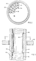
- Tube supports 30 Positioned at a number of vertical locations throughout the vessel are a series of tube supports 30. These supports, which are for the purpose of preventing tube vibration induced by the fluid flowing on the shell side of the heat exchanger may be drilled plates 32 as shown in Figure 2, having oversized holes 34 therein, so that they not only keep the tubes in place and prevent vibration, but also permit flow therethrough. If desired, additional flow holes 36 are formed in the plate 32 to permit flow of the heated fluid therethrough.
- the tube supports could also be in other forms, for example a grid made up of strips or bars of metal, such as shown in U.S. Patent 3,941,188, if desired.
- crevices there exist areas of tight clearance between the tube and support which are hereafter referred to as "crevices".
- the shell side fluid which flows through the crevices is partially or wholly evaporated by the heat transferred from the tube side to the shell side fluid.
- concentration of dissolved solids in the liquid phase may reach the saturation limit so that further evaporation of water will result in precipitation of solids on the tube and plate surfaces.
- the crevice formed by a tube and its support is especially vulnerable to high solids deposition due to partial or total evaporation of the water as it flows through the crevice.
- the solids accumulation in the crevice is undesirable, as it can lead to complete blockage of flow through the crevice which increases shell side pressure drop and may induce localized tube corrosion or other phenomena which could reduce the service life of the tube.
- a metal insulating sleeve 40 ( Figures 3 and 4) is positioned inside of each tube at a location adjacent to the support, to minimize the heat flux or heat transfer to the fluid flowing through the crevice between the tube and support.
- the outer diameter of sleeve 40 is somewhat smaller than the inner diameter of the tube 14, so that a layer of stagnant water is trapped in the annular space therebetween. The stagnant water forms an effective insulating barrier, greatly reducing heat transfer.
- the insulating sleeve 40 can be secured to the tube 14 in any suitable manner.
- the preferred method would be to expand the lower end of the sleeve into tight engagement with the tube, as shown at 42. This could be done by using pressurized hydraulic or pneumatic fluid inside a flexible bag that can be inserted in the tube through the opened bottom end. If desired, the top end of the insulating sleeve can also be expanded. Drain holes 44 are located near the bottom of the insulating sleeve 40, to allow the annular space to drain when the unit is not operating. Bleed holes 48 are located at the top to prevent air from becoming trapped behind the sleeves.
- a flow distribution plate 46 ( Figures 1 and 5) is located above the tube sheet 18. This plate is for the purpose of distributing the flow more equally across the entire cross-section of the shell.
- a distribution plate it may be desirable to minimize the heat flux in the entire space between the tube sheet and the distribution plate, in addition to the crevices between the distribution plate 46 and the tubes 18.
- the insulating sleeves 50 extend from the tube sheet 18 to a point above the distribution plate 46 in this arrangement.
- this arrangement minimizes boiling in the entire space below the distribution plate 46, in addition to the area directly adjacent to the distribution plate.
Landscapes
- Engineering & Computer Science (AREA)
- Physics & Mathematics (AREA)
- Thermal Sciences (AREA)
- Mechanical Engineering (AREA)
- General Engineering & Computer Science (AREA)
- Life Sciences & Earth Sciences (AREA)
- Sustainable Development (AREA)
- Sustainable Energy (AREA)
- Heat-Exchange Devices With Radiators And Conduit Assemblies (AREA)
Claims (3)
Applications Claiming Priority (2)
| Application Number | Priority Date | Filing Date | Title |
|---|---|---|---|
| US17649 | 1979-03-05 | ||
| US06/017,649 US4191246A (en) | 1979-03-05 | 1979-03-05 | Device to reduce local heat flux through a heat exchanger tube |
Publications (2)
| Publication Number | Publication Date |
|---|---|
| EP0015510A1 EP0015510A1 (fr) | 1980-09-17 |
| EP0015510B1 true EP0015510B1 (fr) | 1982-06-30 |
Family
ID=21783786
Family Applications (1)
| Application Number | Title | Priority Date | Filing Date |
|---|---|---|---|
| EP80101000A Expired EP0015510B1 (fr) | 1979-03-05 | 1980-02-28 | Dispositif pour réduire le flux de chaleur local à travers un tube d'échangeur de chaleur |
Country Status (4)
| Country | Link |
|---|---|
| US (1) | US4191246A (fr) |
| EP (1) | EP0015510B1 (fr) |
| DE (1) | DE3060607D1 (fr) |
| ES (1) | ES8101264A1 (fr) |
Families Citing this family (36)
| Publication number | Priority date | Publication date | Assignee | Title |
|---|---|---|---|---|
| DE3049409C2 (de) * | 1980-12-23 | 1983-12-01 | Borsig Gmbh, 1000 Berlin | Einrichtung zur Dampferzeugung in Ammoniak-Synthese-Anlagen |
| US4423703A (en) | 1981-03-09 | 1984-01-03 | Electric Power Research Institute, Inc. | Steam generator or like apparatus including self-cleaning heating element support arrangement |
| US4436146A (en) | 1981-05-20 | 1984-03-13 | Union Carbide Corporation | Shell and tube heat exchanger |
| FR2506498B1 (fr) * | 1981-05-22 | 1986-03-07 | Commissariat Energie Atomique | Reacteur nucleaire a neutrons rapides muni de dispositifs d'evacuation de la puissance residuelle |
| USH119H (en) | 1983-07-15 | 1986-09-02 | The United States Of America As Represented By The United States Department Of Energy | Passive emergency core cooling system for a liquid metal fast |
| US4579087A (en) * | 1983-12-21 | 1986-04-01 | Westinghouse Electric Corp. | Corrosion resistant steam generator and method of making same |
| US4590991A (en) * | 1984-01-09 | 1986-05-27 | Westinghouse Electric Corp. | Flexible stabilizer for degraded heat exchanger tubing |
| US4576228A (en) * | 1984-02-03 | 1986-03-18 | The United States Of America As Represented By The United States Department Of Energy | Minimum wear tube support hole design |
| GB2156463A (en) * | 1984-03-22 | 1985-10-09 | Nat Nuclear Corp Ltd | Pipe junction-internal insulation |
| FR2565322B1 (fr) * | 1984-05-29 | 1986-08-01 | Commissariat Energie Atomique | Dispositif d'injection d'un liquide dans un tube et generateur de vapeur comportant ce dispositif |
| FR2592147B1 (fr) * | 1985-12-23 | 1988-03-18 | Stein Industrie | Dispositif de controle de debit dans un tube d'echangeur de chaleur. |
| US4742691A (en) * | 1986-06-02 | 1988-05-10 | White Consolidated Industries, Inc. | Dehumidifier |
| AU4090600A (en) | 1999-06-30 | 2001-01-04 | Rohm And Haas Company | High performance heat exchangers |
| US6498827B1 (en) * | 1999-11-01 | 2002-12-24 | Babcock & Wilcox Canada, Ltd. | Heat exchanger tube support structure |
| US6914955B2 (en) * | 2002-10-31 | 2005-07-05 | Babcock & Wilcox Canada Ltd. | Heat exchanger tube support structure |
| US8356591B2 (en) * | 2009-02-12 | 2013-01-22 | Babcock Power Services, Inc. | Corner structure for walls of panels in solar boilers |
| US8397710B2 (en) * | 2009-02-12 | 2013-03-19 | Babcock Power Services Inc. | Solar receiver panels |
| US8316843B2 (en) | 2009-02-12 | 2012-11-27 | Babcock Power Services Inc. | Arrangement of tubing in solar boiler panels |
| US8517008B2 (en) * | 2009-02-12 | 2013-08-27 | Babcock Power Services, Inc. | Modular solar receiver panels and solar boilers with modular receiver panels |
| US20110079217A1 (en) * | 2009-02-12 | 2011-04-07 | Babcock Power Services, Inc. | Piping, header, and tubing arrangements for solar boilers |
| US8893714B2 (en) | 2009-02-12 | 2014-11-25 | Babcock Power Services, Inc. | Expansion joints for panels in solar boilers |
| AU2010213745B2 (en) * | 2009-02-12 | 2016-03-17 | Babcock Power Services Inc. | Panel support system for solar boilers |
| US9163857B2 (en) * | 2009-02-12 | 2015-10-20 | Babcock Power Services, Inc. | Spray stations for temperature control in solar boilers |
| US9134043B2 (en) | 2009-02-12 | 2015-09-15 | Babcock Power Services Inc. | Heat transfer passes for solar boilers |
| US8573196B2 (en) | 2010-08-05 | 2013-11-05 | Babcock Power Services, Inc. | Startup/shutdown systems and methods for a solar thermal power generating facility |
| US9697919B2 (en) * | 2010-12-29 | 2017-07-04 | Westinghouse Electric Company, Llc | Anti-vibration tube support plate arrangement for steam generators |
| US9038624B2 (en) | 2011-06-08 | 2015-05-26 | Babcock Power Services, Inc. | Solar boiler tube panel supports |
| US9558855B2 (en) * | 2011-11-10 | 2017-01-31 | Bwxt Nuclear Energy, Inc. | Pressurized water reactor with upper plenum including cross-flow blocking weir |
| US20140116360A1 (en) * | 2012-10-31 | 2014-05-01 | Westinghouse Electric Company Llc | Method and apparatus for securing tubes in a steam generator against vibration |
| US20140165650A1 (en) * | 2012-12-13 | 2014-06-19 | Richard John Jibb | Heat exchanger and distillation column arrangement |
| US11149945B2 (en) * | 2013-05-31 | 2021-10-19 | Corrosion Monitoring Service, Inc. | Corrosion resistant air preheater with lined tubes |
| EP2881691A1 (fr) * | 2013-12-09 | 2015-06-10 | Balcke-Dürr GmbH | Échangeur de chaleur avec une plaque tubulaire et un manchon inséré |
| CN109631621B (zh) * | 2019-01-10 | 2023-11-10 | 上海盛韬半导体科技有限公司 | 一种适用于高纯介质提纯的换热器及其制备方法 |
| CN114577040B (zh) * | 2022-03-28 | 2023-09-22 | 浙江尔格科技股份有限公司 | 一种冷却器 |
| WO2026022798A1 (fr) | 2024-10-14 | 2026-01-29 | Manenti Giovanni | Faisceau de tubes amélioré |
| WO2026022799A1 (fr) | 2024-12-09 | 2026-01-29 | Manenti Giovanni | Faisceau de tubes pour chaudière de traitement |
Family Cites Families (11)
| Publication number | Priority date | Publication date | Assignee | Title |
|---|---|---|---|---|
| BE566748A (fr) * | ||||
| CA509187A (fr) * | 1955-01-18 | Schultz Herman | Garnitures interieures de tubes a obturation automatique | |
| US1802766A (en) * | 1927-12-08 | 1931-04-28 | Babcock & Wilcox Co | Pipe or tube joint |
| DE930148C (de) * | 1943-08-04 | 1955-07-11 | Vaillant Joh Kg | Einrichtung zur Verhuetung der Korrosion, insbesondere an den Kuehlrohren von Waermeaustauschern |
| US3503440A (en) * | 1968-12-23 | 1970-03-31 | Combustion Eng | Formed plate tube support |
| NL6919308A (fr) * | 1968-12-27 | 1970-06-30 | ||
| BE757311A (fr) * | 1969-10-13 | 1971-03-16 | North American Rockwell | Systeme de protection pour generateur de vapeur |
| US3916990A (en) * | 1974-02-25 | 1975-11-04 | Foster Wheeler Corp | Gas turbine regenerator |
| US4120350A (en) * | 1975-03-19 | 1978-10-17 | The Babcock & Wilcox Company | Tube support structure |
| GB1507833A (en) * | 1975-12-01 | 1978-04-19 | Atomic Energy Authority Uk | Tube in shell heat exchangers |
| US4114684A (en) * | 1977-04-11 | 1978-09-19 | General Electric Company | Tube support system for heat exchanger |
-
1979
- 1979-03-05 US US06/017,649 patent/US4191246A/en not_active Expired - Lifetime
-
1980
- 1980-02-28 EP EP80101000A patent/EP0015510B1/fr not_active Expired
- 1980-02-28 DE DE8080101000T patent/DE3060607D1/de not_active Expired
- 1980-03-04 ES ES489175A patent/ES8101264A1/es not_active Expired
Also Published As
| Publication number | Publication date |
|---|---|
| ES489175A0 (es) | 1980-12-01 |
| ES8101264A1 (es) | 1980-12-01 |
| DE3060607D1 (en) | 1982-08-19 |
| EP0015510A1 (fr) | 1980-09-17 |
| US4191246A (en) | 1980-03-04 |
Similar Documents
| Publication | Publication Date | Title |
|---|---|---|
| EP0015510B1 (fr) | Dispositif pour réduire le flux de chaleur local à travers un tube d'échangeur de chaleur | |
| US3242981A (en) | Nuclear reactor heat exchangers | |
| RU2125744C1 (ru) | Система для пассивной диссипации тепла из внутреннего объема защитной конструкции ядерного реактора | |
| US3768554A (en) | Steam generator heated with liquid metal | |
| GB2064091A (en) | Heat exchanger | |
| KR100209115B1 (ko) | 증기 발생기 | |
| US3437077A (en) | Once-through vapor generator | |
| US6269754B1 (en) | Steam generator for superheated steam for incineration plants with corrosive flue gases | |
| US4299273A (en) | Heat exchanger, especially recuperator for high temperature reactors | |
| US3854528A (en) | Heat-exchanger module | |
| US3305002A (en) | Fluid pressurizer | |
| US9347662B2 (en) | Tube support system for nuclear steam generators | |
| US4724904A (en) | Nuclear steam generator tube orifice for primary temperature reduction | |
| US3520356A (en) | Vapor generator for use in a nuclear reactor | |
| JP3139856B2 (ja) | 管式熱交換器 | |
| US3279439A (en) | Vapor generating superheating and reheating unit | |
| EP0057746B1 (fr) | Manchons limitant le flux de chaleur | |
| US5114667A (en) | High temperature reactor having an improved fluid coolant circulation system | |
| US4462340A (en) | Arrangement for preventing the formation of cracks on the inside surfaces of feedwater line nozzles opening into pressure vessels | |
| FR2106620B1 (fr) | ||
| KR100286518B1 (ko) | 분리된 관류식 나선형 증기발생기 | |
| US4537157A (en) | Vertical, collector-type high-pressure feed water preheater, with a desuperheater casing | |
| US3354869A (en) | Heat exchangers | |
| US3739752A (en) | Boiler drum structure for rapid temperature changes | |
| JPH0842806A (ja) | 高温・高圧ガス用廃熱ボイラ |
Legal Events
| Date | Code | Title | Description |
|---|---|---|---|
| PUAI | Public reference made under article 153(3) epc to a published international application that has entered the european phase |
Free format text: ORIGINAL CODE: 0009012 |
|
| AK | Designated contracting states |
Designated state(s): CH DE FR GB IT NL SE |
|
| 17P | Request for examination filed |
Effective date: 19801010 |
|
| ITF | It: translation for a ep patent filed | ||
| GRAA | (expected) grant |
Free format text: ORIGINAL CODE: 0009210 |
|
| AK | Designated contracting states |
Designated state(s): CH DE FR GB IT NL SE |
|
| PG25 | Lapsed in a contracting state [announced via postgrant information from national office to epo] |
Ref country code: CH Effective date: 19820630 |
|
| REF | Corresponds to: |
Ref document number: 3060607 Country of ref document: DE Date of ref document: 19820819 |
|
| REG | Reference to a national code |
Ref country code: CH Ref legal event code: PL |
|
| PGFP | Annual fee paid to national office [announced via postgrant information from national office to epo] |
Ref country code: FR Payment date: 19840229 Year of fee payment: 5 |
|
| PGFP | Annual fee paid to national office [announced via postgrant information from national office to epo] |
Ref country code: DE Payment date: 19840329 Year of fee payment: 5 |
|
| PGFP | Annual fee paid to national office [announced via postgrant information from national office to epo] |
Ref country code: SE Payment date: 19841231 Year of fee payment: 6 |
|
| PGFP | Annual fee paid to national office [announced via postgrant information from national office to epo] |
Ref country code: NL Payment date: 19870228 Year of fee payment: 8 |
|
| PG25 | Lapsed in a contracting state [announced via postgrant information from national office to epo] |
Ref country code: SE Effective date: 19880229 |
|
| PG25 | Lapsed in a contracting state [announced via postgrant information from national office to epo] |
Ref country code: NL Effective date: 19880901 |
|
| NLV4 | Nl: lapsed or anulled due to non-payment of the annual fee | ||
| PG25 | Lapsed in a contracting state [announced via postgrant information from national office to epo] |
Ref country code: DE Effective date: 19881101 |
|
| PG25 | Lapsed in a contracting state [announced via postgrant information from national office to epo] |
Ref country code: GB Effective date: 19890228 |
|
| GBPC | Gb: european patent ceased through non-payment of renewal fee | ||
| PG25 | Lapsed in a contracting state [announced via postgrant information from national office to epo] |
Ref country code: FR Free format text: LAPSE BECAUSE OF NON-PAYMENT OF DUE FEES Effective date: 19891027 |
|
| REG | Reference to a national code |
Ref country code: FR Ref legal event code: ST |
|
| EUG | Se: european patent has lapsed |
Ref document number: 80101000.0 Effective date: 19881130 |
|
| PLBE | No opposition filed within time limit |
Free format text: ORIGINAL CODE: 0009261 |
|
| STAA | Information on the status of an ep patent application or granted ep patent |
Free format text: STATUS: NO OPPOSITION FILED WITHIN TIME LIMIT |