EP0057746B1 - Manchons limitant le flux de chaleur - Google Patents
Manchons limitant le flux de chaleur Download PDFInfo
- Publication number
- EP0057746B1 EP0057746B1 EP81107817A EP81107817A EP0057746B1 EP 0057746 B1 EP0057746 B1 EP 0057746B1 EP 81107817 A EP81107817 A EP 81107817A EP 81107817 A EP81107817 A EP 81107817A EP 0057746 B1 EP0057746 B1 EP 0057746B1
- Authority
- EP
- European Patent Office
- Prior art keywords
- heat flux
- tube
- flux limiting
- sleeve
- limiting device
- Prior art date
- Legal status (The legal status is an assumption and is not a legal conclusion. Google has not performed a legal analysis and makes no representation as to the accuracy of the status listed.)
- Expired
Links
Images
Classifications
-
- F—MECHANICAL ENGINEERING; LIGHTING; HEATING; WEAPONS; BLASTING
- F28—HEAT EXCHANGE IN GENERAL
- F28F—DETAILS OF HEAT-EXCHANGE AND HEAT-TRANSFER APPARATUS, OF GENERAL APPLICATION
- F28F13/00—Arrangements for modifying heat-transfer, e.g. increasing, decreasing
- F28F13/14—Arrangements for modifying heat-transfer, e.g. increasing, decreasing by endowing the walls of conduits with zones of different degrees of conduction of heat
-
- F—MECHANICAL ENGINEERING; LIGHTING; HEATING; WEAPONS; BLASTING
- F22—STEAM GENERATION
- F22B—METHODS OF STEAM GENERATION; STEAM BOILERS
- F22B1/00—Methods of steam generation characterised by form of heating method
- F22B1/02—Methods of steam generation characterised by form of heating method by exploitation of the heat content of hot heat carriers
- F22B1/06—Methods of steam generation characterised by form of heating method by exploitation of the heat content of hot heat carriers the heat carrier being molten; Use of molten metal, e.g. zinc, as heat transfer medium
- F22B1/063—Methods of steam generation characterised by form of heating method by exploitation of the heat content of hot heat carriers the heat carrier being molten; Use of molten metal, e.g. zinc, as heat transfer medium for metal cooled nuclear reactors
Definitions
- This invention relates to heat exchanger tubes and more particularly to heat flux limiting sleeves for heat exchanger tubes.
- the present invention resides in a heat flux limiting device for a heat exchanger tube, comprising a sleeve extending over a portion of said tube and varying in diameter along the length thereof depending on the heat transfer rate at the tube surface so as to limit the heat transfer rate through the sleeve and tube to a predetermined value, characterized in that said sleeve comprises a plurality of cylindrical portions of different diameters.
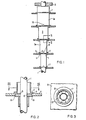
- FIG. 1 there is shown a portion of a heat exchanger tube 1 over which a heat flux limiting sleeve 3 is disposed adjacent an upper tubesheet 5.
- the sleeve 3 is larger in diameter on one end, the upper end, than it is on the other end, the lower end.
- An outwardly extending flange 7 is disposed adjacent the upper end of the sleeve 3 and supports the sleeve 3 on one of several support plates 9 disposed along the length of the sleeve 3.
- the sleeve 3 consists of a plurality of generally cylindrical portions 3a graduated in diameter, the upper cylindrical portions 3a being larger in diameter than the lower cylindrical portions 3a.
- Figs. 2 and 3 these are provided collars 11, which are disposed between adjacent cylindrical portions 3a.
- the collars 11 allow for axial expansion between adjacent cylindrical portions 3a and are counterbored from each end to receive the respective cylindrical portions 3a.
- a land 13 is disposed between the counterbores and has grooves 15 disposed therein for the passage of fluid from one cylindrical portion to the adjacent cylindrical portion.
- the land 13 is only slightly larger in diameter than the tubes.
- Drain vent sluts 18 are provided in the cylindrical portions 3a or in the collars 11.
- the collars 11 also have an outwardly extending flange 17 disposed on the upper end thereof and the collars fit into a hole in the support plates 9. Stakes 19 as shown in Figure 3 may be provided for fastening the collar 11 in the support plates 9.
- the heat flux sleeves 3 hereinbefore described also have a wall thickness which decreases in the same direction as the diameter decreases.
- the inside diameter of the sleeves 3 may be constant, may vary in the same direction or in the opposite direction as the outside diameter to provide an effective, inexpensive, and reliable heat flux sleeve for a liquid metal steam generator.
Landscapes
- Engineering & Computer Science (AREA)
- Physics & Mathematics (AREA)
- Thermal Sciences (AREA)
- Mechanical Engineering (AREA)
- General Engineering & Computer Science (AREA)
- High Energy & Nuclear Physics (AREA)
- Life Sciences & Earth Sciences (AREA)
- Sustainable Development (AREA)
- Sustainable Energy (AREA)
- Heat-Exchange Devices With Radiators And Conduit Assemblies (AREA)
- Details Of Heat-Exchange And Heat-Transfer (AREA)
Claims (5)
Applications Claiming Priority (2)
| Application Number | Priority Date | Filing Date | Title |
|---|---|---|---|
| US06/230,554 US4537249A (en) | 1981-02-02 | 1981-02-02 | Heat flux limiting sleeves |
| US230554 | 1981-02-02 |
Publications (2)
| Publication Number | Publication Date |
|---|---|
| EP0057746A1 EP0057746A1 (fr) | 1982-08-18 |
| EP0057746B1 true EP0057746B1 (fr) | 1984-08-29 |
Family
ID=22865653
Family Applications (1)
| Application Number | Title | Priority Date | Filing Date |
|---|---|---|---|
| EP81107817A Expired EP0057746B1 (fr) | 1981-02-02 | 1981-10-01 | Manchons limitant le flux de chaleur |
Country Status (4)
| Country | Link |
|---|---|
| US (1) | US4537249A (fr) |
| EP (1) | EP0057746B1 (fr) |
| JP (1) | JPS57134696A (fr) |
| DE (1) | DE3165783D1 (fr) |
Families Citing this family (10)
| Publication number | Priority date | Publication date | Assignee | Title |
|---|---|---|---|---|
| US4619314A (en) * | 1983-08-05 | 1986-10-28 | Ishikawajima-Harima Jukogyo Kabushiki Kaisha | Device for preventing wear of heat transfer tubes in fluidized-bed boiler |
| US4529123A (en) * | 1983-09-02 | 1985-07-16 | Combustion Research Corporation | Radiant heater system |
| DE3706645A1 (de) * | 1987-03-02 | 1988-09-15 | Doerhoefer Dofa Kessel Und App | Waermetauscher |
| DE3715713C1 (de) * | 1987-05-12 | 1988-07-21 | Borsig Gmbh | Waermetauscher insbesondere zum Kuehlen von Spaltgasen |
| NL194891C (nl) * | 1993-11-24 | 2003-06-04 | Lentjes Standard Fasel Bv | Koelinrichting voor het koelen van een warm medium. |
| DE19645390C2 (de) * | 1996-11-04 | 2000-01-13 | Metallgesellschaft Ag | Mittel- oder Hochdruckwärmetauscher mit einer wärmedämmenden Verkleidung |
| EP1304159A1 (fr) * | 2001-10-19 | 2003-04-23 | Methanol Casale S.A. | Procédé et réacteur pour la mise en oeuvre de réactions chimiques sous des conditions pseudo-isothermiques |
| DE102008018931A1 (de) | 2007-04-17 | 2008-11-13 | Gyrus ACMI, Inc., Southborough | Lichtquellenleistung auf der Grundlage einer vorbestimmten erfaßten Bedingung |
| KR20120042713A (ko) | 2009-02-04 | 2012-05-03 | 퍼듀 리서치 파운데이션 | 금속 수소화물 저장 시스템용 코일형 마이크로채널 열교환기 |
| JP2012516984A (ja) * | 2009-02-04 | 2012-07-26 | パーデュ リサーチ ファンデーション | 金属水素化物貯蔵システム用の羽根付き熱交換器 |
Family Cites Families (13)
| Publication number | Priority date | Publication date | Assignee | Title |
|---|---|---|---|---|
| US1762467A (en) * | 1928-01-13 | 1930-06-10 | Metalcraft Heater Corp | Automobile heater and the silencing of automobile heaters |
| US2315792A (en) * | 1941-04-21 | 1943-04-06 | Arthur B Hoss | Adapter |
| US2420373A (en) * | 1944-09-15 | 1947-05-13 | Us Steel Corp Of Delaware | Hot-blast stove |
| US3132691A (en) * | 1959-02-06 | 1964-05-12 | Babcock & Wilcox Co | Heat exchanger construction and thermal shield therefor |
| CH398763A (de) * | 1963-02-21 | 1966-03-15 | Bbc Brown Boveri & Cie | Magnetogasdynamischer Generator mit gekühlten Kanalwänden |
| GB1225967A (fr) * | 1967-03-22 | 1971-03-24 | ||
| NL6807673A (fr) * | 1968-05-30 | 1969-12-02 | ||
| BE760718A (fr) * | 1970-01-22 | 1971-05-27 | Babcock Atlantique Sa | Perfectionnements aux generateurs de vapeur |
| FR2097056B1 (fr) * | 1970-07-30 | 1974-09-20 | Chausson Usines Sa | |
| US3743252A (en) * | 1972-03-16 | 1973-07-03 | Gloucester Eng Co Inc | Air cooled extruder |
| GB1431785A (en) * | 1972-12-22 | 1976-04-14 | Atomic Energy Authority Uk | Heat exchangers |
| US3982901A (en) * | 1975-06-25 | 1976-09-28 | Dorr-Oliver Incorporated | Heat transfer element and tuyere for fluidized bed reactor |
| SU821897A1 (ru) * | 1979-06-25 | 1981-04-15 | Новополоцкий политехнический институт | Теплообменный элемент типа"ТРубА B ТРубЕ |
-
1981
- 1981-02-02 US US06/230,554 patent/US4537249A/en not_active Expired - Fee Related
- 1981-10-01 EP EP81107817A patent/EP0057746B1/fr not_active Expired
- 1981-10-01 DE DE8181107817T patent/DE3165783D1/de not_active Expired
- 1981-10-01 JP JP56154932A patent/JPS57134696A/ja active Pending
Also Published As
| Publication number | Publication date |
|---|---|
| DE3165783D1 (en) | 1984-10-04 |
| US4537249A (en) | 1985-08-27 |
| EP0057746A1 (fr) | 1982-08-18 |
| JPS57134696A (en) | 1982-08-19 |
Similar Documents
| Publication | Publication Date | Title |
|---|---|---|
| EP0015510B1 (fr) | Dispositif pour réduire le flux de chaleur local à travers un tube d'échangeur de chaleur | |
| US4909316A (en) | Dual-tube heat pipe type heat exchanger | |
| EP0057746B1 (fr) | Manchons limitant le flux de chaleur | |
| US4709756A (en) | Steam generator tube support | |
| EP0013796A1 (fr) | Echangeur de chaleur avec des tubes à double paroi pour détecter les fuites | |
| JPS6037389B2 (ja) | 液体分配器 | |
| US4226283A (en) | Multitubular heat exchanger | |
| US2956787A (en) | Heat interchanger | |
| US4157114A (en) | Tubesheet with a thermal sleeve | |
| KR850004799A (ko) | 내부식성 증기 발생기 | |
| GB969036A (en) | Improvements in or relating to tubular heat exchange apparatus | |
| GB1262377A (en) | Heat exchanger for production of steam | |
| US3251404A (en) | Liquid metal heated steam generator | |
| GB1220867A (en) | Tubular heat exchange assembly | |
| JPH076754B2 (ja) | 熱交換器 | |
| CA1277312C (fr) | Dispositif refroidisseur d'elements a paroi epaisse, plus particulierement les plaques a tubulure des echangeurs thermiques | |
| US3176761A (en) | Heat exchanger | |
| JPS59112197A (ja) | 熱交換器 | |
| SU139417A1 (ru) | Нагревательный прибор дл систем центрального отоплени | |
| JPS5553698A (en) | Finned tube type heat exchanger | |
| JPS60243494A (ja) | 熱交換器 | |
| EP0122667A1 (fr) | Echangeur de chaleur et chaudière de chauffage central avec un tel échangeur de chaleur | |
| JPS6383692A (ja) | ヒ−トパイプ型原子炉 | |
| FR2287668A1 (fr) | Dispositif de protection thermique pour echangeur de chaleur | |
| SU819554A1 (ru) | Теплообменный элемент |
Legal Events
| Date | Code | Title | Description |
|---|---|---|---|
| PUAI | Public reference made under article 153(3) epc to a published international application that has entered the european phase |
Free format text: ORIGINAL CODE: 0009012 |
|
| AK | Designated contracting states |
Designated state(s): BE DE FR GB NL |
|
| 17P | Request for examination filed |
Effective date: 19830202 |
|
| GRAA | (expected) grant |
Free format text: ORIGINAL CODE: 0009210 |
|
| PGFP | Annual fee paid to national office [announced via postgrant information from national office to epo] |
Ref country code: DE Payment date: 19840821 Year of fee payment: 4 |
|
| AK | Designated contracting states |
Designated state(s): BE DE FR GB NL |
|
| PGFP | Annual fee paid to national office [announced via postgrant information from national office to epo] |
Ref country code: FR Payment date: 19840925 Year of fee payment: 4 |
|
| PGFP | Annual fee paid to national office [announced via postgrant information from national office to epo] |
Ref country code: BE Payment date: 19840930 Year of fee payment: 4 |
|
| REF | Corresponds to: |
Ref document number: 3165783 Country of ref document: DE Date of ref document: 19841004 |
|
| ET | Fr: translation filed | ||
| PLBE | No opposition filed within time limit |
Free format text: ORIGINAL CODE: 0009261 |
|
| STAA | Information on the status of an ep patent application or granted ep patent |
Free format text: STATUS: NO OPPOSITION FILED WITHIN TIME LIMIT |
|
| 26N | No opposition filed | ||
| PGFP | Annual fee paid to national office [announced via postgrant information from national office to epo] |
Ref country code: NL Payment date: 19871031 Year of fee payment: 7 |
|
| PG25 | Lapsed in a contracting state [announced via postgrant information from national office to epo] |
Ref country code: GB Effective date: 19881001 |
|
| PG25 | Lapsed in a contracting state [announced via postgrant information from national office to epo] |
Ref country code: BE Effective date: 19881031 |
|
| BERE | Be: lapsed |
Owner name: WESTINGHOUSE ELECTRIC CORP. Effective date: 19881031 |
|
| PG25 | Lapsed in a contracting state [announced via postgrant information from national office to epo] |
Ref country code: NL Effective date: 19890501 |
|
| NLV4 | Nl: lapsed or anulled due to non-payment of the annual fee | ||
| PG25 | Lapsed in a contracting state [announced via postgrant information from national office to epo] |
Ref country code: FR Free format text: LAPSE BECAUSE OF NON-PAYMENT OF DUE FEES Effective date: 19890630 |
|
| PG25 | Lapsed in a contracting state [announced via postgrant information from national office to epo] |
Ref country code: DE Effective date: 19890701 |
|
| GBPC | Gb: european patent ceased through non-payment of renewal fee | ||
| REG | Reference to a national code |
Ref country code: FR Ref legal event code: ST |