EP0015525A1 - Adapteur de connexion électrique en combinaison avec un appareil - Google Patents
Adapteur de connexion électrique en combinaison avec un appareil Download PDFInfo
- Publication number
- EP0015525A1 EP0015525A1 EP80101048A EP80101048A EP0015525A1 EP 0015525 A1 EP0015525 A1 EP 0015525A1 EP 80101048 A EP80101048 A EP 80101048A EP 80101048 A EP80101048 A EP 80101048A EP 0015525 A1 EP0015525 A1 EP 0015525A1
- Authority
- EP
- European Patent Office
- Prior art keywords
- plug
- socket
- front unit
- switching
- electrical
- Prior art date
- Legal status (The legal status is an assumption and is not a legal conclusion. Google has not performed a legal analysis and makes no representation as to the accuracy of the status listed.)
- Granted
Links
Images



Classifications
-
- H—ELECTRICITY
- H01—ELECTRIC ELEMENTS
- H01H—ELECTRIC SWITCHES; RELAYS; SELECTORS; EMERGENCY PROTECTIVE DEVICES
- H01H43/00—Time or time-programme switches providing a choice of time-intervals for executing one or more switching actions and automatically terminating their operation after the programme is completed
- H01H43/02—Details
- H01H43/022—Bases; Housings; Mountings
Definitions
- the present invention relates to an electrical plug-in device with a plug plunger that fits in power sockets, a socket consisting of a plug socket block and plug cup, and with a switching device that is structurally combined between the connections of the plug plunger and the socket, in a housing with a front and rear, and a connecting side wall.
- a switching device that is structurally combined between the connections of the plug plunger and the socket, in a housing with a front and rear, and a connecting side wall.
- a short-term clock according to DE-GM 18 94 373 has a plug part in an essentially cylindrical housing at one end and a socket part at the opposite end. In another, this housing. Part of the housing part penetrating at a right angle is a timer switch with adjustment knob.
- the object of the present invention is to improve the structure and the housing of a plug-in device of the type relevant here in such a way that it can be adapted to the various regulations of the countries of use without significant changes in production, and also for the installation of various switching devices. and / or display devices with suitable or necessary operating elements is suitable.
- the arrangement of the front display and / or control elements and also the socket connection the latter usually down, without affecting the bracket quality and without additional structural change measures using only simple tools - regardless of the more or less random plug arrangement (vertical or horizontal) of a socket intended for connection - can be selected.
- the structural changes should be limited to the smallest possible part, even as far as possible, with the exception of the housing itself.
- a plug-in device according to the preamble of claim 1 in that the housing is mounted with at least the rear side with an in particular integrally molded pipe socket, in which the plug piston is rotatably and snap-fitted at an angular position and symmetrically opposite thereto, angularly offset stops , and a connecting side wall-containing rear part and a front unit suitably designed thereon with display and / or operating units mounted on the front side and formed around the axis of the plug piston prismatic shape.
- the plug piston is used interchangeably in the pipe socket in various plug equipment and / or by means of a protruding the wall of the pipe socket and in grooves on the inside surface this wall latching, in particular with the protective conductor or earthing bracket combined clamping bracket in preferred angular positions, preferably in three offset by 9 0 °, held with two connector pins in a position parallel to a connecting wall of the housing and is guided lockable.
- the axes of the plug piston arranged on the rear and the socket held in a connecting side wall enclose a right angle on the one hand and the front with the axis of the socket form an acute angle on the other. This ensures that the display and / or control elements in the front unit are clearly visible and recognizable both from above and from below.
- the principle of the versatile adaptation to different connection regulations that can be achieved with simple constructional means can be exploited in improved improvement if the socket is equipped with a protective conductor or earthing clip that can be plugged onto the bottom of the plug cup and by means of a molded-on lateral and rear edge projection with a groove for a matching cut-out edge attached to the associated wall on the one hand and / or guiding lugs for guiding grooves on the inside of the connecting side walls formed on the inside of the connector side and interchangeably guided and held, as well as by the overlying front unit is secured against falling out.
- the distance between the outer surface of the wall of the pipe socket and the connecting side wall with the socket is at least approximately one gap larger than the height of the plug socket including the protective conductor or earthing clip and the pipe socket for the plug piston at the edge of the connector cup protrudes.
- sleeve pieces are formed on the bottom of the connector cup with lateral openings, into which the female contacts can be inserted with protruding terminal lugs, and with rear openings into which spring clips on the female springs can be inserted to secure them against falling out .
- the prismatic rear part of the housing has a rectangular cross section around the axis of the plug piston and / or the front unit has a circular wall attachment for the front-mounted parts of the switching and / or Contains display device which is adapted by means of a bevel zone to the connecting side walls of the housing and / or the front unit on the rear side contains the other components of the switching and / or display device.
- the front unit has cutouts on the upper connecting side wall of its base plate, which plunges into the prismatic part of the housing, with a surface that fits on the underside of the prismatic part of the housing for lugs on the latter, as well as on the remaining parts of the connecting side wall, stop lugs to rest on the upper edge of the prismatic part, and at the points opposite the webs with guide and mounting holes have columns for screw threads.
- a wide range of electrical devices be it original, ie. from scratch in the first production, or by a conversion - so that their respective important components, such as connection, display and setting devices, as well as possibly operating equipment, take up little space and require little working time for assembly.
- a design with multi-coordinated assemblies if a counter with a numerical display for power or power consumption and / or operating hours is used as the electrical device, at least the elements for the numerical display are installed in the front unit on the front. If, instead or in addition, a measuring device for the instantaneous value of the current or power consumption with analog and / or digital display is installed, then at least its means for display in the front unit can be installed on the front.
- the electrical device to be installed is a time drive with jump excitation in one loading drive state of the switching device and delayed transition to the other operating state by an inhibitor known per se
- at least adjustment means for the delay and / or display means for the operating state in the front unit can be installed in the sense and in accordance with the teaching of the features described above.
- a motor for driving a switching disc to be put into circulation with switching elements that can be preset according to a circulation-periodic program is used on its circumference for actuating the switching device
- the front unit on the inside, together with an over-molded pillar fastens the drive motor, the transmission, the snap-action switching device and the mounting for its protruding to the outside, running on the circumference of the switching disc or its switching segments Shift lever contains.
- Fig. 1 is mounted on the rear 1 of the rear part 2 of the housing of the plug device 3 of the plug plunger 4, in which the front view of the housing 2 in Fig.la connecting side wall 5, the socket 6 with three sockets, one of which 6a May serve as a grounding socket and two 6b as power connections, pluggable onto the edge 7a cut out from the underside 7 and secured against falling out by the overlying front unit 8 with the pointer mechanism 19, 2o in front of the scales 9, lo of different division.
- the axis 11 of the plug piston 4 arranged on the rear side 1 and the axis 12 of the socket 6 form a right angle 13, the axes 12 and the front side 14 form an acute angle 15.
- the front unit 8 has, moreover, a circular wall attachment 16 for the front-mounted parts of the switching and / or display device, here the bearing 17 for the invisible shift lever with adjusting device, the previously mentioned scales 9, lo with the pointer mechanism 2 0 , 12, as well as the setting pinion drive 21 for setting initial or setpoint values.
- On the circumference of the circle there are adjusters 22 to 25 for limit values, when exceeded the actuating or display device triggers the switching device.
- a programmable digital counter of the actuating or display device programming buttons 26, 27, the illuminated numeric field 28 and operating mode selector buttons 29 are installed in the front of the front unit.
- the drawing of Fig.1 already shows the basic idea of the invention and the resulting technical progress that due to the attachment of the socket 8 immediately close to the bottom 5, since the plug piston 4 almost up to the stop of the back 1 in the Plugs in the mains socket, this underside 5 rests so directly on the mains socket that the tensile force of the unsigned cable with the plug which is plugged into the socket 6 is without an annoying tilting moment from the plug piston, ie. without any risk of loosening the connector.
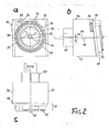
- the front side of the front unit 31 is shown in more detail in FIG. 2, so that the switching elements 32 that can be preset on the circumference of a switching periodic program for the actuation of the switching device, not shown, via the switching lever with switching finger 34 guided in the bearing 33 scanned switching disc together with the within the switching elements 32 with circumferential 24-hour mark 35 still is more clearly recognizable.
- the switching elements 32 are designed as circular ring segments which can be radially shifted in grooves 36 between two stop positions;
- any other switching disk arrangement can be used without further ado, which according to the setting or training made on the circumference of a circle according to the periodic program, possibly in Interact with another, e.g. concentric switching disc or more for a multi-pitch program with preprogrammed decommissioning of the main program or activation of short-term programs can be scanned in another way by time-controlled rotation or indexing.
- the front unit 31 with the circular wall attachment 37 has at the lower edge the bevel zone 38, by means of which such an adaptation to the connecting side walls 39-41 is achieved that the reduction in size caused by the circular wall attachment 37 still supports and nevertheless a reliable mounting in particular the socket installed flush on the underside 42 (not shown here) is ensured by the front unit 31 resting on the connecting side walls and a mixed snap and screw fastening to be described.
- the slider 46 projecting therethrough can still be seen, with which a built-in shift lever or other means of the switching and / or display device can be locked in one of the operating positions.
- the configuration of the plug piston 45 with guide grooves 47 and therein protective conductor contact 48 and guide webs 49 on cut surfaces can be recognized in accordance with the relevant regulations of the German Federal Republic.
- the fixed 12-hour dial 5o with the clockwork consisting of minute 51 and hour hand 52 for the time of day is attached in a circular recess, on the axis of which is known per se Hollow shafts the setting pinion 53 is set for setting the time of day and switching disc.
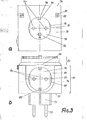
- FIG. 3 shows details of the plug piston 71 and the socket 72 - in connection with their installation in the housing of the plug device according to the invention, ie. in the rear wall 73 and in the lower connecting side wall 74 - reproduced.
- the plug piston 71 With the plug piston 71, one can see the previously mentioned guide webs 75 on cut surfaces 76, the actual power connection pins 77, the guide grooves 78 with protective conductor contact spring 79 and a neutral conductor socket 80.
- countersunk holes 81 of the rear wall 37 there are screws 82 for the connection the front unit 83 sunk with the rear part 84 of the housing in guide webs, not shown here.
- the offset edge 85 is attached in such a way that the socket 72 with a flush closure in the bottom can be plugged onto it can.
- the front unit 83 is cut accordingly at its lower edge 86 visible in FIG. 3b for the connector cup.
- the socket 72 has, in a reciprocal manner with respect to the plug piston 71, guide grooves 87 on cut surfaces 88, protective conductor contact springs 89 and current connection sockets 90.
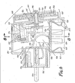
- FIG 4 a kind of longitudinal section through the embodiment of the plug-in device, the four main groups are to be distinguished first, the housing, from which the rear wall lol and the upper connecting wall lo2 are clearly visible, the socket lo3 with socket block 104 and plug cup 105, the Plug piston lo6, which is both rotatably and interchangeably inserted in the pipe socket 107 formed on the rear wall 101, and finally the front unit 108 with the circular wall attachment 109 mounted on the front and the printed circuit board 110 attached to the inside via molded columns for the drive motor (not shown), the gear shown in parts 111 with a partially flat design with multiple worm gear 112 and the other parts hidden here.
- the front unit 108 is still the construction of the switching disc with the radially displaceable switching elements 114 which engage in notches 113, the setting pinion drive 116 connected in one piece with the minute hand 115, the hour hand 117, the guide grooves 118 in the carrier disk 119 with integrally formed gear wheel 12o and the pinion gear 121 reproduced in detail for the time of day hand mechanism, the latter being connected to the gear 111 and the gear 122 via a worm gear with that of the drive motor.
- a component of the basic inventive concept of the plug device therefore also consists in the most compact possible construction of the built-in electrical device for the switching and / or display device, here preferably using multiple worm gears lying flat in cross design.
- the protective conductor or earthing bracket 123 is also worth mentioning, which is simply plugged onto pins 125 formed on the bottom lo4 of the plug socket 105 and, however, due to the lower edge of the pipe socket lo7, which is at least approximately a gap 126 higher, and also through a nose 127 on the inside 128 of the front unit is secured against falling out.
- the plug plunger 106 is secured against falling out by the protective conductor or grounding bracket 129 connected to the plug plunger 106 from the inside by means of the screw 129a with the protective conductor contact spring 13o by means of the clamping bracket 131 projecting beyond the pipe socket 107; the protective conductor or earthing bracket 123 and that 129 are connected to one another by the line 132.
- the pipe socket lo6 has on its inner edge surface 133 at a middle and symmetrically opposite to each other offset by 90 ° grooves in which the protruding tab of the clamping bracket 131 of the protective conductor or earthing bracket 129 engages latching, so that the connector piston rotates so defined can be that the connector pins 134 either horizontally, possibly rotated by 180 °, or can be inserted vertically into a power outlet. In this way, the connector can once the more or less random installation of a power outlet with a vertical or horizontal book. senunion and on the other to be adapted for use in the upper or lower region of the wall height, the front unit being conveniently turned on from above or from below can be seen.
- Fig. 5a (left) is again the front side with the switching elements 202 radially displaceable in grooves 201 and the switching disc formed from these and the carrier disc formed as a circumferential ring with 24-hour marking 203, the time of day pointer mechanism 204 and the protruding one Bearing 2o5 for the shift finger 2o6 of the invisible shift lever, which covers the circumference of the switching disk or its switching elements.
- FIG. 5a (left) is again the front side with the switching elements 202 radially displaceable in grooves 201 and the switching disc formed from these and the carrier disc formed as a circumferential ring with 24-hour marking 203, the time of day pointer mechanism 204 and the protruding one Bearing 2o5 for the shift finger 2o6 of the invisible shift lever, which covers the circumference of the switching disk or its switching elements.
- the connector cup 227 is shown with a molded socket block 228, in the sleeve pieces 229 of which there are lateral openings.23o the contact socket springs 231 with protruding terminal lugs 232 can be inserted by means of spring clips 233 with eyelets in the rear openings 234 so that they are secured against falling out of the openings 23o.
- the inside edge surface 235 with grooves 236 can be seen for latching engagement of the protruding flap of the clamping bracket 237, which is connected from the inside by the screw 238 to the plug piston (only partially visible).
- the connector cup is by means of the groove 239 in the offset edge 240 of the lower side wall 241, and by means of the guide lugs 242 in the grooves 243 of the pillars formed as molded projections 244 with a countersunk hole 245 for a screw (not visible here) for fastening the front unit flush with the Bottom 246 inserted.
- this cup part needs to be modified accordingly.
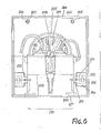
- Fig. 6 is the installation of the interchangeably plugged socket 251 with plug cup 252 and sockets block 253 on the one hand and in the molded pipe socket.
- 254 is shown in front view after the front unit has been removed by means of a protective conductor or grounding bracket 255 and screw 256 which can be rotated and exchangeably held after removal of the front unit.
- the plug-in guides are visible as uncut on the plug cup 252 integrally formed groove walls 257, 258 on the one hand and web wall 259, the latter being guided in the groove 261 formed on the inner wall projection 26o and the wall projection 26o being designed with a tapered hole 262 on the front , behind which the larger countersunk hole 263 for the screw head is indicated by dashed lines.
- the lugs 265, 266 are attached, which snap into corresponding openings on the inside of the front unit, and in their vicinity the molded pins 267, 268 for the spacing of parts on the rear wall of the front unit.
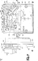
- Fig. 7a shows the front unit in side view, so that the board 3o2 fastened via pillars 301 formed on the inside with its also molded bearing blocks 303, 3o4 and the bearing wall 305, as well as the also molded threaded connector 3o6 for the attachment of the rear one. Can see part of the housing forth.
- the circular wall attachment on the front is designated 3o7, the bevel zone with 3o8 and a circumferential side wall strip set back on the inside 3o9 with 310.
- the shaft 318 which is driven via the worm drive 315 by the armature 316 of the motor with the stator 317, and that of the latter also mounted via a worm gear 319 driven shaft 32o, which in turn uses the worm gear 321 via the further gear part 322 to shift disc and drives the time of day hands.
- the snap-action switching device with shift lever 323 can be seen, which actuates the actual contact arm 325 via the intermediate lever 324 acted upon by it, the contact 326 of which is pressed onto the counter-contact 327 by the tension spring 328 when the intermediate lever 324 is acted upon, even with a small force, exceeds its tilt point, so that the contacts are pressed against one another by the spring with a substantially greater force.
- the shift lever 323 is acted upon intermittently via a shift finger protruding through the opening 329 (2o6 in FIG. 5) according to the program on the circumference of the switching disk or by the slide 33o into a continuous operating position in which the program is not effective. This slide actuation can be adjusted with the eccentric screw 331.
- the curve sections 332 correspond to the cutouts (86 in FIG. 3) for the edge of the connector cup.
- Fig. 8 shows a front view or a section C-C in Fig. 7b of the front unit, if one understands the representation of Fig. 7b as a plan.
- the stator 333 of the motor carries the winding 334.
- the above-described exemplary embodiment of the plug pre-mixing is merely a - albeit particularly illustrative - special case of many possible applications of the basic inventive concept of the interchangeable assembly of the socket and the plug piston in connection with an electrical device - here a timer - for the actuation of a circuit between the connections of the plug piston and socket acting switching and / or display Facility.
Landscapes
- Details Of Connecting Devices For Male And Female Coupling (AREA)
Priority Applications (1)
| Application Number | Priority Date | Filing Date | Title |
|---|---|---|---|
| AT80101048T ATE3795T1 (de) | 1979-03-05 | 1980-03-03 | Zwischenstecker-geraete-kombination. |
Applications Claiming Priority (2)
| Application Number | Priority Date | Filing Date | Title |
|---|---|---|---|
| DE19792908597 DE2908597A1 (de) | 1979-03-05 | 1979-03-05 | Elektrische steckvorrichtung mit steckerkolben, steckdose, sowie elektrischem geraet fuer die betaetigung einer stell- und/oder schalt- und/oder anzeigeeinrichtung |
| DE2908597 | 1979-03-05 |
Publications (2)
| Publication Number | Publication Date |
|---|---|
| EP0015525A1 true EP0015525A1 (fr) | 1980-09-17 |
| EP0015525B1 EP0015525B1 (fr) | 1983-06-15 |
Family
ID=6064572
Family Applications (1)
| Application Number | Title | Priority Date | Filing Date |
|---|---|---|---|
| EP80101048A Expired EP0015525B1 (fr) | 1979-03-05 | 1980-03-03 | Adapteur de connexion électrique en combinaison avec un appareil |
Country Status (3)
| Country | Link |
|---|---|
| EP (1) | EP0015525B1 (fr) |
| AT (1) | ATE3795T1 (fr) |
| DE (1) | DE2908597A1 (fr) |
Cited By (10)
| Publication number | Priority date | Publication date | Assignee | Title |
|---|---|---|---|---|
| GB2159346A (en) * | 1984-05-01 | 1985-11-27 | Chi Chuen Chow | Timing device for a plug, socket or socket connector |
| GB2181899A (en) * | 1985-08-21 | 1987-04-29 | Bass Plc | Electronic switches |
| GB2197546A (en) * | 1986-07-29 | 1988-05-18 | Festo Kg | Electrical connectors |
| GB2199705A (en) * | 1987-01-09 | 1988-07-13 | Mark William Meakings | An electrical plug incorporating a time switch |
| EP0249907A3 (en) * | 1986-06-20 | 1989-07-26 | Diehl Gmbh & Co. | Housing system for electrical apparatuses |
| ES2114486A1 (es) * | 1996-04-01 | 1998-05-16 | Ribera Farinos Alfredo | Procedimiento para la union de piezas porosas. |
| GB2331187A (en) * | 1997-11-05 | 1999-05-12 | Well Shin Enterprise Co Ltd | Charger with a range of plugs |
| EP2704103A1 (fr) * | 2012-08-29 | 2014-03-05 | Werner Schnabel | Compteur d'énergie et consommateur électrique |
| CN107611705A (zh) * | 2017-10-18 | 2018-01-19 | 广州知崇新能源科技有限公司 | 转换连接用插头 |
| CN117374681A (zh) * | 2023-12-07 | 2024-01-09 | 深圳市瑞祥达电子有限公司 | 一种多功能数据线 |
Families Citing this family (1)
| Publication number | Priority date | Publication date | Assignee | Title |
|---|---|---|---|---|
| DE102022116567A1 (de) * | 2022-07-04 | 2024-01-04 | Schneider Electric Industries Sas | Steuerbare Leistungsschaltvorrichtung, Leistungsschaltverfahren, Steckdose, Verbraucherinstallation |
Citations (6)
| Publication number | Priority date | Publication date | Assignee | Title |
|---|---|---|---|---|
| US3522393A (en) * | 1968-07-26 | 1970-07-28 | Intern Register Co | Time switch |
| DE2208445A1 (de) * | 1972-02-23 | 1973-08-30 | Walter Dipl Ing Rich | Netzstrombetriebene elektrische schaltuhr zum uhrzeitabhaengigen schalten der stromzufuhr netzstrombetriebener elektrischer geraete |
| DE7611675U1 (de) * | 1976-04-13 | 1976-08-12 | Dieter Graesslin Feinwerktechnik, 7742 St Georgen | Anordnung für Schaltuhren |
| US3996546A (en) * | 1975-02-19 | 1976-12-07 | The Gillette Company | Plug for voltage adaptation |
| DE7717780U1 (de) * | 1977-06-04 | 1978-08-03 | Dieter Graesslin Feinwerktechnik, 7742 St Georgen | Einrichtung für Zeitschaltgeräte |
| DE7828557U1 (de) * | 1978-09-22 | 1979-02-15 | Suevia Uhrenfabrik Gmbh, 7032 Sindelfingen | Elektronische Steckdosen-Schaltuhr |
Family Cites Families (6)
| Publication number | Priority date | Publication date | Assignee | Title |
|---|---|---|---|---|
| CH221708A (fr) * | 1941-07-23 | 1942-06-15 | Philippe Giroud Henri | Thermostat. |
| DE1737574U (de) * | 1956-10-20 | 1957-01-10 | Eisen & Stahlind Ag | Temperaturfuehlergeraet. |
| DE1894373U (de) * | 1963-08-01 | 1964-06-11 | Franz Johann Jakob Mueller | Elektrischer-ausschaltautomat. |
| SE335764B (fr) * | 1968-11-27 | 1971-06-07 | Lumalampan Ab | |
| DE7112994U (de) * | 1971-04-03 | 1971-07-08 | Heil O Ohg | Geraetesteckdose mit verriegelungselementen |
| DE2701524A1 (de) * | 1977-01-15 | 1978-07-20 | Graesslin Feinwerktech | Elektrischer thermostatschalter |
-
1979
- 1979-03-05 DE DE19792908597 patent/DE2908597A1/de active Granted
-
1980
- 1980-03-03 EP EP80101048A patent/EP0015525B1/fr not_active Expired
- 1980-03-03 AT AT80101048T patent/ATE3795T1/de active
Patent Citations (6)
| Publication number | Priority date | Publication date | Assignee | Title |
|---|---|---|---|---|
| US3522393A (en) * | 1968-07-26 | 1970-07-28 | Intern Register Co | Time switch |
| DE2208445A1 (de) * | 1972-02-23 | 1973-08-30 | Walter Dipl Ing Rich | Netzstrombetriebene elektrische schaltuhr zum uhrzeitabhaengigen schalten der stromzufuhr netzstrombetriebener elektrischer geraete |
| US3996546A (en) * | 1975-02-19 | 1976-12-07 | The Gillette Company | Plug for voltage adaptation |
| DE7611675U1 (de) * | 1976-04-13 | 1976-08-12 | Dieter Graesslin Feinwerktechnik, 7742 St Georgen | Anordnung für Schaltuhren |
| DE7717780U1 (de) * | 1977-06-04 | 1978-08-03 | Dieter Graesslin Feinwerktechnik, 7742 St Georgen | Einrichtung für Zeitschaltgeräte |
| DE7828557U1 (de) * | 1978-09-22 | 1979-02-15 | Suevia Uhrenfabrik Gmbh, 7032 Sindelfingen | Elektronische Steckdosen-Schaltuhr |
Cited By (13)
| Publication number | Priority date | Publication date | Assignee | Title |
|---|---|---|---|---|
| GB2159346A (en) * | 1984-05-01 | 1985-11-27 | Chi Chuen Chow | Timing device for a plug, socket or socket connector |
| GB2181899A (en) * | 1985-08-21 | 1987-04-29 | Bass Plc | Electronic switches |
| GB2181899B (en) * | 1985-08-21 | 1989-08-02 | Bass Plc | Electronic switches |
| EP0249907A3 (en) * | 1986-06-20 | 1989-07-26 | Diehl Gmbh & Co. | Housing system for electrical apparatuses |
| GB2197546B (en) * | 1986-07-29 | 1991-01-02 | Festo Kg | Electrical connectors |
| GB2197546A (en) * | 1986-07-29 | 1988-05-18 | Festo Kg | Electrical connectors |
| GB2199705A (en) * | 1987-01-09 | 1988-07-13 | Mark William Meakings | An electrical plug incorporating a time switch |
| ES2114486A1 (es) * | 1996-04-01 | 1998-05-16 | Ribera Farinos Alfredo | Procedimiento para la union de piezas porosas. |
| GB2331187A (en) * | 1997-11-05 | 1999-05-12 | Well Shin Enterprise Co Ltd | Charger with a range of plugs |
| EP2704103A1 (fr) * | 2012-08-29 | 2014-03-05 | Werner Schnabel | Compteur d'énergie et consommateur électrique |
| CN107611705A (zh) * | 2017-10-18 | 2018-01-19 | 广州知崇新能源科技有限公司 | 转换连接用插头 |
| CN117374681A (zh) * | 2023-12-07 | 2024-01-09 | 深圳市瑞祥达电子有限公司 | 一种多功能数据线 |
| CN117374681B (zh) * | 2023-12-07 | 2024-02-06 | 深圳市瑞祥达电子有限公司 | 一种多功能数据线 |
Also Published As
| Publication number | Publication date |
|---|---|
| DE2908597C2 (fr) | 1987-06-19 |
| EP0015525B1 (fr) | 1983-06-15 |
| DE2908597A1 (de) | 1980-09-25 |
| ATE3795T1 (de) | 1983-06-15 |
Similar Documents
| Publication | Publication Date | Title |
|---|---|---|
| DE3222237A1 (de) | Kippschalter | |
| EP0015525A1 (fr) | Adapteur de connexion électrique en combinaison avec un appareil | |
| DE2611154C3 (de) | Steckdosen-Schaltuhr | |
| EP0017124A1 (fr) | Appareil électrique, notamment appareil d'installation | |
| DE2835518C2 (de) | Elektrische Schaltuhr mit analoger Uhrzeitanzeige | |
| DE2510486C2 (fr) | ||
| DE2515196A1 (de) | Heizgeraet o.dgl. | |
| EP0081089A2 (fr) | Dispositif de commande programmable, en particulier pour appareils commutateurs à mesure de temps | |
| DE2432811A1 (de) | Synchronuhr mit elektrischer schalteinrichtung | |
| DE7906089U1 (de) | Elektrisches Zeitschaltgerät mit Steckerkolben, Steckdose, sowie zeitlich gesteuert ablaufendem Hebelwerk für die Betätigung einer Schaltereinrichtung | |
| DE2812267C3 (de) | Elektrische Schaltuhr | |
| DE1933976A1 (de) | Abstimmvorrichtung fuer HF-Nachrichten-UEbertragungsgeraete | |
| EP0464376B1 (fr) | Levier d'un interrupteur avec un dispositif pour l'ajustage du point de contact d'un commutateur électrique pour minuteries électromécaniques | |
| DE1665310A1 (de) | Potentiometer | |
| DE2618114A1 (de) | Vorrichtung zur anzeige der stellung von drehbaren mechanischen elementen | |
| EP0660206B1 (fr) | Interrupteur horaire | |
| DE2132855B2 (de) | Drehschalter | |
| EP4258307A1 (fr) | Appareil de technique d'installation domestique | |
| DE2651628A1 (de) | Elektrische zeitschalteinrichtung mit einem stecker und einer steckdose | |
| DE870432C (de) | Auf eine gewuenschte Schaltzeit einstellbares Geraet zum wahlweisen OEffnen und Schliessen eines elektrischen Stromkreises | |
| DE4034609A1 (de) | Multifunktionsschluesselschalter fuer ein reizstromgeraet fuer medizinische baeder | |
| DE3140934A1 (de) | "zeigermessgeraet" | |
| DE2945910A1 (de) | Elektronischer helligkeitsregler | |
| DE4445646C1 (de) | Elektrische Weckeruhr | |
| DE2262813A1 (de) | Schaltuhr fuer montage in unterputzdosen |
Legal Events
| Date | Code | Title | Description |
|---|---|---|---|
| PUAI | Public reference made under article 153(3) epc to a published international application that has entered the european phase |
Free format text: ORIGINAL CODE: 0009012 |
|
| AK | Designated contracting states |
Designated state(s): AT BE CH FR GB IT LU NL SE |
|
| 17P | Request for examination filed |
Effective date: 19810128 |
|
| ITF | It: translation for a ep patent filed | ||
| GRAA | (expected) grant |
Free format text: ORIGINAL CODE: 0009210 |
|
| AK | Designated contracting states |
Designated state(s): AT BE CH FR GB IT LU NL SE |
|
| PG25 | Lapsed in a contracting state [announced via postgrant information from national office to epo] |
Ref country code: SE Effective date: 19830615 Ref country code: NL Effective date: 19830615 Ref country code: BE Effective date: 19830615 |
|
| REF | Corresponds to: |
Ref document number: 3795 Country of ref document: AT Date of ref document: 19830615 Kind code of ref document: T |
|
| ET | Fr: translation filed | ||
| NLV1 | Nl: lapsed or annulled due to failure to fulfill the requirements of art. 29p and 29m of the patents act | ||
| PG25 | Lapsed in a contracting state [announced via postgrant information from national office to epo] |
Ref country code: LU Free format text: LAPSE BECAUSE OF NON-PAYMENT OF DUE FEES Effective date: 19840331 |
|
| PLBE | No opposition filed within time limit |
Free format text: ORIGINAL CODE: 0009261 |
|
| STAA | Information on the status of an ep patent application or granted ep patent |
Free format text: STATUS: NO OPPOSITION FILED WITHIN TIME LIMIT |
|
| 26N | No opposition filed | ||
| GBPC | Gb: european patent ceased through non-payment of renewal fee | ||
| GBDL | Gb: delete "european patent ceased" from journal |
Free format text: 5201,PAGE 3395 |
|
| PGFP | Annual fee paid to national office [announced via postgrant information from national office to epo] |
Ref country code: AT Payment date: 19900427 Year of fee payment: 11 |
|
| PGFP | Annual fee paid to national office [announced via postgrant information from national office to epo] |
Ref country code: CH Payment date: 19900626 Year of fee payment: 11 |
|
| PG25 | Lapsed in a contracting state [announced via postgrant information from national office to epo] |
Ref country code: AT Effective date: 19910303 |
|
| ITTA | It: last paid annual fee | ||
| PG25 | Lapsed in a contracting state [announced via postgrant information from national office to epo] |
Ref country code: CH Effective date: 19910331 |
|
| REG | Reference to a national code |
Ref country code: CH Ref legal event code: PL |
|
| PGFP | Annual fee paid to national office [announced via postgrant information from national office to epo] |
Ref country code: GB Payment date: 19960213 Year of fee payment: 17 |
|
| PGFP | Annual fee paid to national office [announced via postgrant information from national office to epo] |
Ref country code: FR Payment date: 19960328 Year of fee payment: 17 |
|
| PG25 | Lapsed in a contracting state [announced via postgrant information from national office to epo] |
Ref country code: GB Effective date: 19970303 |
|
| GBPC | Gb: european patent ceased through non-payment of renewal fee |
Effective date: 19970303 |
|
| PG25 | Lapsed in a contracting state [announced via postgrant information from national office to epo] |
Ref country code: FR Free format text: LAPSE BECAUSE OF NON-PAYMENT OF DUE FEES Effective date: 19971128 |
|
| REG | Reference to a national code |
Ref country code: FR Ref legal event code: ST |