EP0015559B1 - Dichtungsvorrichtung für eine Rohrverbindung - Google Patents
Dichtungsvorrichtung für eine Rohrverbindung Download PDFInfo
- Publication number
- EP0015559B1 EP0015559B1 EP19800101146 EP80101146A EP0015559B1 EP 0015559 B1 EP0015559 B1 EP 0015559B1 EP 19800101146 EP19800101146 EP 19800101146 EP 80101146 A EP80101146 A EP 80101146A EP 0015559 B1 EP0015559 B1 EP 0015559B1
- Authority
- EP
- European Patent Office
- Prior art keywords
- sleeve
- pipes
- sealing device
- end sections
- intermediate section
- Prior art date
- Legal status (The legal status is an assumption and is not a legal conclusion. Google has not performed a legal analysis and makes no representation as to the accuracy of the status listed.)
- Expired
Links
Images
Classifications
-
- F—MECHANICAL ENGINEERING; LIGHTING; HEATING; WEAPONS; BLASTING
- F16—ENGINEERING ELEMENTS AND UNITS; GENERAL MEASURES FOR PRODUCING AND MAINTAINING EFFECTIVE FUNCTIONING OF MACHINES OR INSTALLATIONS; THERMAL INSULATION IN GENERAL
- F16L—PIPES; JOINTS OR FITTINGS FOR PIPES; SUPPORTS FOR PIPES, CABLES OR PROTECTIVE TUBING; MEANS FOR THERMAL INSULATION IN GENERAL
- F16L55/00—Devices or appurtenances for use in, or in connection with, pipes or pipe systems
- F16L55/16—Devices for covering leaks in pipes or hoses, e.g. hose-menders
- F16L55/162—Devices for covering leaks in pipes or hoses, e.g. hose-menders from inside the pipe
- F16L55/163—Devices for covering leaks in pipes or hoses, e.g. hose-menders from inside the pipe a ring, a band or a sleeve being pressed against the inner surface of the pipe
-
- F—MECHANICAL ENGINEERING; LIGHTING; HEATING; WEAPONS; BLASTING
- F16—ENGINEERING ELEMENTS AND UNITS; GENERAL MEASURES FOR PRODUCING AND MAINTAINING EFFECTIVE FUNCTIONING OF MACHINES OR INSTALLATIONS; THERMAL INSULATION IN GENERAL
- F16L—PIPES; JOINTS OR FITTINGS FOR PIPES; SUPPORTS FOR PIPES, CABLES OR PROTECTIVE TUBING; MEANS FOR THERMAL INSULATION IN GENERAL
- F16L21/00—Joints with sleeve or socket
- F16L21/002—Sleeves or nipples for pipes of the same diameter; Reduction pieces
- F16L21/005—Sleeves or nipples for pipes of the same diameter; Reduction pieces made of elastic material, e.g. partly or completely surrounded by clamping devices
-
- F—MECHANICAL ENGINEERING; LIGHTING; HEATING; WEAPONS; BLASTING
- F16—ENGINEERING ELEMENTS AND UNITS; GENERAL MEASURES FOR PRODUCING AND MAINTAINING EFFECTIVE FUNCTIONING OF MACHINES OR INSTALLATIONS; THERMAL INSULATION IN GENERAL
- F16L—PIPES; JOINTS OR FITTINGS FOR PIPES; SUPPORTS FOR PIPES, CABLES OR PROTECTIVE TUBING; MEANS FOR THERMAL INSULATION IN GENERAL
- F16L21/00—Joints with sleeve or socket
- F16L21/02—Joints with sleeve or socket with elastic sealing rings between pipe and sleeve or between pipe and socket, e.g. with rolling or other prefabricated profiled rings
- F16L21/04—Joints with sleeve or socket with elastic sealing rings between pipe and sleeve or between pipe and socket, e.g. with rolling or other prefabricated profiled rings in which sealing rings are compressed by axially-movable members
Definitions
- This invention relates to a sealing device for forming a lining on the joint portions of pipes, comprising a tubular sleeve made of an elastic material and having end sections and an intermediate section between the end sections, said end sections of the sleeve being adapted to be brought into contact with the inner surfaces of the joint portions of the pipes, and expanding means provided in the corresponding inner surfaces of the end sections of the sleeve to cause the outer peripheral surfaces of the end sections of the sleeve to be pressed against the inner surfaces of the joint portions of the pipes.
- a sealing device of this kind is already known from British Patent No. 1,200,225 where a tubular sleeve is mounted on the inner surfaces of the joint portions of two adjacent pipes. Ring-like projections are provided on the outer peripheral surfaces of the end sections of the sleeve and pressed against the inner surfaces of the joint portions of the pipes by radially outwardly expanding ring members which are fitted in the inner surfaces of the sleeve. As a result, a certain extent of sealing is assured.
- the sealing device of this patent is not satisfactory under the following sitations. Where a great earthquake occurs, there is a possibility that the pipes will be exially relatively displaced at their joint portions, or bent, with resultant opening at the joint portions of the pipes. Under these situations, there is a risk that leakage of a gas flowing through the pipe will occur.
- DE-A-2.102.520 discloses a sleeve which has its periphery coated with an adhesive or impregnated with an adhesive.
- DE-A-2.063.110 discloses a sleeve made of elastic material which has an intermediate section which is thinner than its end sections.
- Pipes or ducts embedded in the ground suffer an inadvertent displacement during passage of a longer period due in part to the movement of the ground and the joint portions of the adjacent two pipes become slackened, involving a possible leakage of gas at the joint portions of the pipes. Under these situations, the sleeve is likely to be slipped out of the pipe along the inner surface of the pipe, causing gas leakage at the joint portions of the pipes.
- the object of this invention is to provide a sealing device for a pipe joint which can reduce the.possibility of leakage of a fluid such as a gas in a pipe if two adjacent pipes are displaced apart from each other at their joint portions.
- an elastic foamed body impregnated with an exudable binder is provided around the outer peripheral surface of each end section of the sleeve in a groove defined by a pair of flange-like projections or ridges provided on the outer peripheral surface of the respective end section so that the foamed body can be compressed by the expanding means against the inner surface of the joint portions of the pipes to cause the binder to be squeezed out of the foamed body to permit the end sections of the sleeve to be bonded to the inner surfaces of the joint portions of the pipes, and in that said intermediate section is thinner than said end sections and is expan- . sible in the axial direction of the sleeve.
- the exudable binder is impregnated in the foamed body it is easier for the operator to mount the sealing device on the inner surfaces of the joint portions of the pipes. For example, coating a liquid binder directly onto the inner surfaces of the joint portions of the pipes and/or the outer peripheral surfaces of the end sections of the sleeve to attain a bond between the sleeve and the pipes is very cumbersome and uniform bonding is difficult to obtain.
- the elastic foamed body impregnated with the exudable binder is provided around the entire outer periphery of each end section of the sleeve and, when pressure is applied to the elastic foamed body, the binder is uniformly squeezed out of the elastic foamed body throughout the entire circumference of the elastic foamed body and thus a uniform and positive bond can be effected between the pipe and the sleeve to assure an air-tight and water-tight seal.
- the elastic foamed body as used in this invention is of a type as shown, for example, in US patent no. 3,704,564.
- the intermediate section of the sleeve is made thinner than the end sections of the sleeve to permit sufficient expansion of the intermediate section of the sleeve.
- a strengthening insert piece may be embedded in the respective end sections of the sleeve to provide added stiffness to the end sections of the sleeve.
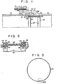
- the sealing device of this invention is mounted on the inner surfaces of the joint portions 17 of the pipes 15, 16 and has a tubular sleeve 22 formed of an elastic material such as synthetic rubber.
- the sleeve 22 has end sections 23, 23 and an intermediate section 24 therebetween.
- the intermediate section 24 of the sleeve is made thinner than the end sections 23, 23 of the sleeve 22 and constructed to have elasticity in the axial direction of the sleeve 22.
- a groove 27 for receiving an expanding ring 26 formed of a steel metal is defined by a pair of flanges 25, 25 in the inner surface of the end sections of the sleeve 22.
- a radially outwardly projecting, tapering sealing lip 28 is integrally formed on the outer peripheral surface of the sleeve 22 such that it is located immediately adjacent to the end face of the sleeve.
- a radially projecting smaller sealing lip 29 is formed at a location where the end section 23 of the sleeve 22 merges with the intermediate section 24 of the sleeve 22.
- a groove 31 for receiving a ring-like elastic foamed body or band 30 as set out below is formed on the outer peripheral surface of the end section 23 of the sleeve 22 such that it is defined between the sealing lips 28 and 29.
- the ring-like elastic foamed band 30 impregnated with an exudable or fluid flowable binder is wrapped around the outer peripheral surface of the groove 31 of the end section 23 of the sleeve 22.
- the foamed band 30 as used herein is an elastic synthetic resin as disclosed in US-A-3,704,564 and has continuous cells chemically stable against the impregnated binder.
- a binder use is made of one of well-known organic or inorganic binders.
- An epoxy resin binder settable at normal temperature is recommendable as a desired binder.
- the foamed band of a single band-like member rectangular in cross-section a plurality of members may be used as such and the cross-sectional configurations is not restricted to the rectangular cross-section. All that is necessary in this invention is for the binder to be able to be squeezed out over the whole length of the foamed band when pressure is applied.
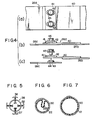
- the expanding ring 26 of a predetermined diameter as generally shown in Fig. 3 is manufactured by bending a band-like metal plate into a ring-like configuration and connecting the end portions 26b, 26c of the metal plate 26 together by a joint section 26a as shown in detail in Fig. 4(a) to 4(c).
- the ring 26 In the external force-free state, the ring 26 has a springy property and is smaller in diameter than the diameter of the ring in the state as shown in Fig. 3.
- a jig 35 as shown in Fig. 5 is used to connect the end portions 26b, 26c of the metal plate together with the metal plate 26 expanded as shown in Fig. 3.
- the jig 35 comprises a support ring 36 of a diameter smaller than that of the ring 26 in the external force-free state, externally threaded rods 37 threaded in the outer peripheral surface of the ring 36 such that they can be moved radially, and arcuate pushing members 38 each fixed on the outer end of the rod 37.
- the rod 37 can be rotated by operating the inner end of the rod 37 so as to move radially relative to the ring 36.
- the diameter of the ring 26 is expanded by inserting the jig 35 into the ring 26 in the external force-free state, operating the rods 37 to bring the pressing members 38 into contact with the inner surface of the ring 26, and radially outwardly uniformly pressing the members 38 against the inner surface of the ring 26.
- the end portions 26b, 26c of the ring 26 are connected together and then the jig 35 is withdrawn from the ring 26 with the pressing members 38 of the jig 35 radially inwardly retracted.
- a reinforcing plate 41 is welded to a plate 40 welded to one end portion 26b of the ring 26 and having the same width as that of the ring 26.
- a pair of elongated holes 42 are bored in each of the plates 40 and 41 and a pair of circular holes 43 are formed in the other end portion 26c of the ring 26.
- a nut 44 is welded to the other end portion of the ring 26 such that it aligns with the hole 43 of the ring 26.
- the end portion 26b of the ring 26 is secured to the other end portion 26c thereof by fitting the nuts 44 on the end portion 26b of the ring 26 into the corresponding holes 42 of the plates 40 and 41 and tightening bolts 45 into the corresponding nuts 44 on the end portion 26c of the ring 26.
- the diameter of the ring 26 so connected can be fine-adjusted within a range defined by the elongated hole 42.
- the sealing device so obtained is mounted on the inner surface of the joint portions of the pipes in the following manner.
- the operator takes the sealing device to a mounting site with the sleeve 22 and elastic foamed band 30 set as shown in Fig. 6. That is, the sleeve 22 has its diameter reduced with a loop 22a formed inside the sleeve 22 and the elastic foamed band 30 is wrapped around the outer peripheral surface of the end sections 23 of the sleeve 22. In this state, the end portions of the band 30 partially overlap each other as shown in Fig. 6. Since the exudable binder is already impregnated in the elastic foamed band 30, it is not unreasonably exuded, because no particular pressure is applied in this process. Therefore, the setting of the sealing device can be readily effected.
- the sealing device is carried by the operator inside the pipes and positioned with one end section 23 of the sleeve 22 set at one pipe 15 side and the other end section 23 at the other pipe 16 side.
- the joint portions of the pipes 15, 16 are internally covered by the intermediate section 24 of the sleeve 22 over the entire circumference thereof.
- the inner surfaces of the joint portions 17 of the pipes 15, 16 are beforehand polished and degreased through the entire circumference thereof.
- the sleeve 22 is expanded by the operator into a substantially circular form as shown in Fig. 7.
- the overlapped end portions of the elastic foamed band 30 are displaced relative to each other, leaving a smaller length of overlap.
- the band 30 is brought into close proximity to, or slightly contacted with, the inner surface of the joint portions of the pipes, and the ring 26 at its diameter-reduced state is fitted in the inner groove 27 of the sleeve 22.
- the diameter of the ring 26 is expanded by the jig 35 as shown in Fig. 5, causing the elastic foamed band 30 to be radially outwardly pressed against the inner surface of the pipes 15, 16 through the sleeve 22.
- the ring 26 has its end portions secured together by the bolt 45 through the joint section 26a, and then the jig 35 is withdrawn from the ring 26.
- the pair of sealing lips 28, 29 of the end section 23 are pressed against the corresponding inner surface of the pipes 15, 16 and elastically deformed, causing the band 30 to intimately close the outer groove 31 of the end sections 23, 23 of the sleeve 22.
- the elastic foamed band 30 is compressed to squeeze out the exudable binder to permit a clearance in the groove 31 to be filled with the binder.
- the binder is set after a predetermined time period and the end sections of the sleeve are bonded in an air-tight and water-tight fashion to the corresponding pipe portions so that the sleeve can not be moved in the axial direction.
- the sealing device of this invention is mounted on the inner surface of the joint portions 17 of the pipes 15, 16, there is a possibility that a gap 46 will be created between the abutting portions of the pipes by a shock, such as an earthquake, in the axial direction, or the joint portions of the pipes will be displaced in the axial direction to leave a clearance there.
- the intermediate section 24 of the sleeve 22 is expanded in the axial direction as indicated by arrows in Fig. 1 and elastically'deformed. Even if such an expansion and deformation occurs, the end sections of the sleeve remain fixed to the pipe portions. For this reason, there is no possibility of a gas leaking out through a possible clearance and thus a serious gas hazard is prevented from occurring.
- the intermediate section 24 of the sleeve 22 is formed thinner than the end sections 23, 23 thereof to provide an elastically deformable section, but the following method can be also adopted for this purpose.
- the rubber for the sleeve 22 can be vulcanized to such a varying extent that a soft property is given to the intermediate section 24 of the sleeve 22 and a hard property to the end sections 23, 23 of the sleeve 22.
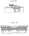
- a sealing device as shown in Figs. 8 and 9 includes a tubular sleeve 22 made of an elastic material such as synthetic resin, expanding rings 26, 26 made of a steel plate, and elastic, synthetic resin foamed bodies or bands 30, 30.
- the expanding ring 26 is received in a corresponding inner groove 27 which is defined by a pair of flanges 25, 25.
- An intermediate section 24 of the sleeve 22 is formed thinner than the end sections 23, 23 of the sleeve 22, and can be expanded in the axial direction of the sleeve 22.
- the sealing device is mounted on the inner surfaces of the joint portions 17 of pipes 15, 16 in the same way as in the first embodiment.
- the sealing device as shown in Figs. 8 and 9 . is different from the sealing device of Fig. 1 in the following respects.
- an outer groove 31 defined by a couple of sealing lips 28, 29 is formed on the outer periphery of each end section 23 of the sleeve 22 such that a plurality of flange-like radial projections or ridges 50, 51, 52, 53 spaced apart from each other are integrally formed on the entire circumference of the groove 31.
- a first group of projections 53 (four projections are shown by way of example) at the side of the intermediate projection 24 of the sleeve 22 has the same configuration and a height not exceeding a plane defined by the inner surface of the pipes as indicated by a dot-dash line in Fig.
- a second group of projections 50, 51, 52 (three projections are shown by way of example) has a different height.
- the projections 50, 51, 52 in said second group are arranged toward the intermediate section 24 of the sleeve in the increasing order of height as indicated by a dot-dash line in Fig. 9 and extended such that they exceed, like the outer lip 28, the plane defined by the inner surface of the pipes.
- An elastic foamed band 30 is wrapped around that portion of the groove 31 where the first group of projections 53 are located.
- the first group of projections 53 performs the function of causing the end section 23 of the sleeve 22 to be more firmly pressed onto the inner surface of the joint portions of the pipes and facilitating bonding by a binder which is squeezed out of the band 30.
- each of the end sections 23 of the sleeve 22 has a slightly projected or stepped surface portion where the band 30 is located.
- the sealing device is mounted on the inner surfaces of the joint portions 17 of the pipes 15, 16 and then, the end sections 23 of the sleeve are bonded to the inner surface of the pipes.
- the intermediate section 24 of the sleeve 22 is correspondingly elastically deformed, preventing leakage of a fluid flowing in the pipes 15, 16.
- a strengthening insert piece 54 formed of a metal network is embedded in the end sections 23, 23 of the sleeve 22.
- an added hardness or rigidity is given to the end section 23, 23 of the sleeve 22 and thus a higher bonding of the end sections 23, 23 of the sleeve 22 to the inner surfaces of the pipes are allowed.
- the use of such a strengthening insert piece 54 permits a choice of a softer material for the sleeve and allows a satisfactory elasticity of the intermediate section 24 of the sleeve.
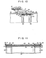
- Figs. 10 and 11 show a sealing device according to a third embodiment of this invention.
- like reference numerals are employed to designate parts or elements corresponding to those shown in the first embodiment and further explanation is omitted or a brief explanation will be made as necessary.
- a sealing device of Figs. 10 and 11 is mounted on the inner surface of the joint portions 17 of the pipes 15, 16 as shown in Fig. 10.
- this embodiment is fundamentally similar to the first embodiment except for an expansion preventing member 60 as will be described later. An explanation made in connection with the arrangement and function of the first embodiment holds true for this third embodiment.
- the above-mentioned expansion preventing member 60 is ring-like in configuration and loosely wrapped around the outer periphery of an intermediate section 24 of a sleeve 22.
- the member 60 has an axial width substantially equal to that of the intermediate section 24 of the sleeve 22 and serves to prevent an excessive or undue radial expansion, by, for example, high pressure gas, of the intermediate section 24 of the sleeve 22 and thus an undue weakening of the intermediate section 24 of the sleeve 22.
- the member 60 has to possess a necessary stiffness and necessary tensile strength.
- a cloth such as a canvas and cotton cloth is preferable as a material for the member 60.
- the member 60 is formed by using such a cloth as a base material and covering it with a thin film-like material 61.
- the covering material 61 is made of, for example, polyethylene resin or Teflon and provides no substantial adhesion to the intermediate section 24 by an exudable binder impregnated in an elastic foamed body or band 30.
- the covering material 61 functions to prevent the member 60 from being bonded to the intermediate section 24 of the sleeve 22 or the inner surface of the pipes 15, 16 even if the binder is squeezed out of the foamed body 30 and flows onto the surface of the intermediate section 24 of the sleeve 22. As a result, an axial expansion of the intermediate section of the sleeve. 22 is allowed.
- the sealing device is carried inside the pipes 15, 16 with the member 60 wrapped around the outer periphery of the intermediate section 24 of the sleeve 22 and mounted on the inner surfaces of the joint portions 17 of the pipes 15, 16 in exactly the same way as in the first embodiment.
Landscapes
- Engineering & Computer Science (AREA)
- General Engineering & Computer Science (AREA)
- Mechanical Engineering (AREA)
- Gasket Seals (AREA)
- Protection Of Pipes Against Damage, Friction, And Corrosion (AREA)
- Flanged Joints, Insulating Joints, And Other Joints (AREA)
Claims (8)
Applications Claiming Priority (8)
| Application Number | Priority Date | Filing Date | Title |
|---|---|---|---|
| JP2591279A JPS55119286A (en) | 1979-03-06 | 1979-03-06 | Leakage preventing device of pipe joint portion |
| JP25914/79 | 1979-03-06 | ||
| JP25915/79 | 1979-03-06 | ||
| JP25912/79 | 1979-03-06 | ||
| JP2591479A JPS55119288A (en) | 1979-03-06 | 1979-03-06 | Leakage preventing device of pipe joint portion |
| JP2591579A JPS55119289A (en) | 1979-03-06 | 1979-03-06 | Leakage preventing device of pipe joint portion |
| JP54073231A JPS5810634B2 (ja) | 1979-06-11 | 1979-06-11 | 管継手部の漏洩防止装置 |
| JP73231/79 | 1979-06-11 |
Publications (2)
| Publication Number | Publication Date |
|---|---|
| EP0015559A1 EP0015559A1 (de) | 1980-09-17 |
| EP0015559B1 true EP0015559B1 (de) | 1983-11-02 |
Family
ID=27458398
Family Applications (1)
| Application Number | Title | Priority Date | Filing Date |
|---|---|---|---|
| EP19800101146 Expired EP0015559B1 (de) | 1979-03-06 | 1980-03-06 | Dichtungsvorrichtung für eine Rohrverbindung |
Country Status (2)
| Country | Link |
|---|---|
| EP (1) | EP0015559B1 (de) |
| DE (1) | DE3065441D1 (de) |
Cited By (2)
| Publication number | Priority date | Publication date | Assignee | Title |
|---|---|---|---|---|
| DE4447608A1 (de) * | 1994-12-09 | 1996-08-14 | Kempe & John Gmbh | Innendichtungssystem für Rohrleitungen |
| DE4446686C1 (de) * | 1994-12-09 | 1996-09-12 | Kempe & John Gmbh | Innendichtungssystem |
Families Citing this family (5)
| Publication number | Priority date | Publication date | Assignee | Title |
|---|---|---|---|---|
| JP2719831B2 (ja) * | 1988-10-31 | 1998-02-25 | リンク―パイプ テクノロジーズ インコーポレイテッド | 管補修のためのスリーブ、ライナー、装置および方法 |
| US5119862A (en) * | 1988-10-31 | 1992-06-09 | Link-Pipe Technlogies, Inc. | Conduit repair apparatus |
| EP0654629B1 (de) * | 1993-11-19 | 1997-12-17 | INSPECTA-PIPE GESELLSCHAFT FÜR UMWELTSICHERE ABWASSERLEITUNG m.b.H. | Prüfbare und sanierungsfähige Rohrverbindung |
| GB2442010A (en) * | 2006-09-23 | 2008-03-26 | Planned Maintenance | An adaptor for externally connecting a CIPP-lined pipe to a replacement pipe |
| US9945482B2 (en) | 2014-01-03 | 2018-04-17 | Freudenberg-Nok General Partnership | Low load dual flap seal assembly |
Family Cites Families (8)
| Publication number | Priority date | Publication date | Assignee | Title |
|---|---|---|---|---|
| AT237392B (de) * | 1961-09-06 | 1964-12-10 | Ziefle Kg Eisenbau Albert | Abdichtung für begehbare Rohrleitungen |
| FR1454381A (fr) * | 1966-08-19 | 1966-09-30 | Karl Wagner Gmbh | Bouton en matière synthétique pour la lingerie |
| DE1289695B (de) * | 1966-09-21 | 1969-02-20 | Wegner & Co Schweisswerk U Beh | Manschettendichtung fuer die Innenabdichtung von Rohrstoessen bei begehbaren, im Erdreich verlegten Rohrleitungen |
| US3704564A (en) * | 1969-12-29 | 1972-12-05 | Hakko Co | Method of fabricating structural block assemblies |
| GB1338251A (en) * | 1970-01-29 | 1973-11-21 | Avon Lippiatt Hobbs Ltd | Method of forming sealed joints between pipes |
| DE2063110C3 (de) * | 1970-12-14 | 1975-04-30 | Helmuth 1000 Berlin Marks | Manschettendichtung für die Innenabdichtung von Rohrstößen bei begehbaren Rohrleitungen und Vorrichtung zur temporären Druckbeaufschlagung bei ihrer Anbringung |
| DE2440086C3 (de) * | 1974-08-19 | 1978-07-13 | Main-Gaswerke Ag, 6000 Frankfurt | Verfahren und Vorrichtung zum inneren Abdichten von Rohrmuffenverbindungen |
| FR2371627A1 (fr) * | 1976-11-22 | 1978-06-16 | Siargas | Procede pour realiser des joints etanches dans une canalisation enterree. dispositif pour le mettre en oeuvre |
-
1980
- 1980-03-06 EP EP19800101146 patent/EP0015559B1/de not_active Expired
- 1980-03-06 DE DE8080101146T patent/DE3065441D1/de not_active Expired
Cited By (3)
| Publication number | Priority date | Publication date | Assignee | Title |
|---|---|---|---|---|
| DE4447608A1 (de) * | 1994-12-09 | 1996-08-14 | Kempe & John Gmbh | Innendichtungssystem für Rohrleitungen |
| DE4446686C1 (de) * | 1994-12-09 | 1996-09-12 | Kempe & John Gmbh | Innendichtungssystem |
| DE4447608C2 (de) * | 1994-12-09 | 1998-01-22 | Kempe & John Gmbh | Dichtungsmanschette |
Also Published As
| Publication number | Publication date |
|---|---|
| EP0015559A1 (de) | 1980-09-17 |
| DE3065441D1 (en) | 1983-12-08 |
Similar Documents
| Publication | Publication Date | Title |
|---|---|---|
| US4346922A (en) | Device for preventing leakage at pipe joints | |
| US4303103A (en) | Internal sleeve seal and method of use | |
| US7232160B2 (en) | Pipe clamp inner seal | |
| US5772253A (en) | Pipe repair or jointing collar | |
| US5333919A (en) | Gasket for a pipe joint | |
| US2769648A (en) | Reinforced t shaped seal for flanged pipe coupling | |
| US2998986A (en) | Expansion joint | |
| EP0015559A1 (de) | Dichtungsvorrichtung für eine Rohrverbindung | |
| US3771817A (en) | Joint of two mutually braces metal parts covered with plastic material | |
| US4124422A (en) | Method of producing flexible pipe with socket section | |
| GB2249599A (en) | End-fittings for pipes with compressible linings | |
| US3948546A (en) | Molded structures | |
| US3070130A (en) | Pipe line repair with resilient bellows sleeve | |
| US5127680A (en) | Pipe joint structure | |
| CA2458710C (en) | Improved pipe clamp inner seal | |
| EP0459542B1 (de) | Vorrichtung zum Verbinden eines dünnwandigen Schlauches mit einem rohrförmigen Element | |
| KR101736681B1 (ko) | 파이프 연결밸브 | |
| JP3109739B2 (ja) | 管内面補修継手 | |
| JPS62122738A (ja) | パイプ構造体,パイプ用のライニングおよびパイプのライニング方法 | |
| JPH0719388A (ja) | 管体補修方法および補修バンド | |
| JP2829373B2 (ja) | 管内面漏水防止具 | |
| KR100305480B1 (ko) | 익스펜션 조인트 | |
| KR200302177Y1 (ko) | 나선관용 이음구 연결장치 | |
| JPH0854087A (ja) | メカニカル形管継手 | |
| KR800000997B1 (ko) | 소켙부분을 보유하는 후렉시블 파이프의 제조방법 |
Legal Events
| Date | Code | Title | Description |
|---|---|---|---|
| PUAI | Public reference made under article 153(3) epc to a published international application that has entered the european phase |
Free format text: ORIGINAL CODE: 0009012 |
|
| AK | Designated contracting states |
Designated state(s): DE FR GB IT |
|
| 17P | Request for examination filed |
Effective date: 19810217 |
|
| ITF | It: translation for a ep patent filed | ||
| GRAA | (expected) grant |
Free format text: ORIGINAL CODE: 0009210 |
|
| AK | Designated contracting states |
Designated state(s): DE FR GB IT |
|
| REF | Corresponds to: |
Ref document number: 3065441 Country of ref document: DE Date of ref document: 19831208 |
|
| ET | Fr: translation filed | ||
| PLBE | No opposition filed within time limit |
Free format text: ORIGINAL CODE: 0009261 |
|
| STAA | Information on the status of an ep patent application or granted ep patent |
Free format text: STATUS: NO OPPOSITION FILED WITHIN TIME LIMIT |
|
| 26N | No opposition filed | ||
| ITTA | It: last paid annual fee | ||
| PGFP | Annual fee paid to national office [announced via postgrant information from national office to epo] |
Ref country code: DE Payment date: 19920430 Year of fee payment: 13 |
|
| PG25 | Lapsed in a contracting state [announced via postgrant information from national office to epo] |
Ref country code: DE Effective date: 19931201 |
|
| PGFP | Annual fee paid to national office [announced via postgrant information from national office to epo] |
Ref country code: GB Payment date: 19960226 Year of fee payment: 17 |
|
| PGFP | Annual fee paid to national office [announced via postgrant information from national office to epo] |
Ref country code: FR Payment date: 19960313 Year of fee payment: 17 |
|
| PG25 | Lapsed in a contracting state [announced via postgrant information from national office to epo] |
Ref country code: GB Effective date: 19970306 |
|
| GBPC | Gb: european patent ceased through non-payment of renewal fee |
Effective date: 19970306 |
|
| PG25 | Lapsed in a contracting state [announced via postgrant information from national office to epo] |
Ref country code: FR Free format text: LAPSE BECAUSE OF NON-PAYMENT OF DUE FEES Effective date: 19971128 |
|
| REG | Reference to a national code |
Ref country code: FR Ref legal event code: ST |