EP0015618B1 - Verschiebe-Steuervorrichtung - Google Patents
Verschiebe-Steuervorrichtung Download PDFInfo
- Publication number
- EP0015618B1 EP0015618B1 EP80200179A EP80200179A EP0015618B1 EP 0015618 B1 EP0015618 B1 EP 0015618B1 EP 80200179 A EP80200179 A EP 80200179A EP 80200179 A EP80200179 A EP 80200179A EP 0015618 B1 EP0015618 B1 EP 0015618B1
- Authority
- EP
- European Patent Office
- Prior art keywords
- force
- freedom
- displacement
- degree
- counter
- Prior art date
- Legal status (The legal status is an assumption and is not a legal conclusion. Google has not performed a legal analysis and makes no representation as to the accuracy of the status listed.)
- Expired
Links
Images
Classifications
-
- B—PERFORMING OPERATIONS; TRANSPORTING
- B23—MACHINE TOOLS; METAL-WORKING NOT OTHERWISE PROVIDED FOR
- B23P—METAL-WORKING NOT OTHERWISE PROVIDED FOR; COMBINED OPERATIONS; UNIVERSAL MACHINE TOOLS
- B23P19/00—Machines for simply fitting together or separating metal parts or objects, or metal and non-metal parts, whether or not involving some deformation; Tools or devices therefor so far as not provided for in other classes
- B23P19/10—Aligning parts to be fitted together
- B23P19/102—Aligning parts to be fitted together using remote centre compliance devices
- B23P19/105—Aligning parts to be fitted together using remote centre compliance devices using sensing means
-
- B—PERFORMING OPERATIONS; TRANSPORTING
- B23—MACHINE TOOLS; METAL-WORKING NOT OTHERWISE PROVIDED FOR
- B23P—METAL-WORKING NOT OTHERWISE PROVIDED FOR; COMBINED OPERATIONS; UNIVERSAL MACHINE TOOLS
- B23P19/00—Machines for simply fitting together or separating metal parts or objects, or metal and non-metal parts, whether or not involving some deformation; Tools or devices therefor so far as not provided for in other classes
- B23P19/10—Aligning parts to be fitted together
- B23P19/12—Alignment of parts for insertion into bores
-
- B—PERFORMING OPERATIONS; TRANSPORTING
- B25—HAND TOOLS; PORTABLE POWER-DRIVEN TOOLS; MANIPULATORS
- B25J—MANIPULATORS; CHAMBERS PROVIDED WITH MANIPULATION DEVICES
- B25J17/00—Joints
- B25J17/02—Wrist joints
- B25J17/0208—Compliance devices
-
- B—PERFORMING OPERATIONS; TRANSPORTING
- B25—HAND TOOLS; PORTABLE POWER-DRIVEN TOOLS; MANIPULATORS
- B25J—MANIPULATORS; CHAMBERS PROVIDED WITH MANIPULATION DEVICES
- B25J9/00—Program-controlled manipulators
- B25J9/10—Program-controlled manipulators characterised by positioning means for manipulator elements
-
- Y—GENERAL TAGGING OF NEW TECHNOLOGICAL DEVELOPMENTS; GENERAL TAGGING OF CROSS-SECTIONAL TECHNOLOGIES SPANNING OVER SEVERAL SECTIONS OF THE IPC; TECHNICAL SUBJECTS COVERED BY FORMER USPC CROSS-REFERENCE ART COLLECTIONS [XRACs] AND DIGESTS
- Y10—TECHNICAL SUBJECTS COVERED BY FORMER USPC
- Y10T—TECHNICAL SUBJECTS COVERED BY FORMER US CLASSIFICATION
- Y10T29/00—Metal working
- Y10T29/53—Means to assemble or disassemble
- Y10T29/53039—Means to assemble or disassemble with control means energized in response to activator stimulated by condition sensor
- Y10T29/53061—Responsive to work or work-related machine element
Definitions
- the invention relates to a device for causing a first object to perform a given, desired displacement determined by a second, fixedly arranged object that is to say, a translation and/or a rotation, particularly intended for assembling objects in industrial production processes
- said device comprising a positioning means for moving the first object into a desired position with respect to the second object, comprising an auxiliary body designed for carrying the first object and journalled in a manner such that it has a plurality of degrees of freedom in displacement, driving means for each degree of freedom, a force measuring member for each degree of freedom for measuring the counter-force exerted on the first object during the displacement according to the degree of freedom concerned.
- Such a device is known from DE-A-.2358498.
- a machine which has a fixed time for the operation concerned and a fixed displacement stroke set once for all.
- Each operational station is specifically designed for carrying out one manipulation, for example, the insertion of the pin into the hole, the displacement of the pin over the desired, axial distance, the fixation of the pin, the check of the connection and so on.
- this machine not any form of displacement or force detection is used for checking or controlling the process.
- the said phenomenon of jamming of the parts to be assembled repeatedly occurs. This may even occur with machines operating with extreme accuracy, since the dimensions of the parts may slightly vary for each specimen. Therefore, in practice the assembling machine may be out of operation up to 35% of the process time. Since the machine is specifically intended for a single purpose and designed for this purpose, it is relatively expensive and its setting can be modified only with difficulty which precludes a desirable flexibility of the production, for example, with respect to the introduction of design variations for the products.
- the invention has for its object to provide a device of the kind set forth in the preamble by which the actual displacement can be brought by means of active and passive force feedback into accurate agreement with the desired displacement.
- a further object of the invention is to provide a device of the type described in the preamble which permits without external modifications of the device, of carrying out the above-mentioned operations irrespective of the shape, the dimensions and the tolerances of the parts to be assembled.
- the invention has for its object to provide a device of the kind set forth in which the force produced between the two objects cannot exceed a given maximum value.
- a further object of the invention is to provide a device of the type described in which the jamming of the objects can be avoided.
- the device according to the invention is characterized by feedback means between each force measuring member and the corresponding driving means, and by means for adjusting the functional relationship between the displacement of the auxiliary body in accordance with each degree of freedom and the relevant counter-force during operation.
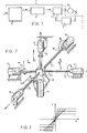
- An industrial robot designated as a whole in figure 1 by reference numeral 1, comprise a control-computer 2, an arm or manipulator 3 coupled herewith, a wrist-joint 4 coupled with the manipulator 3 and a control-unit 5 coupled with the wrist-joint 4.
- the direction of the information signals exchanged between the various parts is indicated by arrows.
- the process is symbolically represented as a unit 6 coupled on the one hand with the wrist-joint 4 and with the control-unit 5 on the other.
- the term “the process” is to be understood to mean, for example, the insertion of a pin into a .hole.
- the wrist-joint 4 comprises a force measuring member (not shown).
- control-unit 5 connected as a feedback element is capable of influencing the driving force and the displacements in accordance with the forces occurring in the process, so that a dynamic process control is obtained.
- the properties, particularly, of the control-unit 5 will be described in detail hereinafter.
- Figure 2 shows an automatically operating, self-correcting robot wrist in accordance with the invention.
- a first object or pin 7 is rigidly clamped in an auxiliary body or claw 8 shown schematically.
- This claw 8 is journalled with the aid of known means (not shown) in a manner such that it has five degrees of freedom i.e. a translation in the directions indicated by x, y, and z and a rotation around the x and the y directions, indicated in the figure by Vx and v " respectively.
- the claw 8 can be driven by a motor i.e. for the degrees of freedom x, y, z, Vx and vy by the motors 9, 10; 11, 12, and 13 respectively.
- the motors 9, 10, 11 act upon the claw 8 through the translation driving shafts 14, 15 and 16 respectively.
- the motors 12, 13 act upon the claw 8 through the rotation driving shafts 17 and 18 respectively.
- the rotation forces of the motors 12, 13 are transferred to the claw 8 through two rotary shafts 22, 23 connected with the claw 8 in the x and y directions.
- a known servo- system in which the servo-loop balances out the driving forces and the counter-forces is not capable of solving such a situation, since in the case of jamming there is no univocal relation between the measured force and the character of the relative positioning error.
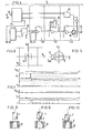
- Figure 3 is a graph of the functional relationship between the displacement u of the auxiliary body and the corresponding counter-force F.
- the compliance C is generally defined as being the quotient of the deflection and the force i.e. in figure 3 the cotangent of the angle between the line of connection between a point of the graph and the origin 0 and the positive u-axis.
- the force production level or else the maximum value of the driving force generating the counter-force is adjustable preferably in 16 steps, in the example shown, however, only three steps. These steps correspond to three horizontal parts of the graph on both sides of the origin 0.
- Figure 4 shows a basic diagram, partly in the form of blocks, of a control-unit 5 as shown in figure 1, by which during the process the corrective forces and displacements required in accordance with the invention are controlled for the claw 8.
- the control-unit 5 shown comprises a computer 26, an error buffer 27, a digital/analogue converter 28, a PID circuit 29, a controllable amplification control-circuit 30, a controllable circuit 31 for controlling the saturation level, a connecting terminal 32 for receiving the output signal of a position measuring member measuring the position of the first object 7 with respect to the second object 39, a connecting terminal 33 for receiving the output signal of a tachometer for stabilizing the servo loop in a known way and an output terminal 34 for the application of the output signal of the control-unit 5 to the driving motor concerned.
- the circuit 30 comprises a multiplexing circuit 35. By varying the gain factor of circuit 30 the compliance between the first object and the second object for the respective degree of freedom can be chosen.
- the circuit 31 includes a digital/analogue converter 40 and a diode bridge 36. As further active elements operational amplifiers (not shown) are provided.
- the input 50 receives the force measuring signal for controlling the computer.
- the control unit 5 is capable of performing the compliance variations described with reference to figure 5 and furthermore of controlling process-governing steps to be described hereinafter.
- the first phase in the establishment of a pin-hole connection is the initial approach phase.
- Figures 8, 9 and 10 illustrate at consecutive instants the respective approaches of pin 7 to a hole in a second object 39.
- the compliance values in the different degrees of freedom are programmed at normal values.
- the shape of the pin 7 and of the hole is such that no or hardly any self-finding effect is obtained. Therefore, when the pin fits very intimately in the hole, the chance of a correct relative insertion position is practically nil. Therefore, when the hole is approached the device according to the invention can bring the longitudinal direction of the pin at an angle p to the desired direction of displacement, i.e. the longitudinal direction of the hole.
- the wall of the hole and the pin have in common two contact points, at least two small contact surfaces, which corresponds in the case of given driving forces in accordance with the various degrees of freedom to the force F totel having a component F' x in the x-direction and a component F'y in the y-direction.
- the forces F' and F l y correspond to the counter-force in accordance with the degrees of freedom x and y respectively.
- the adjustability during operation of the functional relationship between the displacement of the auxiliary body in one of the degrees of freedom and the corresponding counter-force is employed during the assembling of objects in order to obtain a unique relation between the measured force and the relative positioningserror.
- said functional relationship is adjusted such that, upon a transgression in one or more of the degrees of freedom by the counter-forces of adjusted force values, the exertion of a counter-force in one or more of the degrees of freedom causes an elimination of the forcespattern concerned or a change of forces, that delivers a unique answer about the character of the relative positioningserror and about the displacement force concerned to be exerted.
- Figure 6 illustrates an orthogonal force space in which the abscissa corresponds to the force F in the x-direction and the ordinate to the force F in the y-direction. Consequently the forces F' X and F' y of Fig. 5 are the forces F. and Fy corresponding to one specific case.
- the force space of figure 6 shows two force zones i.e. a first, square zone 37 symmetrical around the origin 0 and a second zone 38 symmetrical around the origin in a square outer circumference, said second zone joining the first zone round about.
- the circumferential lines of the zones 37 and 38 correspond each to a given, adjusted maximum force. From the square circumferential shape of the zones it is evident that the same values are adjusted for the x- and the y-directions. In view of the symmetry of the situation illustrated in figure 5 this is a logical choice. For other situations other levels may be adjusted, which may be different for different degrees of freedom.
- the magnitude of the force at which the direction of the displacement reverses is adjustable.
- a variation of one or more force levels brings about a corresponding shift of two parallel, corresponding circumferential lines of figure 6, which is equivalent to a change-over of one set of horizontal, relatively parallel graph parts of figure 3 to a different set.
- Figure 7 shows as a function of time on the same time scale one below the other the moment Mv, for rotation about the x-axis, the force F x in the x-direction, the force Fy in the y-direction, the moment Mvy for rotation around the y-axis, the force F in the z-direction and the displacement commands c.
- the figure relates to a device having five degrees of freedom as shown in figure 2. A detailed analysis of the course of the relationship between the various forces will not be described. Some particularities are discussed below in order to illustrate the need for adaptable compliance.
- optimal compliance values should allow for angular movements of the pin initiated by small contact forces. Therefore, the rotational compliances are given high values and the saturation levels low values. The lateral compliances and saturation levels are programmed to normal values.
- the driving means for each degree of freedom may be formed by an electric motor.
- the force measuring member may then be designed for measuring the strength of the motor current.
- the electric motor may be a direct-current motor and the force measuring member may be a resistor connected in series with the motor, the voltage across it being unambiguously connected with the driving force provided by the motor and producing the counter-force, so that the voltage across said resistor can be used as a control- signal.
- the invention is of importance for assembling processes but it is not limited thereto.
- a first object follows a second object with a predetermined, constant force.
- Examples of use thereof are arc-welding with the use of a distance-determining expedient, automated, mechanical measuring instruments, cementing contact edges, for example, of incandescent lamps, television tubes and the like with the aid of a cement spray nozzle and a distance-determining expedient.
- the device according to the invention permits of carrying out mass production assembly, in which an excellent uniformity of the products is attended by a short time of manufacture. Moreover, the risk of waste of faulty products and of non-productive periods of the robot is minimized.
Landscapes
- Engineering & Computer Science (AREA)
- Mechanical Engineering (AREA)
- Robotics (AREA)
- Manipulator (AREA)
- Automatic Assembly (AREA)
- Control Of Position Or Direction (AREA)
- Valve Device For Special Equipments (AREA)
- Paper (AREA)
- Buildings Adapted To Withstand Abnormal External Influences (AREA)
Claims (6)
Priority Applications (1)
| Application Number | Priority Date | Filing Date | Title |
|---|---|---|---|
| AT80200179T ATE4094T1 (de) | 1979-03-12 | 1980-02-28 | Verschiebe-steuervorrichtung. |
Applications Claiming Priority (2)
| Application Number | Priority Date | Filing Date | Title |
|---|---|---|---|
| NL7901956 | 1979-03-12 | ||
| NL7901956A NL7901956A (nl) | 1979-03-12 | 1979-03-12 | Verplaatsingsbesturingsinrichting. |
Publications (2)
| Publication Number | Publication Date |
|---|---|
| EP0015618A1 EP0015618A1 (de) | 1980-09-17 |
| EP0015618B1 true EP0015618B1 (de) | 1983-07-13 |
Family
ID=19832789
Family Applications (1)
| Application Number | Title | Priority Date | Filing Date |
|---|---|---|---|
| EP80200179A Expired EP0015618B1 (de) | 1979-03-12 | 1980-02-28 | Verschiebe-Steuervorrichtung |
Country Status (6)
| Country | Link |
|---|---|
| US (1) | US4445273A (de) |
| EP (1) | EP0015618B1 (de) |
| JP (1) | JPS55129809A (de) |
| AT (1) | ATE4094T1 (de) |
| DE (1) | DE3064078D1 (de) |
| NL (1) | NL7901956A (de) |
Families Citing this family (25)
| Publication number | Priority date | Publication date | Assignee | Title |
|---|---|---|---|---|
| JPS5843238B2 (ja) * | 1980-12-30 | 1983-09-26 | ファナック株式会社 | ロボット制御方式 |
| US4409736A (en) * | 1981-07-31 | 1983-10-18 | The Charles Stark Draper Laboratory, Inc. | Null seeking system for remote center compliance device |
| GB2125768B (en) * | 1982-03-15 | 1986-04-16 | Pavel Jan Drazon | A manipulating unit |
| CA1237739A (en) * | 1982-09-21 | 1988-06-07 | Kazuo Asakawa | Supporting device |
| FR2537907B1 (fr) * | 1982-12-17 | 1985-09-20 | Du Pin Cellulose | Dispositif automatique pour traiter un produit |
| US4595334A (en) * | 1984-01-18 | 1986-06-17 | International Business Machines Corporation | Robotic apparatus with improved positioning accuracy |
| US4642438A (en) * | 1984-11-19 | 1987-02-10 | International Business Machines Corporation | Workpiece mounting and clamping system having submicron positioning repeatability |
| GB2168029B (en) * | 1984-12-04 | 1988-02-17 | Nat Res Dev | Alignment devices |
| US4842475A (en) * | 1984-12-27 | 1989-06-27 | Board Of Governors For Higher Education, State Of Rhode Island | Computer controlled adaptive compliance assembly workstation |
| GB8501654D0 (en) * | 1985-01-23 | 1985-02-27 | Emi Ltd | Compliant coupling mechanism |
| US4891764A (en) * | 1985-12-06 | 1990-01-02 | Tensor Development Inc. | Program controlled force measurement and control system |
| US4756662A (en) * | 1986-03-31 | 1988-07-12 | Agency Of Industrial Science & Technology | Varible compliance manipulator |
| US4804896A (en) * | 1987-09-30 | 1989-02-14 | University Of Lowell | Vibratory interference sensor |
| US4808063A (en) * | 1987-11-03 | 1989-02-28 | Westinghouse Electric Corp. | Robot system employing force/position control |
| FR2644379B1 (fr) * | 1989-01-27 | 1994-07-08 | Ricard Claude | Procedes et dispositifs pour inserer automatiquement une piece male dans une piece femelle |
| US5305521A (en) * | 1991-06-25 | 1994-04-26 | Canon Kabushiki Kaisha | Ink-jet head assembling method |
| GB9215265D0 (en) * | 1992-07-17 | 1992-09-02 | Ariel Ind Plc | Improved mechanism for positioning portable fastener applicators |
| US5577902A (en) * | 1994-05-16 | 1996-11-26 | Director-General Of Agency Of Industrial Science And Technology | Robot hand for forging working |
| JP2000296485A (ja) * | 1999-04-15 | 2000-10-24 | Minolta Co Ltd | マイクロマニピュレータ |
| US6691392B2 (en) * | 2001-05-16 | 2004-02-17 | Utica Enterprises, Inc. | Method and apparatus for assembling exterior automotive vehicle body components onto an automotive vehicle body |
| FR2835579B1 (fr) * | 2002-02-04 | 2004-05-21 | Commissariat Energie Atomique | Dispositif de deplacement spherique d'element |
| US20050110447A1 (en) * | 2002-03-21 | 2005-05-26 | Ulrich Weber | Device for manipulating the angular position of an object relative to a fixed structure |
| DE10212547A1 (de) * | 2002-03-21 | 2003-10-02 | Zeiss Carl Smt Ag | Vorrichtung zur Manipulation der Winkellage eines Gegenstands gegenüber einer festen Struktur |
| CN106624726B (zh) * | 2016-12-19 | 2019-10-08 | 深圳市联合东创科技有限公司 | 机械对位组装装置及其对位组装方法 |
| US11318611B2 (en) | 2020-04-14 | 2022-05-03 | Fanuc Corporation | Multi center impedance control |
Family Cites Families (6)
| Publication number | Priority date | Publication date | Assignee | Title |
|---|---|---|---|---|
| US3246223A (en) * | 1962-05-03 | 1966-04-12 | American Mach & Foundry | Selective condition limiting recording system for a motor controlled machine tool |
| US3824674A (en) * | 1972-07-19 | 1974-07-23 | Hitachi Ltd | Automatic assembly control method and device therefor |
| DE2358498C2 (de) * | 1972-12-01 | 1984-07-05 | Hitachi, Ltd., Tokio/Tokyo | Vorrichtung zum automatischen Einsetzen eines ersten Teils in eine Öffnung eines zweiten Teils |
| US3965562A (en) * | 1974-01-18 | 1976-06-29 | Hitachi, Ltd. | Method and apparatus for positioning control |
| DE2504127A1 (de) * | 1974-02-01 | 1975-09-04 | Hitachi Ltd | Geraet fuer automatische montage |
| JPS5435355B2 (de) * | 1974-12-04 | 1979-11-01 |
-
1979
- 1979-03-12 NL NL7901956A patent/NL7901956A/nl not_active Application Discontinuation
-
1980
- 1980-02-28 EP EP80200179A patent/EP0015618B1/de not_active Expired
- 1980-02-28 DE DE8080200179T patent/DE3064078D1/de not_active Expired
- 1980-02-28 AT AT80200179T patent/ATE4094T1/de active
- 1980-03-11 JP JP3146680A patent/JPS55129809A/ja active Pending
-
1981
- 1981-11-30 US US06/325,835 patent/US4445273A/en not_active Expired - Fee Related
Also Published As
| Publication number | Publication date |
|---|---|
| NL7901956A (nl) | 1980-09-16 |
| US4445273A (en) | 1984-05-01 |
| EP0015618A1 (de) | 1980-09-17 |
| DE3064078D1 (en) | 1983-08-18 |
| JPS55129809A (en) | 1980-10-08 |
| ATE4094T1 (de) | 1983-07-15 |
Similar Documents
| Publication | Publication Date | Title |
|---|---|---|
| EP0015618B1 (de) | Verschiebe-Steuervorrichtung | |
| DE3810691C2 (de) | ||
| EP3957436B1 (de) | Bearbeitungskopf mit aktiver korrektur, verfahren zum betrieb des kopfes und verwendung desselben | |
| US6378190B2 (en) | Method for stress-free assembly of components | |
| US6216056B1 (en) | Method of controlling force assisting device and control apparatus using the same | |
| CN110449882B (zh) | 结合力控的搜索装配方法 | |
| EP0149682B1 (de) | Verfahren zur bestimmung der referenzortung eines industriellen roboters | |
| JP2013006231A (ja) | 自動組立装置および自動組立装置による部品組立方法 | |
| DE19849720A1 (de) | Verfahren und Greifersystem zur Durchführung des Verfahrens zur präzisen Handhabung und Montage von kleinen Bauteilen | |
| Taylor et al. | Precise manipulation with endpoint sensing | |
| JP2768210B2 (ja) | ワークの嵌合方法及び嵌合装置 | |
| US4842475A (en) | Computer controlled adaptive compliance assembly workstation | |
| JP3577124B2 (ja) | 力制御ロボットを用いて嵌合データを取得する方法 | |
| CN120941048A (zh) | 一种用于磁块磁极夹持结构的智能装配设备及其控制方法 | |
| Hopkins et al. | Force sensing as an aid to assembly | |
| Everett et al. | A sensor used for measurements in the calibration of production robots | |
| Qiao et al. | Precise robotic chamferless peg-hole insertion operation without force feedback and remote centre compliance (RCC) | |
| CN115876137B (zh) | 一种随位并联三坐标定位器组的手动联控调姿定位方法 | |
| JPH0732147A (ja) | ロボットのウィービング制御パラメータ計測装置 | |
| JPS6311289A (ja) | ロボツトの基準姿勢デ−タ読込方式 | |
| JP2734868B2 (ja) | 多軸ロボットの位置精度点検装置 | |
| WO1995007793A2 (en) | Force and position controlled manipulator | |
| Ferreira et al. | Automation of a teleoperated microassembly desktop station supervised by virtual reality | |
| CN120846195A (zh) | 机器人灵活检测方法、装置及生产线改良方法、生产线 | |
| Liu et al. | An Experiment Study and Analysis of Delta Robot Accuracy and Stability Improvement with Impact Testing |
Legal Events
| Date | Code | Title | Description |
|---|---|---|---|
| PUAI | Public reference made under article 153(3) epc to a published international application that has entered the european phase |
Free format text: ORIGINAL CODE: 0009012 |
|
| AK | Designated contracting states |
Designated state(s): AT BE CH DE FR GB IT LU NL SE |
|
| 17P | Request for examination filed | ||
| ITF | It: translation for a ep patent filed | ||
| GRAA | (expected) grant |
Free format text: ORIGINAL CODE: 0009210 |
|
| AK | Designated contracting states |
Designated state(s): AT BE CH DE FR GB IT LU NL SE |
|
| REF | Corresponds to: |
Ref document number: 4094 Country of ref document: AT Date of ref document: 19830715 Kind code of ref document: T |
|
| REF | Corresponds to: |
Ref document number: 3064078 Country of ref document: DE Date of ref document: 19830818 |
|
| ET | Fr: translation filed | ||
| PGFP | Annual fee paid to national office [announced via postgrant information from national office to epo] |
Ref country code: FR Payment date: 19840131 Year of fee payment: 5 |
|
| PGFP | Annual fee paid to national office [announced via postgrant information from national office to epo] |
Ref country code: CH Payment date: 19840227 Year of fee payment: 5 |
|
| PG25 | Lapsed in a contracting state [announced via postgrant information from national office to epo] |
Ref country code: LU Free format text: LAPSE BECAUSE OF NON-PAYMENT OF DUE FEES Effective date: 19840229 |
|
| PGFP | Annual fee paid to national office [announced via postgrant information from national office to epo] |
Ref country code: LU Payment date: 19840312 Year of fee payment: 5 |
|
| PGFP | Annual fee paid to national office [announced via postgrant information from national office to epo] |
Ref country code: SE Payment date: 19840331 Year of fee payment: 5 Ref country code: BE Payment date: 19840331 Year of fee payment: 5 |
|
| PLBE | No opposition filed within time limit |
Free format text: ORIGINAL CODE: 0009261 |
|
| STAA | Information on the status of an ep patent application or granted ep patent |
Free format text: STATUS: NO OPPOSITION FILED WITHIN TIME LIMIT |
|
| 26N | No opposition filed | ||
| PGFP | Annual fee paid to national office [announced via postgrant information from national office to epo] |
Ref country code: DE Payment date: 19850326 Year of fee payment: 6 |
|
| PGFP | Annual fee paid to national office [announced via postgrant information from national office to epo] |
Ref country code: AT Payment date: 19870202 Year of fee payment: 8 |
|
| PGFP | Annual fee paid to national office [announced via postgrant information from national office to epo] |
Ref country code: NL Payment date: 19870228 Year of fee payment: 8 |
|
| PG25 | Lapsed in a contracting state [announced via postgrant information from national office to epo] |
Ref country code: GB Effective date: 19890228 Ref country code: CH Effective date: 19890228 Ref country code: BE Effective date: 19890228 Ref country code: AT Effective date: 19890228 |
|
| PG25 | Lapsed in a contracting state [announced via postgrant information from national office to epo] |
Ref country code: SE Effective date: 19890301 |
|
| BERE | Be: lapsed |
Owner name: LEUVEN RESEARCH & DEVELOPMENT V.Z.W. Effective date: 19890228 |
|
| PG25 | Lapsed in a contracting state [announced via postgrant information from national office to epo] |
Ref country code: NL Effective date: 19890901 |
|
| NLV4 | Nl: lapsed or anulled due to non-payment of the annual fee | ||
| GBPC | Gb: european patent ceased through non-payment of renewal fee | ||
| PG25 | Lapsed in a contracting state [announced via postgrant information from national office to epo] |
Ref country code: FR Free format text: LAPSE BECAUSE OF NON-PAYMENT OF DUE FEES Effective date: 19891027 |
|
| REG | Reference to a national code |
Ref country code: CH Ref legal event code: PL |
|
| PG25 | Lapsed in a contracting state [announced via postgrant information from national office to epo] |
Ref country code: DE Effective date: 19891101 |
|
| REG | Reference to a national code |
Ref country code: FR Ref legal event code: ST |
|
| EUG | Se: european patent has lapsed |
Ref document number: 80200179.2 Effective date: 19900118 |