EP0015657A2 - Connecteur de fibre optique - Google Patents
Connecteur de fibre optique Download PDFInfo
- Publication number
- EP0015657A2 EP0015657A2 EP80300395A EP80300395A EP0015657A2 EP 0015657 A2 EP0015657 A2 EP 0015657A2 EP 80300395 A EP80300395 A EP 80300395A EP 80300395 A EP80300395 A EP 80300395A EP 0015657 A2 EP0015657 A2 EP 0015657A2
- Authority
- EP
- European Patent Office
- Prior art keywords
- optical fibre
- connector
- alignment
- body member
- optical
- Prior art date
- Legal status (The legal status is an assumption and is not a legal conclusion. Google has not performed a legal analysis and makes no representation as to the accuracy of the status listed.)
- Granted
Links
Images


Classifications
-
- G—PHYSICS
- G02—OPTICS
- G02B—OPTICAL ELEMENTS, SYSTEMS OR APPARATUS
- G02B6/00—Light guides; Structural details of arrangements comprising light guides and other optical elements, e.g. couplings
- G02B6/24—Coupling light guides
- G02B6/36—Mechanical coupling means
- G02B6/38—Mechanical coupling means having fibre to fibre mating means
- G02B6/3807—Dismountable connectors, i.e. comprising plugs
- G02B6/381—Dismountable connectors, i.e. comprising plugs of the ferrule type, e.g. fibre ends embedded in ferrules, connecting a pair of fibres
- G02B6/3826—Dismountable connectors, i.e. comprising plugs of the ferrule type, e.g. fibre ends embedded in ferrules, connecting a pair of fibres characterised by form or shape
- G02B6/383—Hermaphroditic connectors, i.e. two identical plugs mating with one another, each plug having both male and female diametrically opposed engaging parts
-
- G—PHYSICS
- G02—OPTICS
- G02B—OPTICAL ELEMENTS, SYSTEMS OR APPARATUS
- G02B6/00—Light guides; Structural details of arrangements comprising light guides and other optical elements, e.g. couplings
- G02B6/24—Coupling light guides
- G02B6/36—Mechanical coupling means
- G02B6/38—Mechanical coupling means having fibre to fibre mating means
- G02B6/3807—Dismountable connectors, i.e. comprising plugs
- G02B6/3833—Details of mounting fibres in ferrules; Assembly methods; Manufacture
- G02B6/3834—Means for centering or aligning the light guide within the ferrule
- G02B6/3838—Means for centering or aligning the light guide within the ferrule using grooves for light guides
-
- G—PHYSICS
- G02—OPTICS
- G02B—OPTICAL ELEMENTS, SYSTEMS OR APPARATUS
- G02B6/00—Light guides; Structural details of arrangements comprising light guides and other optical elements, e.g. couplings
- G02B6/24—Coupling light guides
- G02B6/36—Mechanical coupling means
- G02B6/38—Mechanical coupling means having fibre to fibre mating means
- G02B6/3807—Dismountable connectors, i.e. comprising plugs
- G02B6/3873—Connectors using guide surfaces for aligning ferrule ends, e.g. tubes, sleeves, V-grooves, rods, pins, balls
-
- G—PHYSICS
- G02—OPTICS
- G02B—OPTICAL ELEMENTS, SYSTEMS OR APPARATUS
- G02B6/00—Light guides; Structural details of arrangements comprising light guides and other optical elements, e.g. couplings
- G02B6/24—Coupling light guides
- G02B6/36—Mechanical coupling means
- G02B6/38—Mechanical coupling means having fibre to fibre mating means
- G02B6/3807—Dismountable connectors, i.e. comprising plugs
- G02B6/389—Dismountable connectors, i.e. comprising plugs characterised by the method of fastening connecting plugs and sockets, e.g. screw- or nut-lock, snap-in, bayonet type
Definitions
- the invention relates to an optical fibre connector of the kind in which an optical fibre is located in an interstitial space defined between a plurality of surfaces.
- Such connector is disclosed in United States Patent No. 4,087,155 in which the surfaces are defined by adjacent spheres. Two connectors are disposed mutually adjacent in a common sleeve in an attempt axially to align the optical fibres.
- the interstitial space is defined by first and second convergent alignment surfaces of a one-piece body member, the first alignment surface having an integral surface portion extending in rectilinear fashion in the longitudinal direction beyond the second alignment surface, the connector being matable with a further, similar, connector so that the extended surface portion of each body member engages an optical fibre received in the interstitial space of the other body member retaining the optical fibre against the first and second alignment surfaces of the other body member thereby precisely aligning the axes of the optical fibres.
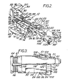
- Each connector comprises a body member 16, a clamping member 18, and a strain relief member 20, each member being moulded in one piece from suitable plastics material.
- Each body member 16 is subtantially rigid and comprises a base 22 having an upper surface 24 extending between a rear end 26 and a front end 28, and having opposite sides 3.2 and 59.
- a recess 30 is formed in the base opening to the upper surface and one side 32 intermediate the ends 26 and 28, and communicating with a socket forming passageway 58 ( Figure 9) extending transversely through the base and opening to the side 59.
- a longitudinally extending rib is formed on an upper wall of the passageway 58 and has a ramp-form locking shoulder 61 facing away from the recess 30.
- a locking recess 36 having a bevelled locking shoulder 34 is formed in a portion of the side 32 which portion is of reduced section and located forwardly of recess 30.
- a longitudinally extending alignment block 38 is formed on the base and has an upper alignment arm 40 projecting beyond the forward end 28.
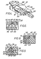
- a longitudinally extending inner side of the alignment block 38 is undercut to provide a flat first optical. fibre core supporting surface 42 defining, an acute angle with the upper surface 24 of the base, the latter surface providing a second optical fibre core supporting surface.
- the inner side is rebated adjacent the arm to provide an intermediate, diagonally recessed, portion 44 intersecting a rectilinear extension 46 of surface 42 which extends to a front end of alignment arm 40.
- the extension 46 of surface 42 and the adjacent portion of the upper surface 24, provide two optical fibre alignment surfaces.
- the alignment arm 40 has an inwardly facing, longitudinally extending, guide surface 48, a bevelled nose portion 50, an outwardly facing nose surface 51, and a camming surface 52 inclined at an obtuse angle to the plane of the surface 24.
- a locking shoulder 53 .and a locking recess 54 are formed in the alignment arm 40, at a location rearward of surface 52, and a locking recess 56 and locking shoulder 57 are formed in the base 22 transversely aligned with the locking detent 36.
- a lower alignment arm 60 extends forwardly from a lower side of the base 22 parallel with and spaced apart from the upper alignment arm 40 and has a chamfered nose 62.
- a channel 63 is formed between the side 32 of the base and a side of the root end of arm 60.
- each body member is formed with a fibre supporting portion 64 having a central neck 66'formed with an upper ridged surface 67 recessed below the plane of upper surface 24 a distance equal to the thickness of the optical fibre cladding.
- Each clamping member 18 comprises a body portion 68 having a cantilever spring arm 70 extending forwardly from-one side and formed with a latching projection 72 at its free end, which projection has an oppositely facing camming surface and latching shoulder 74 and 76, respectively.
- the opposite side of the clamping member 18 defines a longitudinally extending third optical fibre supporting surface 78 ( Figures 1 and 9).
- a cantilevered tab 80 extends laterally from the body portion 68 and is provided at its free end with a locking lip having an inwardly directed locking ramp 82.
- the strain relief member 20 comprises a generally U-shaped body having two spaced legs 84, 86, depending from opposite ends of a transverse portion 88, and having inwardly directed latching flanges 90, 92, at respective free ends.
- An inner surface 94 of the transverse portion 88 is formed with an optical fibre receiving groove 96.
- an optical fibre end positioning gauge 98 comprises a transverse portion 100 from opposite ends of which extend two parallel latching legs 102, 104 having latching projections 106, 108, respectively, at their free ends.
- the transverse portion 100 provides an inwardly facing, flat, reference surface 110.
- Serrations 112, 114 are formed on the root ends of the legs to facilitate manual handling.
- an optical fibre 116 having cladding 118 which has been removed to expose a precise length of fibre core comprising an anterior section 120, adjacent an optically polished face 122, and a posterior section 124, is located on the body with the posterior core section 124 abutting the first supporting surface 42 and the second supporting surface 24.
- the anterior core section is laterally supported by the rectilinear extension 46 of surface 42, and a forward portion of surface 24 while the cladded portions extends across surface 67.
- the gauge 98 is moved from the position of Figure 2 to the position of Figure 3, between alignment arms 40 and 60 with the leg members 102, 104 on opposite sides of the base 22 and projections 106, 108 snapping into the first and second recesses 36, 56 respectively, detachably to lock the gauge 98 and the base 22 together, with the reference surface 110 abutting the front end 28 of the base.
- a raised stop portion of the reference surface abuts the optical face of the fibre core to ensure that it is coplanar with end 28.
- the optical face of the fibre core may be located at a predetermined distance behind or in front of the end 28 to achieve optimum spacing between the optical faces when the connectors are mated.
- the clamping member 18 is mounted on the base 22 by inserting the tab 80 laterally into passageway 58 until the complementary ramp surfaces 61 and 82 are in locking engagement, the lateral movement causing the third optical fibre supporting surface 78 to wedge the posterior section 124 of the fibre core between the first waveguide supporting surface 42, and the second waveguide supporting surface 24, as shown in Figure 9.
- the complementary configurations of the ramp surfaces 61, 82 together with the resiliency of the tab 80 enable the passageway defined between the three supporting surfaces to be of varying cross-sectional size to accommodate optical fibres having a limited range.of diameters, or.to accommodate variations in the-diameter of a given optical fibre caused by manufacturing tolerances.
- the gauge 98 is removed from the body member 16 and the strain relief member 20 is snap-fitted on the rearward portion 64 of the body member 16 with the optical fibre pressed against the ridged surface 67 by the groove 96.
- two connectors are mated by moving them axially together to bring the camming surface 74 of one connector's clamping member into sliding engagement with the other connector's nose surface 51, together with sliding engagement of both connectors, guide surfaces 48.
- both connectors and optical fibres are slightly laterally misaligned.
- each optical fibre will be substantially enclosed by an oversize triangle of surfaces protecting the optical fibre during mating.
- the surface 42 of the connector 14 will be spaced from the optical fibre in the connector 12 for substantially the entire mating movement avoiding abrasion of the optical fibre.
- Such further movement together of the connectors causes resilient flexure of arms 70 bringing complementary camming surfaces 52 and 74 into engagement providing laterally inward and downward force components assisting in retaining the connectors in alignment.
- the lower alignment arms 60 are in mutual sliding engagement in channels 63 further assisting in retaining the connectors in correct alignment during mating.
- the projections 72 releasably latch in the recesses 54, as shown in Figure 6 and the ends 28 of the body member are retained abutting against each other by residual resiliency in the arms 70.
- each alignment surface 46 engages both fibre cores assisting in maintaining precise axial alignment of the cores while the connectors are clamped with any desired optimum spacing between optical faces 122 of the optical fibres using the gauge.
Landscapes
- Physics & Mathematics (AREA)
- General Physics & Mathematics (AREA)
- Optics & Photonics (AREA)
- Mechanical Coupling Of Light Guides (AREA)
Priority Applications (1)
| Application Number | Priority Date | Filing Date | Title |
|---|---|---|---|
| AT80300395T ATE7544T1 (de) | 1979-02-26 | 1980-02-12 | Verbinder fuer optische faser. |
Applications Claiming Priority (2)
| Application Number | Priority Date | Filing Date | Title |
|---|---|---|---|
| US06/015,265 US4245887A (en) | 1979-02-26 | 1979-02-26 | Optical waveguide connector |
| US15265 | 1979-02-26 |
Publications (3)
| Publication Number | Publication Date |
|---|---|
| EP0015657A2 true EP0015657A2 (fr) | 1980-09-17 |
| EP0015657A3 EP0015657A3 (en) | 1980-10-15 |
| EP0015657B1 EP0015657B1 (fr) | 1984-05-16 |
Family
ID=21770430
Family Applications (1)
| Application Number | Title | Priority Date | Filing Date |
|---|---|---|---|
| EP80300395A Expired EP0015657B1 (fr) | 1979-02-26 | 1980-02-12 | Connecteur de fibre optique |
Country Status (11)
| Country | Link |
|---|---|
| US (1) | US4245887A (fr) |
| EP (1) | EP0015657B1 (fr) |
| JP (1) | JPS55117115A (fr) |
| AR (1) | AR220817A1 (fr) |
| AT (1) | ATE7544T1 (fr) |
| AU (1) | AU5541580A (fr) |
| BR (1) | BR8000944A (fr) |
| CA (1) | CA1116904A (fr) |
| DE (1) | DE3067801D1 (fr) |
| ES (1) | ES248852Y (fr) |
| MX (1) | MX146856A (fr) |
Cited By (3)
| Publication number | Priority date | Publication date | Assignee | Title |
|---|---|---|---|---|
| EP0171664A1 (fr) * | 1984-08-03 | 1986-02-19 | Licentia Patent-Verwaltungs-GmbH | Dispositif de couplage pour fibre optique |
| WO1997001784A1 (fr) * | 1995-06-29 | 1997-01-16 | Minnesota Mining And Manufacturing Company | Connecteur pour fibre nue |
| US5682450A (en) * | 1995-06-29 | 1997-10-28 | Minnesota Mining And Manufacturing Company | Fiber optic connector element |
Families Citing this family (11)
| Publication number | Priority date | Publication date | Assignee | Title |
|---|---|---|---|---|
| GB2039074B (en) * | 1978-12-16 | 1982-12-15 | Plessey Co Ltd | Optical fibre connectors |
| US4449784A (en) * | 1981-06-22 | 1984-05-22 | Trw Inc. | Hybrid optical/electrical connector |
| US4445750A (en) * | 1981-06-22 | 1984-05-01 | Trw Inc. | Articulating fiber optic connectors with resilient mounting block |
| US4461537A (en) * | 1981-12-24 | 1984-07-24 | Molex Incorporated | Fiber optic connector assembly |
| US4605281A (en) * | 1984-01-17 | 1986-08-12 | Hellewell Byron A | Self-aligning fiber optic connector |
| US5076656A (en) * | 1984-06-08 | 1991-12-31 | Briggs Robert C | High precision optical fiber connectors |
| US4712861A (en) * | 1985-02-07 | 1987-12-15 | Northern Telecom Limited | Two-channel hermaphroditic fiber connector |
| DE3729075A1 (de) * | 1987-09-01 | 1989-03-16 | Schmidt Feinmech | Steckverbindung fuer lichtleiter |
| US5966487A (en) * | 1997-05-27 | 1999-10-12 | Methode Electronics, Inc. | External pluggable high frequency data communication module |
| US6299362B1 (en) | 1998-04-22 | 2001-10-09 | Stratos Lightwave, Inc. | High speed optical interface converter module having mounting halves |
| DE202011003983U1 (de) * | 2011-03-15 | 2011-05-12 | Bürkert Werke GmbH | Lichtwellenleiterkupplung |
Family Cites Families (15)
| Publication number | Priority date | Publication date | Assignee | Title |
|---|---|---|---|---|
| DK143620A (fr) * | 1974-06-20 | |||
| US3885859A (en) * | 1974-06-24 | 1975-05-27 | Northern Electric Co | Optical fibre connectors |
| GB1454600A (en) * | 1974-11-08 | 1976-11-03 | Plessey Co Ltd | Optical fibre connector doll' |
| US4047796A (en) * | 1975-09-15 | 1977-09-13 | International Telephone And Telegraph Corporation | Precision optical fiber connector |
| US4019241A (en) * | 1975-11-10 | 1977-04-26 | Thomas & Betts Corporation | Method of splicing elongate members |
| US4056305A (en) * | 1976-04-26 | 1977-11-01 | International Telephone And Telegraph Corporation | Single optical fiber connector utilizing elastomeric alignment device |
| FR2367295A1 (fr) * | 1976-10-05 | 1978-05-05 | Cables De Lyon Geoffroy Delore | Procede et disposit |
| US4155624A (en) * | 1976-12-23 | 1979-05-22 | Thomas & Betts Corporation | Duplex optical fiber connector |
| US4094580A (en) * | 1976-12-27 | 1978-06-13 | Bell Telephone Laboratories, Incorporated | Hermaphrodite optical fiber connector |
| US4087155A (en) * | 1977-03-23 | 1978-05-02 | International Telephone & Telegraph Corporation | Single optical fiber connector utilizing spherical alignment elements |
| GB1576459A (en) * | 1977-04-28 | 1980-10-08 | Standard Telephones Cables Ltd | Optical fibres connectors |
| FR2390745A2 (fr) * | 1977-05-13 | 1978-12-08 | Socapex | Connecteur pour monofibre optique |
| JPS545746A (en) * | 1977-06-15 | 1979-01-17 | Mitsubishi Electric Corp | Optical fiber connector |
| JPS5421356A (en) * | 1977-07-18 | 1979-02-17 | Mitsubishi Electric Corp | Optical fiber connector |
| US4162821A (en) * | 1977-12-20 | 1979-07-31 | Amp Incorporated | Means for in-line connection of optical fiber pairs |
-
1979
- 1979-02-26 US US06/015,265 patent/US4245887A/en not_active Expired - Lifetime
-
1980
- 1980-02-11 AU AU55415/80A patent/AU5541580A/en not_active Abandoned
- 1980-02-12 DE DE8080300395T patent/DE3067801D1/de not_active Expired
- 1980-02-12 AT AT80300395T patent/ATE7544T1/de not_active IP Right Cessation
- 1980-02-12 EP EP80300395A patent/EP0015657B1/fr not_active Expired
- 1980-02-14 BR BR8000944A patent/BR8000944A/pt unknown
- 1980-02-21 CA CA000346201A patent/CA1116904A/fr not_active Expired
- 1980-02-22 JP JP2066680A patent/JPS55117115A/ja active Pending
- 1980-02-25 AR AR280077A patent/AR220817A1/es active
- 1980-02-25 MX MX181311A patent/MX146856A/es unknown
- 1980-02-25 ES ES1980248852U patent/ES248852Y/es not_active Expired
Cited By (4)
| Publication number | Priority date | Publication date | Assignee | Title |
|---|---|---|---|---|
| EP0171664A1 (fr) * | 1984-08-03 | 1986-02-19 | Licentia Patent-Verwaltungs-GmbH | Dispositif de couplage pour fibre optique |
| WO1997001784A1 (fr) * | 1995-06-29 | 1997-01-16 | Minnesota Mining And Manufacturing Company | Connecteur pour fibre nue |
| US5682450A (en) * | 1995-06-29 | 1997-10-28 | Minnesota Mining And Manufacturing Company | Fiber optic connector element |
| US5732174A (en) * | 1995-06-29 | 1998-03-24 | Minnesota Mining And Manufacturing Company | Bare fiber connector |
Also Published As
| Publication number | Publication date |
|---|---|
| AU5541580A (en) | 1980-09-04 |
| US4245887A (en) | 1981-01-20 |
| EP0015657B1 (fr) | 1984-05-16 |
| MX146856A (es) | 1982-08-25 |
| BR8000944A (pt) | 1980-10-29 |
| EP0015657A3 (en) | 1980-10-15 |
| JPS55117115A (en) | 1980-09-09 |
| ES248852U (es) | 1980-06-01 |
| DE3067801D1 (en) | 1984-06-20 |
| AR220817A1 (es) | 1980-11-28 |
| ES248852Y (es) | 1980-12-01 |
| CA1116904A (fr) | 1982-01-26 |
| ATE7544T1 (de) | 1984-06-15 |
Similar Documents
| Publication | Publication Date | Title |
|---|---|---|
| US11914195B2 (en) | Fiber optic ferrule and fiber optic ferrule receiver | |
| US5230032A (en) | Abutting tips fiber optic connector and method of making same | |
| US5335301A (en) | Fiber optic connector with sliding key | |
| EP0650602B1 (fr) | Ensemble de connexion pour fibre optique | |
| EP0002565B1 (fr) | Connecteur pour fibres optiques | |
| EP0015657A2 (fr) | Connecteur de fibre optique | |
| EP1148366B1 (fr) | Connecteur à fibre optique avec ajustement d'excentricité | |
| US6019521A (en) | Optical fiber connector | |
| EP0655807A2 (fr) | Dispositif pour assurer la position du connecteur | |
| EP3330757B1 (fr) | Connecteur de fibre optique pouvant commuter la polarité de connexion | |
| EP0015291B1 (fr) | Piece de raccordement pour fibres optiques | |
| EP4314918B1 (fr) | Support de ferrule pour ferrule mt miniature et interface d'adaptateur pour accouplement avec des connecteurs de fibre optique | |
| EP1329992B1 (fr) | Clip pour un connecteur monté de façon mobile | |
| US12321017B2 (en) | Fiber optic ferrule and fiber optic ferrule receiver | |
| US5091988A (en) | Article for connecting optical fibers | |
| CN108614328B (zh) | 可改变对接极性的光纤连接器 | |
| JP2625256B2 (ja) | 接触する先端部を有する光ファイバコネクタ | |
| JPS61226714A (ja) | 光コネクタ |
Legal Events
| Date | Code | Title | Description |
|---|---|---|---|
| PUAI | Public reference made under article 153(3) epc to a published international application that has entered the european phase |
Free format text: ORIGINAL CODE: 0009012 |
|
| PUAL | Search report despatched |
Free format text: ORIGINAL CODE: 0009013 |
|
| AK | Designated contracting states |
Designated state(s): AT BE CH DE FR GB IT NL SE |
|
| AK | Designated contracting states |
Designated state(s): AT BE CH DE FR GB IT NL SE |
|
| 17P | Request for examination filed |
Effective date: 19801117 |
|
| ITF | It: translation for a ep patent filed | ||
| GRAA | (expected) grant |
Free format text: ORIGINAL CODE: 0009210 |
|
| AK | Designated contracting states |
Designated state(s): AT BE CH DE FR GB IT NL SE |
|
| REF | Corresponds to: |
Ref document number: 7544 Country of ref document: AT Date of ref document: 19840615 Kind code of ref document: T |
|
| REF | Corresponds to: |
Ref document number: 3067801 Country of ref document: DE Date of ref document: 19840620 |
|
| ET | Fr: translation filed | ||
| PLBE | No opposition filed within time limit |
Free format text: ORIGINAL CODE: 0009261 |
|
| STAA | Information on the status of an ep patent application or granted ep patent |
Free format text: STATUS: NO OPPOSITION FILED WITHIN TIME LIMIT |
|
| 26N | No opposition filed | ||
| PGFP | Annual fee paid to national office [announced via postgrant information from national office to epo] |
Ref country code: FR Payment date: 19930109 Year of fee payment: 14 |
|
| PGFP | Annual fee paid to national office [announced via postgrant information from national office to epo] |
Ref country code: AT Payment date: 19930114 Year of fee payment: 14 |
|
| PGFP | Annual fee paid to national office [announced via postgrant information from national office to epo] |
Ref country code: GB Payment date: 19930119 Year of fee payment: 14 |
|
| PGFP | Annual fee paid to national office [announced via postgrant information from national office to epo] |
Ref country code: SE Payment date: 19930120 Year of fee payment: 14 |
|
| PGFP | Annual fee paid to national office [announced via postgrant information from national office to epo] |
Ref country code: BE Payment date: 19930126 Year of fee payment: 14 |
|
| PGFP | Annual fee paid to national office [announced via postgrant information from national office to epo] |
Ref country code: CH Payment date: 19930205 Year of fee payment: 14 |
|
| ITTA | It: last paid annual fee | ||
| PGFP | Annual fee paid to national office [announced via postgrant information from national office to epo] |
Ref country code: NL Payment date: 19930228 Year of fee payment: 14 |
|
| PG25 | Lapsed in a contracting state [announced via postgrant information from national office to epo] |
Ref country code: GB Effective date: 19940212 Ref country code: AT Effective date: 19940212 |
|
| PG25 | Lapsed in a contracting state [announced via postgrant information from national office to epo] |
Ref country code: SE Effective date: 19940213 |
|
| PG25 | Lapsed in a contracting state [announced via postgrant information from national office to epo] |
Ref country code: CH Effective date: 19940228 Ref country code: BE Effective date: 19940228 |
|
| REG | Reference to a national code |
Ref country code: GB Ref legal event code: 732E |
|
| BERE | Be: lapsed |
Owner name: AMP INC. (UNE SOC. DE PENNSYLVANIE) Effective date: 19940228 |
|
| PG25 | Lapsed in a contracting state [announced via postgrant information from national office to epo] |
Ref country code: NL Effective date: 19940901 |
|
| GBPC | Gb: european patent ceased through non-payment of renewal fee |
Effective date: 19940212 |
|
| NLV4 | Nl: lapsed or anulled due to non-payment of the annual fee | ||
| PG25 | Lapsed in a contracting state [announced via postgrant information from national office to epo] |
Ref country code: FR Effective date: 19941031 |
|
| REG | Reference to a national code |
Ref country code: CH Ref legal event code: PL |
|
| REG | Reference to a national code |
Ref country code: FR Ref legal event code: ST |
|
| EUG | Se: european patent has lapsed |
Ref document number: 80300395.3 Effective date: 19940910 |
|
| PGFP | Annual fee paid to national office [announced via postgrant information from national office to epo] |
Ref country code: DE Payment date: 19960227 Year of fee payment: 17 |
|
| PG25 | Lapsed in a contracting state [announced via postgrant information from national office to epo] |
Ref country code: DE Effective date: 19971101 |