EP0015708B1 - Dispositif de retenue pour occupants de véhicule - Google Patents
Dispositif de retenue pour occupants de véhicule Download PDFInfo
- Publication number
- EP0015708B1 EP0015708B1 EP80300573A EP80300573A EP0015708B1 EP 0015708 B1 EP0015708 B1 EP 0015708B1 EP 80300573 A EP80300573 A EP 80300573A EP 80300573 A EP80300573 A EP 80300573A EP 0015708 B1 EP0015708 B1 EP 0015708B1
- Authority
- EP
- European Patent Office
- Prior art keywords
- lap
- restraint means
- chest
- restraint
- occupant
- Prior art date
- Legal status (The legal status is an assumption and is not a legal conclusion. Google has not performed a legal analysis and makes no representation as to the accuracy of the status listed.)
- Expired
Links
- 230000000452 restraining effect Effects 0.000 title claims description 4
- 230000008878 coupling Effects 0.000 claims description 17
- 238000010168 coupling process Methods 0.000 claims description 17
- 238000005859 coupling reaction Methods 0.000 claims description 17
- 230000007423 decrease Effects 0.000 claims description 2
- 230000002301 combined effect Effects 0.000 description 1
- 230000000694 effects Effects 0.000 description 1
Images



Classifications
-
- B—PERFORMING OPERATIONS; TRANSPORTING
- B60—VEHICLES IN GENERAL
- B60R—VEHICLES, VEHICLE FITTINGS, OR VEHICLE PARTS, NOT OTHERWISE PROVIDED FOR
- B60R21/00—Arrangements or fittings on vehicles for protecting or preventing injuries to occupants or pedestrians in case of accidents or other traffic risks
- B60R21/02—Occupant safety arrangements or fittings, e.g. crash pads
-
- B—PERFORMING OPERATIONS; TRANSPORTING
- B60—VEHICLES IN GENERAL
- B60R—VEHICLES, VEHICLE FITTINGS, OR VEHICLE PARTS, NOT OTHERWISE PROVIDED FOR
- B60R22/00—Safety belts or body harnesses in vehicles
- B60R22/02—Semi-passive restraint systems, e.g. systems applied or removed automatically but not both ; Manual restraint systems
- B60R22/023—Three-point seat belt systems comprising two side lower and one side upper anchoring devices
-
- B—PERFORMING OPERATIONS; TRANSPORTING
- B60—VEHICLES IN GENERAL
- B60R—VEHICLES, VEHICLE FITTINGS, OR VEHICLE PARTS, NOT OTHERWISE PROVIDED FOR
- B60R22/00—Safety belts or body harnesses in vehicles
- B60R22/34—Belt retractors, e.g. reels
-
- B—PERFORMING OPERATIONS; TRANSPORTING
- B60—VEHICLES IN GENERAL
- B60R—VEHICLES, VEHICLE FITTINGS, OR VEHICLE PARTS, NOT OTHERWISE PROVIDED FOR
- B60R21/00—Arrangements or fittings on vehicles for protecting or preventing injuries to occupants or pedestrians in case of accidents or other traffic risks
- B60R21/02—Occupant safety arrangements or fittings, e.g. crash pads
- B60R2021/0206—Self-supporting restraint systems, e.g. restraining arms, plates or the like
- B60R2021/0213—Self-supporting restraint systems, e.g. restraining arms, plates or the like mounted on floor
-
- Y—GENERAL TAGGING OF NEW TECHNOLOGICAL DEVELOPMENTS; GENERAL TAGGING OF CROSS-SECTIONAL TECHNOLOGIES SPANNING OVER SEVERAL SECTIONS OF THE IPC; TECHNICAL SUBJECTS COVERED BY FORMER USPC CROSS-REFERENCE ART COLLECTIONS [XRACs] AND DIGESTS
- Y10—TECHNICAL SUBJECTS COVERED BY FORMER USPC
- Y10T—TECHNICAL SUBJECTS COVERED BY FORMER US CLASSIFICATION
- Y10T74/00—Machine element or mechanism
- Y10T74/20—Control lever and linkage systems
- Y10T74/20576—Elements
- Y10T74/20582—Levers
- Y10T74/206—Adjustable
Definitions
- This invention relates to systems for restraining forward movement, relative to a motor vehicle, of an occupant of the vehicle during sudden deceleration thereof.
- safety belts fitted with inertia reels are used to permit a vehicle occupant to lean forward, while wearing a safety belt, when the vehicle is travelling normally, but to restrain such forward movement when the vehicle is subject to sudden deceleration.
- the present invention is concerned with the provision of a safety system which provides this-facility without using an inertia locking mechanism.
- the present invention comprises apparatus of the foregoing kind in which the coupling means includes variable velocity ratio means arranged to vary the velocity ratio such that it increases to a maximum value and then decreases as the lap restraint means is moved forward by forward movement of the lap of the occupant.
- the coupling means includes variable velocity ratio means arranged to vary the velocity ratio such that it increases to a maximum value and then decreases as the lap restraint means is moved forward by forward movement of the lap of the occupant.
- the coupling means includes a first lever connected to the chest restraint means and mounted for angular movement about a first axis and a second lever connected to the lap restraint means and mounted for angular movement about a second axis disposed parallel to but forwardly of the first axis
- the variable velocity ratio means comprises a roller arranged to engage between respective mutually confronting surfaces of the two levers and to be displaceable from a first position to a second position nearer to the second axis and further from the first axis than the first position. It is necessary to provide means for releasing the coupling means, for example by disconnecting one of the levers from its corresponding restraint means, to enable the occupant to enter and leave his seat.
- the lap and chest restraint means comprise the lap and shoulder elements of a three-point safety belt and the coupling means comprises a reel on which the shoulder element is wound, rotation of the reel in the unwinding direction being opposed by tension in the lap element.
- the variable velocity ratio means may comprise means for varying the radius at which the force exerted by such tension is applied to the reel.
- variable velocity ratio means may be so arranged as to be capable of reducing the velocity ratio of the coupling means to zero so that forward movement of the chest restraint means can take place without any movement of the lap restraint means.
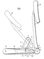
- the restraint system shown in Figures 1 and 2 comprises a cranked lap restraint arm 10, having a padded portion 12, to engage with the lap of a user, shown in outline at 14, and a chest restraint arm 16, the other end of which carries a pad 18 to engage with the chest of the user 14.
- the arm 16 is pivotally mounted on a shaft 20 located adjacent to the bottom of the back of the user's seat 22 ( Figure 1) while the arm 10 is mounted on a second shaft 24 adjacent to the front of the seat 22.
- the shafts 20 and 24 form part of the structure of the seat 22. It is, in any case, necessary for the shafts 20 and 24 to move with the seat 22 as its position is adjusted.
- a lever 26 is mounted on the shaft 20, fast with the arm 16.
- a second lever 28 is mounted on the shaft 24, and is detachably coupled to the arm 10 by a releasable latch 30 (not shown in detail).
- a roller 32 engages between confronting surfaces 34 and 36 formed on the levers 26 and 28 respectively.
- the roller 32 which can slide along the surfaces 34 and 36 between stops formed by abutments 38 and 40, is spring biased into engagement with the abutment 40 at the end nearer to the shaft 20.
- the roller 32 is weighted to increase its mass, thereby to increase the tendency for it to slide forwards into engagement with the other abutment during sudden deceleration of the vehicle into which it is fitted, as will be explained hereinafter.
- the latch 30 When the seat 22 is unoccupied, the latch 30 is released and the arms 10 and 16 are pushed as far forwards as the surrounding parts of the vehicle, for example the steering wheel, will. allow.
- the user 14 When the user 14 is seated, he pulls the arms 10 and 16 towards him so as to bring the pad 1 8 and the padded portion 12 of the arm 10 into engagement with his body.
- the latch 30 is then engaged, the arms 10 and 16 and levers 26 and 28 being in the positions shown in solid lines in Figure 2.
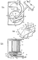
- Figures 4, 5 and 6 show a reel suitable for use as the coupling means of a restraint system where the chest and lap restraint means take the form of a three-point safety belt.
- the end of the shoulder element 40 of the belt, which forms the chest restraint means, is wound on to a reel 42, the wind-on direction being the clockwise direction as viewed in Figure 4.
- the reel 42 is mounted on a shaft 44 and is fast with a gear wheel 46 which meshes with a larger gear wheel 48 of e.g. four times the diameter of the wheel 46.
- the gear wheel 48 is mounted on a shaft 50 and is fast with a ratchet wheel 52.
- a two-armed lever 54 is also mounted on the shaft 50 by means of an elongate hole 56.
- One arm of the lever carries a protuberance 58 ( Figure 5) which serves as a pawl for engagement with the ratchet wheel 52, the elongate hole 56 allowing it to move into and out of engagement.
- the other arm of the lever 54 contains a slot 60 in which is slidably mounted a stud 62 connected to a stirrup 64 for attachment to the end of the lap element 66 of the safety belt.
- a hold-off plate 68 which is in light frictional engagement with the adjacent face of the ratchet wheel 52.
- the hold-off plate 68 carries a cam 70 which engages with a follower surface 72 projecting from the lever 54 so that, when the lever 54 and the hold-off plate 68 are in the relative positions shown in Figure 5, with the edge of the hold-off plate 68 abutting against the protuberance 58, the latter is held out of engagement with the ratchet wheel 52 but, when the lever 54 moves in the clockwise direction (as viewed in Figure 5) relative to the hold-off plate 68, the protuberance 58 is allowed to move into engagement with the ratchet wheel 52.
- a tension spring 74 connected to the stud 62 serves both to cause such clockwise movement and bias the stud 62 to the inner end of the slot 60.
- a stop 76 limits movement of the hold-off plate in the anti-clockwise direction.
- the shoulder element 40 When the belt is being put on, the shoulder element 40 is drawn off the reel 42 and initially, the lap element 66 is slack. Clockwise rotation of the reel 52, carrying the hold-off plate with it, causes the cam 70 thereof the lift the protuberance 58 on the lever 54 clear of the ratchet wheel 52. The reel 42 therefore remains free to rotate in both directions even if tension is subsequently applied to the lap element 66, for example just prior to engagement of the buckle (not shown). Inevitably, an excess length of the shoulder element 40 will be drawn off the reel and, as this is wound back, the hold-off plate 68 is carried in the anti-clockwise direction while the spring 74 holds the lever 54 stationary, freeing the protuberance 58 to move into engagement with the ratchet wheel 52.
- the ratchet wheel 52 allows the reel 42 to wind up regardless of the position of the lever 54.
- FIG. 7 Another form of reel assembly for use in accordance with the invention is illustrated in Figures 7 and 8.
- the free end of the diagonal part 80 of a three-point belt is wound on to a reel 82 and the free end of the lap part 84 is attached to a stirrup 86.
- the reel 82 is directly mounted fast with a shaft 88 to which is secured a disc 90 which, in turn, is attached, at its periphery, to a second disc 92 by a plurality of studs 94.
- the disc 92 contains a slot 96 extending symmetrically across the centre thereof.
- a stud 98 to which the stirrup 86 is attached, is secured in the slot 96 and is biassed to a central position therein by springs 100 and 102.
- a guide member 104 having a camming surface 106, is disposed adjacent to the disc 92 so that, if the stud 98 is displaced slightly from the centre of the slot 96 when the reel 82 is rotating in the clockwise direction as viewed in Figure 7, the stud 98 engages with the camming surface 106 and is displaced radially outwardly further along the slot 96.
- the reel 82 In use, when insufficient tension is applied to the lap element 84 of the belt to displace the stud 98 to a radius at which it will engage with the camming surface 106, the reel 82 is free to rotate in both directions and the belt can be withdrawn therefrom both when putting the belt on and when the user leans forward in normal use. If tension is applied to both elements of the belt simultaneously, for example during a crash, the stud 98 moves radially outwardly along the slot 96 and the reel 82 takes up an orientation at which the couples exerted by the two elements 80 and 84 of the belt balance. The possibility of the reel 82 paying off a significant length of the element 80 of the belt before balance conditions are established is obviated by the camming surface 106.
- the angle through which the reel 82 can rotate before it is in an orientation at which balance can be established may be reduced by providing one or more additional slots in the disc 92 similar to the slot 96 and symmetrically disposed with respect thereto about the centre of the disc 92.
- additional slots leads to the risk of "tooth bounce" of the stud 98 on the ends of the lands between such slots keeping the stud 98 centralised while the reel 82 rotates at a rapid rate.
Landscapes
- Engineering & Computer Science (AREA)
- Mechanical Engineering (AREA)
- Automotive Seat Belt Assembly (AREA)
Claims (8)
Applications Claiming Priority (2)
| Application Number | Priority Date | Filing Date | Title |
|---|---|---|---|
| GB7907570 | 1979-03-03 | ||
| GB7907570 | 1979-03-03 |
Publications (3)
| Publication Number | Publication Date |
|---|---|
| EP0015708A2 EP0015708A2 (fr) | 1980-09-17 |
| EP0015708A3 EP0015708A3 (en) | 1981-01-28 |
| EP0015708B1 true EP0015708B1 (fr) | 1984-05-23 |
Family
ID=10503597
Family Applications (1)
| Application Number | Title | Priority Date | Filing Date |
|---|---|---|---|
| EP80300573A Expired EP0015708B1 (fr) | 1979-03-03 | 1980-02-27 | Dispositif de retenue pour occupants de véhicule |
Country Status (4)
| Country | Link |
|---|---|
| US (1) | US4300799A (fr) |
| EP (1) | EP0015708B1 (fr) |
| JP (1) | JPS55119543A (fr) |
| DE (1) | DE3067916D1 (fr) |
Families Citing this family (6)
| Publication number | Priority date | Publication date | Assignee | Title |
|---|---|---|---|---|
| US4335918A (en) * | 1980-09-10 | 1982-06-22 | Bsg International Limited | Vehicle safety seat |
| DE3564403D1 (en) * | 1984-03-13 | 1988-09-22 | Roemer Britax Autogurte Gmbh | Child's safety device in vehicles |
| DE3877745T2 (de) * | 1986-05-20 | 1993-08-19 | Rockwell International Corp | Schutzvorrichtung fuer hohe "g". |
| US4813746A (en) * | 1987-08-27 | 1989-03-21 | Mulholland Designs, Inc. | Wheelchair pelvic support arms |
| US4923147A (en) * | 1988-09-27 | 1990-05-08 | Rockwell International Corporation | Head support/spine offloading ejection seat insert |
| US20070228712A1 (en) * | 2006-04-04 | 2007-10-04 | Hansen Robert T | Vehicle restraint systems and methods of restraining vehicle occupants |
Family Cites Families (12)
| Publication number | Priority date | Publication date | Assignee | Title |
|---|---|---|---|---|
| US586563A (en) * | 1897-07-20 | parsons | ||
| US2087885A (en) * | 1930-09-27 | 1937-07-27 | Fleischel Gaston | Lever controlled system |
| US3133746A (en) * | 1961-11-29 | 1964-05-19 | Joseph R Zazzara | Vehicle occupant guard |
| US3262716A (en) * | 1965-06-10 | 1966-07-26 | Graham Phillip | Vehicle occupant safety barrier |
| FR1523812A (fr) * | 1966-05-27 | 1968-05-03 | Gey Patenter Ab | Ceinture de sécurité pour véhicules automobiles |
| US3471197A (en) * | 1967-03-20 | 1969-10-07 | Richard N Ely | Passenger restraining system |
| GB1367876A (en) * | 1970-06-30 | 1974-09-25 | Accles Britax Ltd | Restraining device for a vehicle occupant |
| US3888329A (en) * | 1971-07-16 | 1975-06-10 | James Monaghan | Vehicle safety device |
| DE2207091C3 (de) * | 1972-02-15 | 1975-01-23 | Adam Opel Ag, 6090 Ruesselsheim | Sicherheitsgurtsystem für Fahrzeuge, insbesondere Kraftfahrzeuge |
| GB1427564A (en) * | 1973-03-03 | 1976-03-10 | Hamy N | Restraint system for vehicle occupants |
| FR2275341A1 (fr) * | 1974-06-18 | 1976-01-16 | Trebron Holdings Ltd | Systeme passif de retenue sur siege de vehicule |
| CA1068663A (fr) * | 1976-04-26 | 1979-12-25 | Coenen Benelux B.V. | Ceinture de securite |
-
1980
- 1980-02-27 DE DE8080300573T patent/DE3067916D1/de not_active Expired
- 1980-02-27 EP EP80300573A patent/EP0015708B1/fr not_active Expired
- 1980-02-29 US US06/125,907 patent/US4300799A/en not_active Expired - Lifetime
- 1980-03-01 JP JP2466580A patent/JPS55119543A/ja active Pending
Also Published As
| Publication number | Publication date |
|---|---|
| EP0015708A3 (en) | 1981-01-28 |
| DE3067916D1 (en) | 1984-06-28 |
| EP0015708A2 (fr) | 1980-09-17 |
| US4300799A (en) | 1981-11-17 |
| JPS55119543A (en) | 1980-09-13 |
Similar Documents
| Publication | Publication Date | Title |
|---|---|---|
| US4948066A (en) | Retractor for seat belts | |
| US2845234A (en) | Safety apparatus | |
| US5452941A (en) | Flat seat belt retractor | |
| CA1098497A (fr) | Traduction non-disponible | |
| EP0288171B1 (fr) | Dispositif automatique de rétraction de ceinture de sécurité | |
| US3700184A (en) | Seat belt retraction disabling device | |
| US4273301A (en) | Seat belt retractor with emergency release and reduced spooling | |
| US5297752A (en) | Seat belt retractor with an automatic belt tension reducer | |
| EP0195268A2 (fr) | Dispositif tendeur pour ceinture de sécurité | |
| EP0015708B1 (fr) | Dispositif de retenue pour occupants de véhicule | |
| US3897082A (en) | Vehicle safety belt applying mechanism | |
| EP0684169B1 (fr) | Enrouleur pour sangle de sécurité | |
| US4344588A (en) | Seat belt retractor assembly with post emergency spool release | |
| US4147387A (en) | Safety belt | |
| US3323831A (en) | Retractable seat belt construction | |
| US4568037A (en) | Webbing tension device | |
| US4840324A (en) | Seat belt retractor having a comfort mechanism with full memory and slack set | |
| JPH0810045Y2 (ja) | ウエビング巻取装置 | |
| EP0208551B1 (fr) | Mécanisme de verrouillage pour rétracteur de sangle | |
| GB2149648A (en) | Safety belt for motor vehicles | |
| EP0319289A2 (fr) | Dispositif d'enroulement automatique pour ceinture de sécurité | |
| IL28002A (en) | Seat belts are attached at three points in cars | |
| US3459440A (en) | Belt retracting device | |
| EP0383520B1 (fr) | Mécanisme de ceinture de sécurité | |
| JPS6236899B2 (fr) |
Legal Events
| Date | Code | Title | Description |
|---|---|---|---|
| PUAI | Public reference made under article 153(3) epc to a published international application that has entered the european phase |
Free format text: ORIGINAL CODE: 0009012 |
|
| AK | Designated contracting states |
Designated state(s): DE FR GB IT |
|
| PUAL | Search report despatched |
Free format text: ORIGINAL CODE: 0009013 |
|
| AK | Designated contracting states |
Designated state(s): DE FR GB IT |
|
| 17P | Request for examination filed |
Effective date: 19810219 |
|
| RAP1 | Party data changed (applicant data changed or rights of an application transferred) |
Owner name: BSG INTERNATIONAL PLC |
|
| ITF | It: translation for a ep patent filed | ||
| GRAA | (expected) grant |
Free format text: ORIGINAL CODE: 0009210 |
|
| AK | Designated contracting states |
Designated state(s): DE FR GB IT |
|
| REF | Corresponds to: |
Ref document number: 3067916 Country of ref document: DE Date of ref document: 19840628 |
|
| ET | Fr: translation filed | ||
| PLBE | No opposition filed within time limit |
Free format text: ORIGINAL CODE: 0009261 |
|
| STAA | Information on the status of an ep patent application or granted ep patent |
Free format text: STATUS: NO OPPOSITION FILED WITHIN TIME LIMIT |
|
| 26N | No opposition filed | ||
| REG | Reference to a national code |
Ref country code: GB Ref legal event code: 732 |
|
| ITTA | It: last paid annual fee | ||
| PGFP | Annual fee paid to national office [announced via postgrant information from national office to epo] |
Ref country code: FR Payment date: 19930209 Year of fee payment: 14 |
|
| PGFP | Annual fee paid to national office [announced via postgrant information from national office to epo] |
Ref country code: GB Payment date: 19930217 Year of fee payment: 14 |
|
| PGFP | Annual fee paid to national office [announced via postgrant information from national office to epo] |
Ref country code: DE Payment date: 19930308 Year of fee payment: 14 |
|
| PG25 | Lapsed in a contracting state [announced via postgrant information from national office to epo] |
Ref country code: GB Effective date: 19940227 |
|
| GBPC | Gb: european patent ceased through non-payment of renewal fee |
Effective date: 19940227 |
|
| PG25 | Lapsed in a contracting state [announced via postgrant information from national office to epo] |
Ref country code: FR Effective date: 19941031 |
|
| PG25 | Lapsed in a contracting state [announced via postgrant information from national office to epo] |
Ref country code: DE Effective date: 19941101 |
|
| REG | Reference to a national code |
Ref country code: FR Ref legal event code: ST |