EP0015764A1 - Dispositif d'entraînement pour disques souples - Google Patents
Dispositif d'entraînement pour disques souples Download PDFInfo
- Publication number
- EP0015764A1 EP0015764A1 EP80300706A EP80300706A EP0015764A1 EP 0015764 A1 EP0015764 A1 EP 0015764A1 EP 80300706 A EP80300706 A EP 80300706A EP 80300706 A EP80300706 A EP 80300706A EP 0015764 A1 EP0015764 A1 EP 0015764A1
- Authority
- EP
- European Patent Office
- Prior art keywords
- disc
- floppy disc
- floppy
- drive
- armature
- Prior art date
- Legal status (The legal status is an assumption and is not a legal conclusion. Google has not performed a legal analysis and makes no representation as to the accuracy of the status listed.)
- Withdrawn
Links
Images


Classifications
-
- H—ELECTRICITY
- H02—GENERATION; CONVERSION OR DISTRIBUTION OF ELECTRIC POWER
- H02K—DYNAMO-ELECTRIC MACHINES
- H02K37/00—Motors with rotor rotating step by step and without interrupter or commutator driven by the rotor, e.g. stepping motors
- H02K37/02—Motors with rotor rotating step by step and without interrupter or commutator driven by the rotor, e.g. stepping motors of variable reluctance type
- H02K37/08—Motors with rotor rotating step by step and without interrupter or commutator driven by the rotor, e.g. stepping motors of variable reluctance type with rotors axially facing the stators
Definitions
- This invention relates to a floppy disc drive assembly.
- the floppy disc is now a widely accepted storage medium and in particular has become almost universally employed in office equipment and word processing devices.
- the floppy disc is a thin polyethylene terephthalate (for example Mylar) platter, either 20.3 cm (8 inches) in diameter in the standard size or 13.3 cm (5-1 inches) in diameter for the minifloppy.
- the smooth surface of the disc is coated with a magnetic oxide, and is housed in a square paper envelope having an opening or "window" through which the disc is exposed to a read-write head. Another smaller window provides access for detecting segment reference markings.
- the floppy disc can hold a substantial amount of information, the said standard disc being capable of holding a megabite.
- a disc drive which is required to rotate the disc at a specific speed and to provide automated control of the read and write operations.
- Every apparatus which uses the floppy disc must necessarily have the associated floppy disc drive.
- the drives are necessarily relatively complex and have been relatively expensive. In view of this, and the projected substantially increased use of floppy discs in the near future, there is need of an improved floppy disc drive which is simplified, less expensive, and is capable of being packaged in a smaller volume.
- a floppy disc drive assembly with direct rotational drive the drive assembly being contained within a housing, characterised by:
- the invention provides a floppy disc drive assembly, having a disc drive for rotating a floppy disc at a predetermined speed and a recording head drive for positioning a recording head relative to said rotated disc, characterized by said head drive comprising a step motor for providing rotational movement, and a coupling mechanism for coupling said record head to said step motor so as to provide movement to said record head which is radial relative to said floppy disc, said coupling mechanism comprising linear means held in contact with and driven by said step motor for producing linear motion, said linear means including means for holding a linear element in friction contact with said step motor under spring tension.
- Figure 1 shows the base plate 50 of the overall floppy disc drive housing and container, and armature disc 62, with the relationship of the base plate and disc being indicated.
- Base plate 50 which is preferably constructed of ferrous material, has tabs 52 assembled therefrom by cutting the plate and bending them as shown.
- pole pieces 53 for the three pole pair motor of the preferred embodiment of this invention, there are three pairs of pole pieces 53, each of which has associated therewith a coil element 55.
- Coil element 55 comprises a substantially rectangularly wound coil with a bottom insulating piece and a top insulating piece 56 having a substantially rectangular slot 57.
- these three pole pairs are placed radially about a center hub 60 which has an axial receiving opening 61 at the center thereof for receiving a coaxial pin 66 on the bottom of armature disc 62.
- the remainder of the housing is conventional, and provides a portion for containing and positioning the floppy disc to be rotated and to be in proper registration with the read/write head.
- the armature disc as shown generally at 62, comprises a flat disc portion having radial openings 63 spaced to provide radial webs 64 therebetween.
- the webs 64 are positioned so that one pair of them at a time can align exactly with one pair of pole pieces 53. That is, the number and the spacing of opening 63 is such that only one pair of webs (not adjacent in the illustration of Figure 2) aligns with, or is in registration with a given pair of pole pieces 53 at any time.
- a single pair of webs 64 may align precisely with a pair of pole pieces 53.
- the pair of pole pieces with which the armature disc is aligned will be that pair which has its corresponding coils 55 energized, according to well known principles. If such coil pair is then deenergized, and the next pair of coils is energized, the armature disc 62 is caused to rotate so that a pair of webs 64 aligns with the pole pieces 53 of the next pole pair. In this way, the armature disc 62 can be continually rotated by sequentially energizing successive coil pairs 55, causing successive alignment with respective pairs of pole pieces 53.
- armature disc 62 has mounted thereon a plate 67 which carries a centric elevated drive ring 68, against which a floppy disc is caused to be pressed when a drive clutch is engaged.
- the actual mechanism of the drive clutch may be any conventional mechanism as utilized in floppy disc drives, and accordingly is not described.
- the axial pin 66 which extends downward from the bottom surface of armature disc 62 is positioned to be seated in the bearing 61 of centre hub 60 on base plate 50, for center mounting of the disc relative to the pole pieces.
- Other details of the motor and the motor control, whereby the pole pieces are successfully energized, are not disclosed since these are well known in the art.
- the important feature is the construction whereby the pole pieces are individually formed from the base plate 50, and are spaced relative to the center bearing opening 61 so as to provide step-motor type registration with the webs 64 of the disc, thereby enabling step motor operation.
- Armature disc 62 has, along its outer periphery, timing teeth, or notches 65. As illustrated, there are a plurality of notches for each web 64.
- a photodetector 78 shown in Figure 2, is positioned to detect each notch, and basic control signals are generated from each such detected notch. In the preferred embodiment, each time a notch is detected, the motor control is stepped and a next pole pair is energized. Thus, for every third notch of rotation a given pole pair is energized. For a total of n notches around the disc, each pole pair is energized n/3 times per disc revolution.
- FIG. 2 there is shown a scheme which indicates the positioning of a read head drive relative to the disc drive.
- a flat ribbon type connector 73 is positioned on the base plate 50 to provide circuit connections to the motor and detector locations which require electric coupling.
- terminals 74 are provided for.energization of each coil 55, as controlled by a conventional sequencing control. Connections are also shown to photocell detectors 77 and 78.
- Only a portion of the armature disc 62 is shown for purposes of illustration, the important point being that the webs 64 have radial lengths which correspond precisely to the radial length of pole pieces 53, such that at any time a given pair of webs 64 can register exactly with a given pair of pole pieces 53.
- FIG. 1 Seen in the lower right hand portion of Figure 2 is another step motor 81 illustrated as having four pole pieces 82 and corresponding connection points 98.
- the rotor 83 has longitudinal notches, not shown, and an upper pulley.portion which is in friction contact with a spring 84 which is tightly held at each end by elements 85.
- Elements 85 in turn ride on fixed axle 86 and carry coupling member 87 which in turn carries upper read head member 88 and lower read head member 90 which are attached thereto.
- Read head members 88 and 90 are connected to connector 75.
- rotor 83 The rotational movement of rotor 83 is translated into horizontal movement by spring loaded member 84, thereby carrying the upper and lower read head members back and forth radially with respect to the floppy disc (not shown in Figure 2), for positioning of the read head relative to the many tracks thereof.
- Motor 81 operates at 100 steps per revolution, but if only 40 steps are used the rotor is required to make 4/10 of a turn in order to provide the desired radial movement of the read head.
- the floppy disc when entered into the total assembly, is positioned between a circular element 89, which is at the end of lower read head member 90, and arm 92 at the end of upper read head member 88, which arm carries a felt pad.
- An electromagnet assembly is energized to push the pad against the floppy disc which in turn is pressed into contact with the read head, whenever the reading or writing operation is desired.
- the electrical connections to and from the read head are carried by the wires designated at 76, which connect to connector element 75 as shown.
- Band 84 terminates, at the right hand end as seen in Figure 2, in a U-shaped section 93 which extends beyond element 85, and has a center portion which carries a spring 94.
- Spring 94 maintains band 84 in an extremely tight condition, so that it is at all times maintained in good frictional contact with the upper pulley portion of rotor 83.
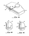
- FIGS. 4A-4C there is illustrated another feature of the invention, namely a clutch handle arrangement which ensures against clutch engagement of a floppy disc 103 unless the floppy disc is fully and properly seated within a floppy disc-containing and-positioning portion which is part of the overall assembly.
- the clutch indicated at 106, is a conventional clutch which contains a conical member (not shown) which seats down into the central opening of the floppy disc 103 and causes it to be pressed into contact with the drive ring 68 shown in Fig. 1.
- the clutch is operated by a handle 107, seen in Figure 4A, which connects through an axle 108 and an appropriate camming mechanism not shown.
- the handle 107 which at the 9 o'clock position (shown in Figure 4A) is above the floppy disc 103, can be rotated downward for clutch engagement only if the floppy disc 103 is fully inserted into an opening 102 in portion 101 such that the floppy disc is properly centered.
- Figure 4B if the floppy disc 103 is not fully inserted, the forward extended portion 110 of handle 107 does not clear the floppy disc, and clutch engagement is not possible.
- portion 110 of handle 107 clears the proximal edge of the disc, enabling rotation of the handle with consequent clutch engagement.
- Another feature of the invention lies in the provision of means for detecting when the read head 88, 90 is positioned in registration with the zero track of a floppy disc.
- Lower read head member 90 ( Figure 2) carries an outward extension 91 which intercepts fixed photodetector 77 when and only when the read head is positioned over the zero track.
- the detector output is carried through connector 73 to the electronic control board (not shown) so that the drive always shows when the read head is positioned at the zero track.
- the invention provides a highly efficient and relatively compact direct rotation floppy disc drive assembly.
- the invention gives rise to a thinner motor than previously available, thereby reducing the size of the overall drive package. Construction is also simplified, resulting in less expense. For example, motor pale pieces are fabricated integrally with the base plate of the overall assembly.
Landscapes
- Engineering & Computer Science (AREA)
- Power Engineering (AREA)
- Rotational Drive Of Disk (AREA)
- Holding Or Fastening Of Disk On Rotational Shaft (AREA)
Applications Claiming Priority (2)
| Application Number | Priority Date | Filing Date | Title |
|---|---|---|---|
| US06/019,901 US4275426A (en) | 1979-03-12 | 1979-03-12 | Floppy disc drive |
| US19901 | 1979-03-12 |
Publications (1)
| Publication Number | Publication Date |
|---|---|
| EP0015764A1 true EP0015764A1 (fr) | 1980-09-17 |
Family
ID=21795658
Family Applications (1)
| Application Number | Title | Priority Date | Filing Date |
|---|---|---|---|
| EP80300706A Withdrawn EP0015764A1 (fr) | 1979-03-12 | 1980-03-07 | Dispositif d'entraînement pour disques souples |
Country Status (5)
| Country | Link |
|---|---|
| US (1) | US4275426A (fr) |
| EP (1) | EP0015764A1 (fr) |
| JP (1) | JPS55125576A (fr) |
| AU (1) | AU5631780A (fr) |
| BR (1) | BR8001437A (fr) |
Cited By (3)
| Publication number | Priority date | Publication date | Assignee | Title |
|---|---|---|---|---|
| WO1983002042A1 (fr) * | 1981-12-04 | 1983-06-09 | Oudet, Claude | Moteur pas a pas electrique |
| EP0270477A3 (fr) * | 1986-12-02 | 1989-10-25 | Mueller And Smith, Lpa | Moteur à courant continu |
| GB2379093A (en) * | 2001-08-22 | 2003-02-26 | Chia-Hao Fan | Side rotation (axial) type motor/dynamo |
Families Citing this family (10)
| Publication number | Priority date | Publication date | Assignee | Title |
|---|---|---|---|---|
| JPS56130861A (en) * | 1980-03-17 | 1981-10-14 | Victor Co Of Japan Ltd | Reproducing device for information recording medium |
| JPS58177555A (ja) * | 1982-04-12 | 1983-10-18 | Teac Co | 記録媒体デイスク駆動装置 |
| US4573091A (en) * | 1982-11-15 | 1986-02-25 | Cipher Data Products, Inc. | Cartridge tape drive |
| JPS6098165U (ja) * | 1983-12-02 | 1985-07-04 | アルプス電気株式会社 | フレキシブルデイスク装置 |
| US5124863A (en) * | 1989-06-27 | 1992-06-23 | Canon Denshi Kabushiki Kaisha | Disk drive device having reduced thickness |
| US5291357A (en) * | 1990-06-29 | 1994-03-01 | Nippon Densan Corporation | Magnetic recording device having reduced electromagnetic interference |
| JP3157850B2 (ja) * | 1991-04-12 | 2001-04-16 | 日本電産株式会社 | スピンドルモータ |
| US5519270A (en) * | 1992-08-19 | 1996-05-21 | Fujitsu Limited | Spindle motor and disk drive having the same |
| JP2002227841A (ja) * | 2001-01-30 | 2002-08-14 | Namiki Precision Jewel Co Ltd | 小型扁平モータ用流体動圧軸受、小型扁平モータ、ファンモータ、空気強制供給型空気電池 |
| JP3708898B2 (ja) * | 2002-04-24 | 2005-10-19 | 株式会社東芝 | ディスク回転用モータ、およびディスク装置 |
Citations (13)
| Publication number | Priority date | Publication date | Assignee | Title |
|---|---|---|---|---|
| DE534319C (de) * | 1924-12-16 | 1931-09-24 | Eduard Uller | Elektrischer Stromerzeuger |
| US2432070A (en) * | 1944-12-18 | 1947-12-02 | Arthur H Sanborn | Synchronous motor |
| US2484001A (en) * | 1945-11-20 | 1949-10-04 | Gen Aniline & Film Corp | Motor field frame and method of fabrication |
| US2552315A (en) * | 1949-01-21 | 1951-05-08 | Gibraltar Mfg Co Inc | Self-starting synchronous electric motor |
| US3226584A (en) * | 1960-06-10 | 1965-12-28 | Intron Int Inc | Induced-quadrature field synchronous motor |
| FR1592065A (fr) * | 1967-01-25 | 1970-05-11 | ||
| DE1763112A1 (de) * | 1968-04-03 | 1971-07-01 | Licentia Gmbh | Stellantrieb,insbesondere fuer Potentiometer |
| US3833926A (en) * | 1972-11-10 | 1974-09-03 | Arvin Ind Inc | Magnetic disc recorder and cassette with compliant recording disc having flexible support means |
| FR2225804A1 (fr) * | 1973-04-11 | 1974-11-08 | Ted Bildplatten | |
| USB352950I5 (fr) * | 1972-04-20 | 1975-01-28 | ||
| US3869626A (en) * | 1971-09-27 | 1975-03-04 | Emi Ltd | Dynamo electric machines |
| US3959823A (en) * | 1974-11-18 | 1976-05-25 | Dynastor, Inc. | Flexible disc receiver using a tray which is withdrawn from a cartridge |
| DE2541694A1 (de) * | 1975-09-18 | 1977-03-24 | Siemens Ag | Elektrische maschine mit axialem luftspalt |
Family Cites Families (5)
| Publication number | Priority date | Publication date | Assignee | Title |
|---|---|---|---|---|
| US3500363A (en) * | 1966-07-11 | 1970-03-10 | Singer Co | Scanning apparatus |
| US3886595A (en) * | 1974-02-13 | 1975-05-27 | Information Storage Systems | Actuator for a disc drive apparatus |
| US3881184A (en) * | 1974-05-28 | 1975-04-29 | Ibm | Adaptive digital servo system |
| USRE29380E (en) | 1975-01-31 | 1977-08-30 | International Business Machines Corporation | Recording apparatus for magnetic disks using both sides of the disk |
| US4146912A (en) * | 1977-08-12 | 1979-03-27 | Perkin-Elmer Corporation | Disk interlock mechanism |
-
1979
- 1979-03-12 US US06/019,901 patent/US4275426A/en not_active Expired - Lifetime
-
1980
- 1980-03-07 EP EP80300706A patent/EP0015764A1/fr not_active Withdrawn
- 1980-03-11 AU AU56317/80A patent/AU5631780A/en not_active Abandoned
- 1980-03-11 BR BR8001437A patent/BR8001437A/pt unknown
- 1980-03-12 JP JP3044580A patent/JPS55125576A/ja active Pending
Patent Citations (13)
| Publication number | Priority date | Publication date | Assignee | Title |
|---|---|---|---|---|
| DE534319C (de) * | 1924-12-16 | 1931-09-24 | Eduard Uller | Elektrischer Stromerzeuger |
| US2432070A (en) * | 1944-12-18 | 1947-12-02 | Arthur H Sanborn | Synchronous motor |
| US2484001A (en) * | 1945-11-20 | 1949-10-04 | Gen Aniline & Film Corp | Motor field frame and method of fabrication |
| US2552315A (en) * | 1949-01-21 | 1951-05-08 | Gibraltar Mfg Co Inc | Self-starting synchronous electric motor |
| US3226584A (en) * | 1960-06-10 | 1965-12-28 | Intron Int Inc | Induced-quadrature field synchronous motor |
| FR1592065A (fr) * | 1967-01-25 | 1970-05-11 | ||
| DE1763112A1 (de) * | 1968-04-03 | 1971-07-01 | Licentia Gmbh | Stellantrieb,insbesondere fuer Potentiometer |
| US3869626A (en) * | 1971-09-27 | 1975-03-04 | Emi Ltd | Dynamo electric machines |
| USB352950I5 (fr) * | 1972-04-20 | 1975-01-28 | ||
| US3833926A (en) * | 1972-11-10 | 1974-09-03 | Arvin Ind Inc | Magnetic disc recorder and cassette with compliant recording disc having flexible support means |
| FR2225804A1 (fr) * | 1973-04-11 | 1974-11-08 | Ted Bildplatten | |
| US3959823A (en) * | 1974-11-18 | 1976-05-25 | Dynastor, Inc. | Flexible disc receiver using a tray which is withdrawn from a cartridge |
| DE2541694A1 (de) * | 1975-09-18 | 1977-03-24 | Siemens Ag | Elektrische maschine mit axialem luftspalt |
Non-Patent Citations (1)
| Title |
|---|
| IBM TECHNICAL DISCLOSURE BULLETIN, IBM Corporation, Vol. 20, No. 10, March 1978 New York US J.L. NEUBAUER: "Low Profile Diskette Drive", pages 4066-4068 * Page 4066, lines 5-10 * * |
Cited By (5)
| Publication number | Priority date | Publication date | Assignee | Title |
|---|---|---|---|---|
| WO1983002042A1 (fr) * | 1981-12-04 | 1983-06-09 | Oudet, Claude | Moteur pas a pas electrique |
| FR2517897A1 (fr) * | 1981-12-04 | 1983-06-10 | Portescap | Moteur pas a pas electrique |
| US4518883A (en) * | 1981-12-04 | 1985-05-21 | Portescap | Electric motor with permanent magnet rotor |
| EP0270477A3 (fr) * | 1986-12-02 | 1989-10-25 | Mueller And Smith, Lpa | Moteur à courant continu |
| GB2379093A (en) * | 2001-08-22 | 2003-02-26 | Chia-Hao Fan | Side rotation (axial) type motor/dynamo |
Also Published As
| Publication number | Publication date |
|---|---|
| US4275426A (en) | 1981-06-23 |
| JPS55125576A (en) | 1980-09-27 |
| AU5631780A (en) | 1980-09-18 |
| BR8001437A (pt) | 1980-11-11 |
Similar Documents
| Publication | Publication Date | Title |
|---|---|---|
| US4275426A (en) | Floppy disc drive | |
| US4359763A (en) | Floppy disc drive | |
| US5251082A (en) | Miniaturized disk file pluggable into a card terminal | |
| EP0698879A1 (fr) | Module à disque magnétique | |
| US5257151A (en) | Disc-drive with a rim-motor | |
| SU1128846A3 (ru) | Кассетное устройство дл записи информации | |
| JPH01287875A (ja) | 情報処理装置 | |
| US5982061A (en) | Spindle motor with two-piece shaft and connector | |
| US4570254A (en) | Drive motor having moving rotor for compact disc player apparatus | |
| US5233296A (en) | Floppy disk drive revolution detector avoiding interference with magnetic circuit | |
| US4669008A (en) | Disk support device | |
| KR890006303Y1 (ko) | 디스크 구동장치 | |
| US4107745A (en) | Tape speed control apparatus | |
| JPH09312058A (ja) | フレキシブルディスクドライブ用スピンドルモータおよびそのバランス調整方法 | |
| US3074724A (en) | Apparatus for positioning recording and recorded sheets on a magnetic recorder and reproducer | |
| US5337608A (en) | Drive roller torque reference cartridge | |
| US3936879A (en) | Cartridge type plaint disc apparatus | |
| EP0232588A2 (fr) | Appareil, système et méthode d'enregistrement et de reproduction magnétique | |
| HK20297A (en) | Turntable device for an information disc | |
| US6765754B2 (en) | Flexible disk drive comprising an index detection hall element having an improved detection sensitive condition of a magnetic field | |
| JPS634285Y2 (fr) | ||
| EP0243973A2 (fr) | Lecteur de disques compact | |
| JPH0240612Y2 (fr) | ||
| JPH0250348A (ja) | 記録または再生装置 | |
| JPH0355176Y2 (fr) |
Legal Events
| Date | Code | Title | Description |
|---|---|---|---|
| PUAI | Public reference made under article 153(3) epc to a published international application that has entered the european phase |
Free format text: ORIGINAL CODE: 0009012 |
|
| AK | Designated contracting states |
Designated state(s): BE CH DE FR GB IT NL |
|
| STAA | Information on the status of an ep patent application or granted ep patent |
Free format text: STATUS: THE APPLICATION IS DEEMED TO BE WITHDRAWN |
|
| 18D | Application deemed to be withdrawn |
Effective date: 19811118 |
|
| RIN1 | Information on inventor provided before grant (corrected) |
Inventor name: HOFFMAN, PAUL RUSSELL |