EP0016268B1 - Verschliessbare Gelenkverbindung für Gliedmassenstützen und andere orthopädische Zwecke - Google Patents
Verschliessbare Gelenkverbindung für Gliedmassenstützen und andere orthopädische Zwecke Download PDFInfo
- Publication number
- EP0016268B1 EP0016268B1 EP79300423A EP79300423A EP0016268B1 EP 0016268 B1 EP0016268 B1 EP 0016268B1 EP 79300423 A EP79300423 A EP 79300423A EP 79300423 A EP79300423 A EP 79300423A EP 0016268 B1 EP0016268 B1 EP 0016268B1
- Authority
- EP
- European Patent Office
- Prior art keywords
- joint
- detent
- recess
- channel
- shoulder
- Prior art date
- Legal status (The legal status is an assumption and is not a legal conclusion. Google has not performed a legal analysis and makes no representation as to the accuracy of the status listed.)
- Expired
Links
- 229910000831 Steel Inorganic materials 0.000 description 10
- 239000010959 steel Substances 0.000 description 10
- 210000003414 extremity Anatomy 0.000 description 9
- 230000007246 mechanism Effects 0.000 description 9
- 210000000887 face Anatomy 0.000 description 8
- 210000002414 leg Anatomy 0.000 description 7
- 210000000689 upper leg Anatomy 0.000 description 7
- 210000003127 knee Anatomy 0.000 description 5
- 210000000629 knee joint Anatomy 0.000 description 5
- 230000001154 acute effect Effects 0.000 description 3
- 244000309466 calf Species 0.000 description 2
- 210000003128 head Anatomy 0.000 description 2
- 238000004519 manufacturing process Methods 0.000 description 2
- 230000002093 peripheral effect Effects 0.000 description 2
- 230000007423 decrease Effects 0.000 description 1
- 230000000994 depressogenic effect Effects 0.000 description 1
- 239000002184 metal Substances 0.000 description 1
- 230000004048 modification Effects 0.000 description 1
- 238000012986 modification Methods 0.000 description 1
Images
Classifications
-
- A—HUMAN NECESSITIES
- A61—MEDICAL OR VETERINARY SCIENCE; HYGIENE
- A61F—FILTERS IMPLANTABLE INTO BLOOD VESSELS; PROSTHESES; DEVICES PROVIDING PATENCY TO, OR PREVENTING COLLAPSING OF, TUBULAR STRUCTURES OF THE BODY, e.g. STENTS; ORTHOPAEDIC, NURSING OR CONTRACEPTIVE DEVICES; FOMENTATION; TREATMENT OR PROTECTION OF EYES OR EARS; BANDAGES, DRESSINGS OR ABSORBENT PADS; FIRST-AID KITS
- A61F2/00—Filters implantable into blood vessels; Prostheses, i.e. artificial substitutes or replacements for parts of the body; Appliances for connecting them with the body; Devices providing patency to, or preventing collapsing of, tubular structures of the body, e.g. stents
- A61F2/50—Prostheses not implantable in the body
- A61F2/60—Artificial legs or feet or parts thereof
- A61F2/64—Knee joints
-
- A—HUMAN NECESSITIES
- A61—MEDICAL OR VETERINARY SCIENCE; HYGIENE
- A61F—FILTERS IMPLANTABLE INTO BLOOD VESSELS; PROSTHESES; DEVICES PROVIDING PATENCY TO, OR PREVENTING COLLAPSING OF, TUBULAR STRUCTURES OF THE BODY, e.g. STENTS; ORTHOPAEDIC, NURSING OR CONTRACEPTIVE DEVICES; FOMENTATION; TREATMENT OR PROTECTION OF EYES OR EARS; BANDAGES, DRESSINGS OR ABSORBENT PADS; FIRST-AID KITS
- A61F5/00—Orthopaedic methods or devices for non-surgical treatment of bones or joints; Nursing devices ; Anti-rape devices
- A61F5/01—Orthopaedic devices, e.g. long-term immobilising or pressure directing devices for treating broken or deformed bones such as splints, casts or braces
- A61F5/0102—Orthopaedic devices, e.g. long-term immobilising or pressure directing devices for treating broken or deformed bones such as splints, casts or braces specially adapted for correcting deformities of the limbs or for supporting them; Ortheses, e.g. with articulations
- A61F5/0123—Orthopaedic devices, e.g. long-term immobilising or pressure directing devices for treating broken or deformed bones such as splints, casts or braces specially adapted for correcting deformities of the limbs or for supporting them; Ortheses, e.g. with articulations for the knees
- A61F5/0125—Orthopaedic devices, e.g. long-term immobilising or pressure directing devices for treating broken or deformed bones such as splints, casts or braces specially adapted for correcting deformities of the limbs or for supporting them; Ortheses, e.g. with articulations for the knees the device articulating around a single pivot-point
-
- E—FIXED CONSTRUCTIONS
- E05—LOCKS; KEYS; WINDOW OR DOOR FITTINGS; SAFES
- E05D—HINGES OR SUSPENSION DEVICES FOR DOORS, WINDOWS OR WINGS
- E05D11/00—Additional features or accessories of hinges
- E05D11/10—Devices for preventing movement between relatively-movable hinge parts
- E05D11/1007—Devices for preventing movement between relatively-movable hinge parts with positive locking
-
- A—HUMAN NECESSITIES
- A61—MEDICAL OR VETERINARY SCIENCE; HYGIENE
- A61F—FILTERS IMPLANTABLE INTO BLOOD VESSELS; PROSTHESES; DEVICES PROVIDING PATENCY TO, OR PREVENTING COLLAPSING OF, TUBULAR STRUCTURES OF THE BODY, e.g. STENTS; ORTHOPAEDIC, NURSING OR CONTRACEPTIVE DEVICES; FOMENTATION; TREATMENT OR PROTECTION OF EYES OR EARS; BANDAGES, DRESSINGS OR ABSORBENT PADS; FIRST-AID KITS
- A61F2/00—Filters implantable into blood vessels; Prostheses, i.e. artificial substitutes or replacements for parts of the body; Appliances for connecting them with the body; Devices providing patency to, or preventing collapsing of, tubular structures of the body, e.g. stents
- A61F2/50—Prostheses not implantable in the body
- A61F2/68—Operating or control means
- A61F2002/6854—Operating or control means for locking or unlocking a joint
-
- A—HUMAN NECESSITIES
- A61—MEDICAL OR VETERINARY SCIENCE; HYGIENE
- A61F—FILTERS IMPLANTABLE INTO BLOOD VESSELS; PROSTHESES; DEVICES PROVIDING PATENCY TO, OR PREVENTING COLLAPSING OF, TUBULAR STRUCTURES OF THE BODY, e.g. STENTS; ORTHOPAEDIC, NURSING OR CONTRACEPTIVE DEVICES; FOMENTATION; TREATMENT OR PROTECTION OF EYES OR EARS; BANDAGES, DRESSINGS OR ABSORBENT PADS; FIRST-AID KITS
- A61F5/00—Orthopaedic methods or devices for non-surgical treatment of bones or joints; Nursing devices ; Anti-rape devices
- A61F5/01—Orthopaedic devices, e.g. long-term immobilising or pressure directing devices for treating broken or deformed bones such as splints, casts or braces
- A61F5/0102—Orthopaedic devices, e.g. long-term immobilising or pressure directing devices for treating broken or deformed bones such as splints, casts or braces specially adapted for correcting deformities of the limbs or for supporting them; Ortheses, e.g. with articulations
- A61F2005/0132—Additional features of the articulation
- A61F2005/0158—Additional features of the articulation with locking means
-
- A—HUMAN NECESSITIES
- A61—MEDICAL OR VETERINARY SCIENCE; HYGIENE
- A61F—FILTERS IMPLANTABLE INTO BLOOD VESSELS; PROSTHESES; DEVICES PROVIDING PATENCY TO, OR PREVENTING COLLAPSING OF, TUBULAR STRUCTURES OF THE BODY, e.g. STENTS; ORTHOPAEDIC, NURSING OR CONTRACEPTIVE DEVICES; FOMENTATION; TREATMENT OR PROTECTION OF EYES OR EARS; BANDAGES, DRESSINGS OR ABSORBENT PADS; FIRST-AID KITS
- A61F5/00—Orthopaedic methods or devices for non-surgical treatment of bones or joints; Nursing devices ; Anti-rape devices
- A61F5/01—Orthopaedic devices, e.g. long-term immobilising or pressure directing devices for treating broken or deformed bones such as splints, casts or braces
- A61F5/0102—Orthopaedic devices, e.g. long-term immobilising or pressure directing devices for treating broken or deformed bones such as splints, casts or braces specially adapted for correcting deformities of the limbs or for supporting them; Ortheses, e.g. with articulations
- A61F2005/0132—Additional features of the articulation
- A61F2005/0158—Additional features of the articulation with locking means
- A61F2005/016—Additional features of the articulation with locking means in standing position
-
- E—FIXED CONSTRUCTIONS
- E05—LOCKS; KEYS; WINDOW OR DOOR FITTINGS; SAFES
- E05Y—INDEXING SCHEME ASSOCIATED WITH SUBCLASSES E05D AND E05F, RELATING TO CONSTRUCTION ELEMENTS, ELECTRIC CONTROL, POWER SUPPLY, POWER SIGNAL OR TRANSMISSION, USER INTERFACES, MOUNTING OR COUPLING, DETAILS, ACCESSORIES, AUXILIARY OPERATIONS NOT OTHERWISE PROVIDED FOR, APPLICATION THEREOF
- E05Y2999/00—Subject-matter not otherwise provided for in this subclass
Definitions
- the present invention relates to a lockable joint which is particularly, but not exclusively, useful as a knee joint of an orthopaedic leg support.
- a leg brace includes thigh supports ("steels") to either side of the thigh and calf steels to either side of the lower part of the leg, the thigh and shank steels on each side of the leg being connected by a pivot joint at knee level.
- the pivot joint on one or both sides of the knee is arranged to be locked when the patient is standing or walking but has to be releaseable to allow the knee joint to flex when the patient is sitting.
- the release mechanism may be operated by a ring catch or drop lock which is a sliding ring on the thigh steel which may be lowered into engagement with the pivot joint to lock it and which is lifted to release the joint.
- bar lock Another kind of lock known as a bar lock or French lock involves a hinged release member pivoted to the thigh steel and operated by lifting an extension bar attached to the release member.
- bar locks are used, the pivot joints on both sides of the knee are normally lockable and the release members on opposite sides of the knee are interconnected by means of a bar extending around the back of the knee.
- a further kind of release mechanism employs a hinged release member having an extension bar to which a lifting cable may be fixed. The patient's disability may often affect parts of his body other than his legs, and the orthopaedic fitter has to select from the range of available release mechanisms one which is within the patient's capacity to operate.
- release mechanisms and in particular the ring catch and bar lock mechanisms operate on different principles and require differently shaped hinge members.
- Manually operated ring catches are not normally spring loaded into the locked position and suffer from the disadvantage that they may accidentally be shaken out of engagement while the patient is walking.
- the joint of the invention may be released by upward finger pressure like a manual ring catch but the release member is spring loaded into the locked position.
- a further disadvantage of currently available ring catches is that although they may have little play when new, significant play is liable to develop as a result of wear, but such a tendency is not significantly exhibited by the hinge joint of the invention.
- U.S. Patent No. 2591373 describes a lockable knee joint for an artificial limb in which the lower end of an upper brace member is secured to a sleeve provided with circular extensions that project downwardly in lapped relationship on each side of the upper end of a lower brace member, the two being connected by a hinge pin for relative flexing movement.
- the upper end of the lower brace member is provided with an anteriorly disposed segmental arcuate bearing surface concentric with the hinge pin and a posterior arcuate recess inwards of the arcuate bearing surface.
- the upper brace member is provided with a locking lug that projects downwardly into the arcuate recess and in the unflexed position of the joint abuts the posterior end of the arcuate bearing surface to prevent movement beyond the unflexed position.
- the arcuate bearing surface terminates at its anterior end in an anterior recess which aligns with a slot in the upper member when the joint is unflexed and extends axially away from said recess.
- a detent is resiliently biased by a spring into a position where it engages the anterior recess to prevent unintentional joint flexion and is retractible into the slot by pulling on a knob that raises a narrow metal lock operating finger connected to detent through a pin so that the detent, pin and operating finger slide up and down together.
- the detent is supported or supportable on the arcuate bearing surface when the joint is flexed and is urged into engagement with the recess when the joint is straightened to lock the joint in the unflexed position. But the detent is not lever-actuated and is unsuitable for lever actuation because both the detent and the slot are located at the front edge of the joint.
- the invention provides a releasably lockable joint for an orthopaedic limb support or for an artificial limb, which joint comprises first and second members pivoted together at their ends for relative flexing movement and having stop faces which abut when the joint is straight to prevent movement beyond the straight position, the pivoted end of the first member having an arcuate portion which terminates in a recess or shoulder and the second member having a channel which is in register with the base of said recess or shoulder when the joint is straight and which extends away from the recess or shoulder, a detent slidable in the channel so that it may be retracted into the channel by operation of a release and is supported or supportable in its retracted position by said arcuate portion when the joint is flexed but is urged by reslient means into engagement with said recess or shoulder when the joint is straightened to lock the joint in the straight position, characterised in that the release for the detent is a lever pivoted at one end to one longitudinal edge of the second member
- the lockable joint may additionally comprise a releaseable catch for locking the detent in the retracted position.
- a catch may comprise an auxiliary channel in the second member opening into the detent channel, a ball catch in the auxiliary channel resiliently biased to project therefrom and a recess in the detent positioned to be engaged by the ball of the ball catch when the detent is retracted.
- the detent is preferably wedge shaped, with its rear face which engages an upwardly directed locking face of the recess or shoulder in the first member inclined at a small acute angle typically of the order of 10 degrees with respect to the other face thereof, the locking face of the recess or shoulder being directed parallel to the inclined face of the detent when the joint is straight so that when the detent is slid into engagement with the shoulder or recess, its inclined face is wedged against the lock face which wedging action minimises play in the pivot.
- interengaging faces of the detent and the shoulder or recess may be directed at approximately a right angle to the stop faces when the joint is in the straight position and the interengaging faces and the stop faces are a quarter.circie removed from one another with respect to the pivot axis and so exert a wedging action taking up any play in the pivot.
- the release lever is preferably in the form of an external ring fitted to the second member with its front edge pivotally received in a recess in the front edge of the second member and the internal surface of its rear edge normally spaced from the rear edge of the second member, an upward movement of the rear edge of the ring retracting the detent into the channel.
- the rear portion of the ring may be further provided with a socket for receiving an extension lever which forms part of a bar lock or cable lift.
- the joint is manufactured as a sub-assembly separate from the steels of the limb support into which it is to be incorporated.
- the outer ends of the first and second members are preferably formed with a internal axial channel dimensioned to receive the end of the respective steel which is then screwed or riveted in place.
- the end of the member may have its sides split longitudinally so that fixing screws can be passed through each side of the member and through the steel to force the sides together and clamp the steel rigidly therebetween.
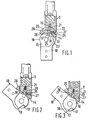
- a knee joint for attachment to side steels of an orthopaedic leg brace comprises a first or calf member 10 having a head in the form of an eye-bolt pivoted to a second or thigh member 11 by means of a pivot bush (not shown) which passes through the eyes of the bolt heads and is held in place by means of a locking screw 12 (Figure 4).
- the head of the member 11 is split to form a fork bracket having two transversely spaced apart circular leaves which, as is apparent from Figure 4(lla) are angled rearwardly so that the centre of the locking screw 12 is offset a small distance rearwardly of the longitudinal centre line of the thigh member 11.
- the forward end of the member 11 extends beyond the base of the two-leaf fork brackets to define a transversely directed limit face 14.
- the eye-bolt portion of the member 10 is formed with a zone 15 of reduced thickness which fits between the leaves of the fork bracket and has at its front edge a full thickness region outside the periphery of the leaves and bounded at its upper end by a transversely directed stop face 13.
- the stop faces 13 and 14 abut when the joint is unflexed to prevent further relative angular movement of the members 10 and 11.
- the stop face 13 is formed on a portion of the member 10 which is of full thickness so that there is an ample area of contact with the stop face 14, and the faces 13 and 14 are well spaced from the pivot axis of the joint so that the unit load on the faces 13 and 14 in the unflexed joint is low and the rate of wear is minimised. It will be noted that in the unflexed joint the axis of the member 11 is generally parallel to and offset forwardly of the axis of the member 10.
- the eye-bolt portion of the member 10 is formed with an outer peripheral edge 16 of the zone of reduced thickness which terminates in a shoulder defined by a lock face 17 directed inwardly parallel to the longitudinal direction of the member 10 and a transverse face 18 which is continuous with the stop face 13.
- a rectangular slot or channel 19 in the member 11 is directed at a small acute angle, typically about 10 degrees, to the axis of the member 11 with Its lower end positioned so that its rear transverse face registers with the lock face 17 on member 10 when the joint is unflexed.
- a locking plunger or detent 20 slidable in the channel 19 is urged into locking engagement with the lock face 17 by means of a spring 21.
- the rear face of the detent is directed at a small acute angle (typically about 10 degrees) with respect to the longitudinal direction of the channel 19 and is parallel to the lock face 17 on the member 10 when the joint is In the straight position.
- the detent 20 is dimensioned to engage the lock face 17 with its end clear of the bottom face 18 and exerts a wedging action on the lock face 17 when the joint Is unflexed so that there is minimal play.
- the detent and lock face engage over a distance of 3 mm or more and when the joint Is new there is a distance of 1.5 mm or more between the end face of the detent and the bottom face 18 of the shoulder for wear take-up.
- the joint has the advantage that wear of the detent and lock face does not give rise to play but Instead the wear is automatically taken up by engagement of the wedge with the lock face 17 at a detent position closer to the bottom face 18 of the shoulder than it occupied when the joint was new.
- Figures 1 and 2 illustrate a joint which is arranged to be held unlocked until deliberately set to lock.
- An auxiliary bore 22 extends into the channel 19 from the front face of member 11 and has a catch formed by a ball 23 and spring 24 which as shown in Figure 2 urges the ball 23 into engagement with a rebate 25 in the front face of the detent 20 to hold the detent in a retracted position.
- An actuating ring 26 is fitted over the member 11 with its front portion pivotally received in a recess 27 in the front edge of the member 11 and is connected at an intermediate position to the detent 20 by means of a pivot pin 28.
- the actuating ring In the locked position shown in Figure 1 the actuating ring is urged downwardly by means of the detent spring 21 but its rear face may be lifted as shown in Figure 2 to retract the detent 20 into the channel 19 and compress the spring 21.
- the joint In use as a knee joint of an orthopaedic leg brace, the joint Is locked when the patient is standing or walking.
- the rear end of the actuating ring When he or she wishes to sit down, the rear end of the actuating ring is lifted to retract the detent out of engagement with the lock face 17 and into the channel 19 where it is held in a retracted position by engagement of the ball catch 23, 24 with the rebate 25.
- the rear end of the actuating ring is depressed to disengage the ball catch and allow the detent to snap downwardly into engagement with the lock face 17 to lock the joint against flexing.
- FIG. 3 The arrangement shown in Figure 3 is generally similar to that shown in Figures 1 and 2 except that the ball 23 and ball spring 24 have been omitted.
- the actuating ring 26 When the actuating ring 26 has been operated to retract the detent the joint may be flexed as shown in Figure 3.
- the detent On release of the actuating ring the detent is supported in a partially retracted position by the arcuate peripheral edge 16 and the members 10 and 11 may be straightened.
- the detent 20 automatically snaps into engagement with the lock face 17 to lock the joint against flexing.
- the joint is preferred to manufacture as a separate sub-assembly to be fitted into the limb brace or artificial limb.
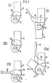
- Figures 4(1) and 4(lll) show two different shapes of hinged ring catch 26 fitted to the member 11, lifting the rear face causing the joint to unlock.
- finger pressure is applied to the back of the actuating ring 26 and in Figure 4(lll) finger pressure is applied to a rear side portion thereof.
- Figures 4(li) and 4(lla) show the actuating ring 26 fitted with an extension bar 31 and arranged to operate as a bar lock.
- Figure 4(iV) shows the member 26 having an extension 32 whose distal end is formed with an eye for fixing the cable of a cable lift system.
Landscapes
- Health & Medical Sciences (AREA)
- Engineering & Computer Science (AREA)
- Public Health (AREA)
- Life Sciences & Earth Sciences (AREA)
- Veterinary Medicine (AREA)
- Transplantation (AREA)
- Biomedical Technology (AREA)
- Heart & Thoracic Surgery (AREA)
- Vascular Medicine (AREA)
- Orthopedic Medicine & Surgery (AREA)
- Animal Behavior & Ethology (AREA)
- General Health & Medical Sciences (AREA)
- Cardiology (AREA)
- Oral & Maxillofacial Surgery (AREA)
- Nursing (AREA)
- Mechanical Engineering (AREA)
- Prostheses (AREA)
Claims (4)
Priority Applications (3)
| Application Number | Priority Date | Filing Date | Title |
|---|---|---|---|
| GB28720/77A GB1586302A (en) | 1977-07-08 | 1977-07-08 | Lockable hinge joint for limb supports and other orthopaedic appliances |
| DE7979300423T DE2965600D1 (en) | 1977-07-08 | 1979-03-16 | Lockable hinge joint for limb supports and other orthopaedic appliances |
| EP79300423A EP0016268B1 (de) | 1977-07-08 | 1979-03-16 | Verschliessbare Gelenkverbindung für Gliedmassenstützen und andere orthopädische Zwecke |
Applications Claiming Priority (2)
| Application Number | Priority Date | Filing Date | Title |
|---|---|---|---|
| GB28720/77A GB1586302A (en) | 1977-07-08 | 1977-07-08 | Lockable hinge joint for limb supports and other orthopaedic appliances |
| EP79300423A EP0016268B1 (de) | 1977-07-08 | 1979-03-16 | Verschliessbare Gelenkverbindung für Gliedmassenstützen und andere orthopädische Zwecke |
Publications (2)
| Publication Number | Publication Date |
|---|---|
| EP0016268A1 EP0016268A1 (de) | 1980-10-01 |
| EP0016268B1 true EP0016268B1 (de) | 1983-06-08 |
Family
ID=39587975
Family Applications (1)
| Application Number | Title | Priority Date | Filing Date |
|---|---|---|---|
| EP79300423A Expired EP0016268B1 (de) | 1977-07-08 | 1979-03-16 | Verschliessbare Gelenkverbindung für Gliedmassenstützen und andere orthopädische Zwecke |
Country Status (2)
| Country | Link |
|---|---|
| EP (1) | EP0016268B1 (de) |
| GB (1) | GB1586302A (de) |
Cited By (2)
| Publication number | Priority date | Publication date | Assignee | Title |
|---|---|---|---|---|
| US9351900B2 (en) | 2012-09-17 | 2016-05-31 | President And Fellows Of Harvard College | Soft exosuit for assistance with human motion |
| US11590046B2 (en) | 2016-03-13 | 2023-02-28 | President And Fellows Of Harvard College | Flexible members for anchoring to the body |
Families Citing this family (28)
| Publication number | Priority date | Publication date | Assignee | Title |
|---|---|---|---|---|
| GB2120101B (en) * | 1982-05-21 | 1985-07-31 | Kellie And Son Limited Robert | Knee joint |
| US4498838A (en) * | 1983-04-04 | 1985-02-12 | Towmotor Corporation | Retention device for a load engaging member |
| GB2168106B (en) * | 1984-12-06 | 1987-10-14 | Weston Hydraulics Ltd | Joint for orthotic device |
| GB8525303D0 (en) * | 1985-10-14 | 1985-11-20 | Hanger & Co Ltd J E | Artificial knee |
| US4958643A (en) * | 1989-06-16 | 1990-09-25 | Timothy Pansiera | Hinge joint |
| GB2235012B (en) * | 1989-08-09 | 1993-11-24 | Sec Dep For Health The | Orthotic device |
| FR2664493B1 (fr) * | 1990-07-10 | 1997-10-10 | Proteor Sa | Articulation pour orthese des membres inferieurs verrouillables en position d'extension de ces membres. |
| US5156630A (en) * | 1991-05-09 | 1992-10-20 | Rampro, Inc. | Ankle joint prosthesis fixable in more than one orientation |
| GB9305748D0 (en) * | 1993-03-19 | 1993-05-05 | Steeper Hugh Ltd | An orthotic caliper |
| GB2293861B (en) * | 1994-10-08 | 1998-03-18 | Pilkington Perkin Elmer Ltd | Locking device |
| GB9420335D0 (en) * | 1994-10-08 | 1995-03-08 | Pilkington Perkin Elmer Ltd | Locking device |
| DE9418858U1 (de) * | 1994-11-24 | 1996-03-28 | Paas, Dieter, Dipl.-Ing. (FH), 41464 Neuss | Gerät zum Trainieren des Gehens behinderter Personen |
| GB2301532A (en) * | 1995-06-02 | 1996-12-11 | Byrne Michael O | Knee frame for lower leg amputees |
| DE29715794U1 (de) * | 1997-09-03 | 1997-10-23 | Otto Bock Orthopädische Industrie Besitz- und Verwaltungs-Kommanditgesellschaft, 37115 Duderstadt | Orthesengelenk |
| GB2331462A (en) * | 1997-11-21 | 1999-05-26 | Blatchford & Sons Ltd | Knee Prosthesis with Locking Components |
| FR2826046A1 (fr) * | 2001-06-14 | 2002-12-20 | Tshiona Joseph Ntumba | Charniere a butee et immobilisation |
| US9033907B2 (en) | 2009-03-30 | 2015-05-19 | Aaron Matthew Noble | Adjustable hinge |
| DE102010046690B4 (de) | 2010-09-28 | 2012-04-19 | Otto Bock Healthcare Products Gmbh | Gelenkeinrichtung |
| CN102258406B (zh) * | 2011-04-26 | 2013-04-03 | 孙雁群 | 仿生护膝支具 |
| CN102885683B (zh) * | 2012-10-16 | 2014-06-18 | 国家康复辅具研究中心附属康复医院 | 高位截瘫肩动力迈步行走辅具用的关节自锁辅助行走装置 |
| WO2014194257A1 (en) | 2013-05-31 | 2014-12-04 | President And Fellows Of Harvard College | Soft exosuit for assistance with human motion |
| CN105992554A (zh) | 2013-12-09 | 2016-10-05 | 哈佛大学校长及研究员协会 | 帮助人移动的辅助柔性套服、柔性套服系统及它们的制造和控制方法 |
| EP3102171A4 (de) | 2014-02-05 | 2018-03-28 | President and Fellows of Harvard College | Systeme, verfahren und vorrichtung zur unterstützung des gehens für kleinkinder mit verzögerter entwicklung |
| US10864100B2 (en) | 2014-04-10 | 2020-12-15 | President And Fellows Of Harvard College | Orthopedic device including protruding members |
| JP6878271B2 (ja) | 2014-09-19 | 2021-05-26 | プレジデント アンド フェローズ オブ ハーバード カレッジ | 人の運動を補助するためのソフトエクソスーツ |
| US11498203B2 (en) | 2016-07-22 | 2022-11-15 | President And Fellows Of Harvard College | Controls optimization for wearable systems |
| US11014804B2 (en) | 2017-03-14 | 2021-05-25 | President And Fellows Of Harvard College | Systems and methods for fabricating 3D soft microstructures |
| IT201900014856A1 (it) * | 2019-08-20 | 2021-02-20 | Tenortho S R L Unipersonale | Snodo per articolazione |
Family Cites Families (4)
| Publication number | Priority date | Publication date | Assignee | Title |
|---|---|---|---|---|
| DE298767C (de) * | ||||
| US2591373A (en) * | 1950-12-16 | 1952-04-01 | Petruch Methodius Ciryllus | Lockable knee joint for orthopedic braces or artificial limbs |
| DE1193636B (de) * | 1962-03-09 | 1965-05-26 | Goetz Gerd Kuhn Dr Med | Kniegelenk fuer Prothesen, Apparateschienen u. dgl. |
| DE2119599C3 (de) * | 1971-04-22 | 1974-09-26 | Otto Bock Orthopaedische Industrie Kg, 3428 Duderstadt | Schaltvorrichtung für Gesperre orthopädischer Gelenke |
-
1977
- 1977-07-08 GB GB28720/77A patent/GB1586302A/en not_active Expired
-
1979
- 1979-03-16 EP EP79300423A patent/EP0016268B1/de not_active Expired
Cited By (2)
| Publication number | Priority date | Publication date | Assignee | Title |
|---|---|---|---|---|
| US9351900B2 (en) | 2012-09-17 | 2016-05-31 | President And Fellows Of Harvard College | Soft exosuit for assistance with human motion |
| US11590046B2 (en) | 2016-03-13 | 2023-02-28 | President And Fellows Of Harvard College | Flexible members for anchoring to the body |
Also Published As
| Publication number | Publication date |
|---|---|
| GB1586302A (en) | 1981-03-18 |
| EP0016268A1 (de) | 1980-10-01 |
Similar Documents
| Publication | Publication Date | Title |
|---|---|---|
| EP0016268B1 (de) | Verschliessbare Gelenkverbindung für Gliedmassenstützen und andere orthopädische Zwecke | |
| US6635024B2 (en) | Articulating knee supports | |
| CA2688458C (en) | Artificial joint with locking mechanism | |
| JP2787313B2 (ja) | 肢の運動を調整するための装具または義肢 | |
| US20060206045A1 (en) | Post operative knee brace with multiple adjustment features | |
| US5851194A (en) | Quick release mechanism for orthopedic limb brace | |
| US8728018B2 (en) | Post operative hinge brace | |
| US20030093018A1 (en) | Orthesis comprising a flexion and an extension stop that can be adjusted by means of rail pivoting movements | |
| AU773705B2 (en) | Gravity operated locking hinge | |
| US5244455A (en) | Knee hinge | |
| EP1996133A2 (de) | Verstellbare ergonomische schiene | |
| US2591373A (en) | Lockable knee joint for orthopedic braces or artificial limbs | |
| US11857394B2 (en) | Thigh prosthetic component | |
| US6510852B1 (en) | Headpiece for patient support | |
| US6299588B1 (en) | Quick release mechanism for orthopedic limb brace | |
| US7462159B1 (en) | Knee-ankle-foot orthotic device | |
| US11191659B2 (en) | Joint brace with improved range of motion stop | |
| EP0615734B1 (de) | Verriegelbare orthopädische Stütze | |
| US4237708A (en) | Prisoner leg restrainer | |
| US11187262B2 (en) | Hinge having a rotation-stop lock | |
| US6500139B1 (en) | Orthopedic knee brace joint assembly having a trigger locking mechanism | |
| IE47845B1 (en) | Lockable hinge joint for limb supports and other orthopaedic appliances | |
| EP0095872A1 (de) | Kniegelenke für künstliche Beine | |
| GB2151481A (en) | Lockable knee joint | |
| EP1086670A2 (de) | Gelenkorthese mit axial einstellbaren Bewegunsbereichen |
Legal Events
| Date | Code | Title | Description |
|---|---|---|---|
| PUAI | Public reference made under article 153(3) epc to a published international application that has entered the european phase |
Free format text: ORIGINAL CODE: 0009012 |
|
| AK | Designated contracting states |
Kind code of ref document: A1 Designated state(s): BE DE FR IT LU NL |
|
| 17P | Request for examination filed |
Effective date: 19810114 |
|
| ITF | It: translation for a ep patent filed | ||
| GRAA | (expected) grant |
Free format text: ORIGINAL CODE: 0009210 |
|
| AK | Designated contracting states |
Kind code of ref document: B1 Designated state(s): BE DE FR IT LU NL |
|
| REF | Corresponds to: |
Ref document number: 2965600 Country of ref document: DE Date of ref document: 19830714 |
|
| ET | Fr: translation filed | ||
| PGFP | Annual fee paid to national office [announced via postgrant information from national office to epo] |
Ref country code: LU Payment date: 19840207 Year of fee payment: 6 |
|
| PGFP | Annual fee paid to national office [announced via postgrant information from national office to epo] |
Ref country code: DE Payment date: 19840301 Year of fee payment: 6 |
|
| PGFP | Annual fee paid to national office [announced via postgrant information from national office to epo] |
Ref country code: FR Payment date: 19840330 Year of fee payment: 6 |
|
| PG25 | Lapsed in a contracting state [announced via postgrant information from national office to epo] |
Ref country code: LU Free format text: LAPSE BECAUSE OF NON-PAYMENT OF DUE FEES Effective date: 19840331 |
|
| PGFP | Annual fee paid to national office [announced via postgrant information from national office to epo] |
Ref country code: BE Payment date: 19840331 Year of fee payment: 6 |
|
| PLBE | No opposition filed within time limit |
Free format text: ORIGINAL CODE: 0009261 |
|
| STAA | Information on the status of an ep patent application or granted ep patent |
Free format text: STATUS: NO OPPOSITION FILED WITHIN TIME LIMIT |
|
| 26N | No opposition filed | ||
| PGFP | Annual fee paid to national office [announced via postgrant information from national office to epo] |
Ref country code: NL Payment date: 19850314 Year of fee payment: 7 |
|
| PG25 | Lapsed in a contracting state [announced via postgrant information from national office to epo] |
Ref country code: BE Effective date: 19860331 |
|
| BERE | Be: lapsed |
Owner name: ROBERT KELLIE & SON LTD Effective date: 19860331 |
|
| PG25 | Lapsed in a contracting state [announced via postgrant information from national office to epo] |
Ref country code: NL Effective date: 19861001 |
|
| PG25 | Lapsed in a contracting state [announced via postgrant information from national office to epo] |
Ref country code: FR Free format text: LAPSE BECAUSE OF NON-PAYMENT OF DUE FEES Effective date: 19861128 |
|
| PG25 | Lapsed in a contracting state [announced via postgrant information from national office to epo] |
Ref country code: DE Effective date: 19861202 |
|
| NLV4 | Nl: lapsed or anulled due to non-payment of the annual fee | ||
| REG | Reference to a national code |
Ref country code: FR Ref legal event code: ST |