EP0016419A1 - Capsule à vis pour récipients du type bouteille - Google Patents
Capsule à vis pour récipients du type bouteille Download PDFInfo
- Publication number
- EP0016419A1 EP0016419A1 EP80101287A EP80101287A EP0016419A1 EP 0016419 A1 EP0016419 A1 EP 0016419A1 EP 80101287 A EP80101287 A EP 80101287A EP 80101287 A EP80101287 A EP 80101287A EP 0016419 A1 EP0016419 A1 EP 0016419A1
- Authority
- EP
- European Patent Office
- Prior art keywords
- collar
- group
- cap
- shear
- closure cap
- Prior art date
- Legal status (The legal status is an assumption and is not a legal conclusion. Google has not performed a legal analysis and makes no representation as to the accuracy of the status listed.)
- Granted
Links
- 238000010008 shearing Methods 0.000 claims abstract description 13
- 210000002105 tongue Anatomy 0.000 claims description 12
- 230000007704 transition Effects 0.000 claims description 3
- 238000004519 manufacturing process Methods 0.000 abstract description 4
- 230000002028 premature Effects 0.000 abstract description 3
- 238000005452 bending Methods 0.000 description 2
- 238000001746 injection moulding Methods 0.000 description 2
- 230000002093 peripheral effect Effects 0.000 description 2
- 238000000926 separation method Methods 0.000 description 2
- -1 Polyethylene Polymers 0.000 description 1
- 239000004698 Polyethylene Substances 0.000 description 1
- 230000015572 biosynthetic process Effects 0.000 description 1
- 230000000903 blocking effect Effects 0.000 description 1
- 238000002347 injection Methods 0.000 description 1
- 239000007924 injection Substances 0.000 description 1
- 229920000573 polyethylene Polymers 0.000 description 1
- 238000007789 sealing Methods 0.000 description 1
- 238000007493 shaping process Methods 0.000 description 1
- 229920001169 thermoplastic Polymers 0.000 description 1
- 239000004416 thermosoftening plastic Substances 0.000 description 1
Images
Classifications
-
- B—PERFORMING OPERATIONS; TRANSPORTING
- B65—CONVEYING; PACKING; STORING; HANDLING THIN OR FILAMENTARY MATERIAL
- B65D—CONTAINERS FOR STORAGE OR TRANSPORT OF ARTICLES OR MATERIALS, e.g. BAGS, BARRELS, BOTTLES, BOXES, CANS, CARTONS, CRATES, DRUMS, JARS, TANKS, HOPPERS, FORWARDING CONTAINERS; ACCESSORIES, CLOSURES, OR FITTINGS THEREFOR; PACKAGING ELEMENTS; PACKAGES
- B65D41/00—Caps, e.g. crown caps or crown seals, i.e. members having parts arranged for engagement with the external periphery of a neck or wall defining a pouring opening or discharge aperture; Protective cap-like covers for closure members, e.g. decorative covers of metal foil or paper
- B65D41/32—Caps or cap-like covers with lines of weakness, tearing-strips, tags, or like opening or removal devices, e.g. to facilitate formation of pouring openings
- B65D41/34—Threaded or like caps or cap-like covers provided with tamper elements formed in, or attached to, the closure skirt
- B65D41/3404—Threaded or like caps or cap-like covers provided with tamper elements formed in, or attached to, the closure skirt with ratchet-and-pawl mechanism between the container and the closure skirt or the tamper element
- B65D41/3409—Threaded or like caps or cap-like covers provided with tamper elements formed in, or attached to, the closure skirt with ratchet-and-pawl mechanism between the container and the closure skirt or the tamper element the tamper element being integrally connected to the closure by means of bridges
-
- B—PERFORMING OPERATIONS; TRANSPORTING
- B65—CONVEYING; PACKING; STORING; HANDLING THIN OR FILAMENTARY MATERIAL
- B65D—CONTAINERS FOR STORAGE OR TRANSPORT OF ARTICLES OR MATERIALS, e.g. BAGS, BARRELS, BOTTLES, BOXES, CANS, CARTONS, CRATES, DRUMS, JARS, TANKS, HOPPERS, FORWARDING CONTAINERS; ACCESSORIES, CLOSURES, OR FITTINGS THEREFOR; PACKAGING ELEMENTS; PACKAGES
- B65D2401/00—Tamper-indicating means
- B65D2401/15—Tearable part of the closure
- B65D2401/40—Bridges having different cross-sections
Definitions
- the invention has for its object to provide a screw closure in which, despite reliable and stable connection of the collar to the closure cap, the force required for shearing off the connection points is kept within reasonable limits.
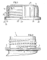
- the screw cap according to the invention comprises a cap, generally designated 10, wherein a sealing cone 11 is formed on the inner surface of the upper horizontal end wall of the cap 10 concentrically with its central longitudinal axis, which sealingly into the mouth of the shown in Fig. 2 Neck of a bottle 1 can intervene.
- the cap edge 12 extends essentially vertically downward with an internal thread 15 formed on its inner surface, according to which an external thread on the neck of the bottle 1, not shown in more detail Fig. 2 corresponds to the same angular distance from each other along the outer circumferential surface of the cap rim 12 vertically extending handle lugs 14 are formed, which should facilitate screwing the cap 10 on and off the neck of the bottle 1.
- a collar 20 extends essentially horizontally or perpendicularly to the central longitudinal axis of the closure cap 10, and an annular web 21 is formed on the outer circumferential edge thereof projecting downward.
- the ring web 21 has the task of covering the locking teeth 23 formed on the collar 20 from the outside, so that no manipulations can be carried out on them from the outside.
- the ratchet teeth 23 are preferably formed on resilient tongues 23 'and extend downward parallel therefrom at a distance from the ring web 21, so that the ratchet teeth 23 can make an up and down movement.
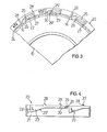
- the resilient tongues 23 ' preferably lie in the plane of the horizontal collar 20 and are formed according to FIG.
- the collar 20 is further connected to the outer circumferential surface of the cap edge 12 via a plurality of circumferentially distributed shear webs 27, 29, the shear webs 27, 29 forming the annular gap 24 between the collar 20 and Bridge the edge of the cap i2 and are dimensioned such that they tear off the collar 20 and the closure cap 10 at certain different relative rotations.
- the shear webs are divided into at least two groups.
- the shear webs 27 of the first group have a preferably frustoconical design and a length which essentially corresponds only to the width of the annular gap 24, wherein they are connected in an approximately punctiform manner on the outer circumference of the cap edge 12.
- the shear webs 29 of the second group have such an extension length between their shaping points on the collar 20 and on the outer peripheral surface of the cap rim 12 that they result in a relative rotation between the collar 20 and Cap 10 can participate in a larger angular range than the shear webs 27 without tearing by giving in laterally. Only after the said angular range has been exceeded do the shear rods 29 of the second group also tear off at their connection points on the cap edge 12, so that the closure cap 10 now finally comes free from the collar 20.
- the separation of the collar 20 and the closure cap 10 thus takes place according to the invention in at least two steps, by first tearing off only the short shear webs 27 of the first group when an initial torque is applied to the closure cap and then also shearing the shear webs 29 of the second group from when further torque is applied the cap are separated.
- Preferential the shear webs 29 are dimensioned such that the torque required for their shearing is approximately the same or only slightly greater than the torque which leads to the shearing of the shear webs 27 of the first group.
- Each shear web 29 of the second group preferably has a conical shape tapering in the direction of the cap edge 12, in that at least one side edge 29 "of the shear web has an oblique course, while the opposite other side edge 29 'can extend perpendicular to the cap edge 12.
- the angle of inclination the inclined side edge 29 " is preferably matched to the angle of inclination of an inclined surface 30 formed in the collar 20 in such a way that the shear web 29 is essentially flush with the inclined surface 30 relative to the collar 20 at a specific angular rotation of the closure cap 10.
- the inclined surface 30 therefore limits the path within which each shear web 29 can laterally deform or bend without tearing off from the cap edge 12.
- each inclined surface 30 preferably represents an imaginary extension in the unscrewing direction of the outer edge of the cutout 25 which extends in the circumferential direction and faces away from the cap edge 12 and which is on the inner The peripheral edge of the collar 20 ends.
- the shear web 29 is integrally formed at the transition point between said edge and inclined surface 30, so that it lies at a close distance from the free end of the resilient tongue 23 'in question.
- the shear webs 27 of the first group and the shear webs 29 of the second group along the circumference of the collar 20 should be such that a respective shear web 29 of the second group lies between an adjacent pair of shear webs 27 of the first group.
- the angular rotation of the closure cap 10 relative to the collar 20 required for shearing off the shear webs 27 of the first group can be e.g. 5 °
- an angular rotation of e.g. 10 to 15 ° is necessary.
- the inclined surface 30 can be at an angle of approximately 45 ° to a vertical plane which extends through the center of the closure cap and parallel to the one vertical side edge 29 'of the relevant shear web 29.
- At least the shear webs 27 of the first group are assigned pressure-collecting segments 28 which, according to FIG. 4, are formed on the top of the collar 20 and are preferably nose-shaped and have a trapezoidal cross-section.
- These D ructicianfangsemente 28 form at their the cap 10 ends facing abutment surfaces which come into contact with the outer surface of the closure cap, when, for example, to act for the transportation of the screw or unload the fasteners from the injection mold to the collar 20 lateral compressive forces without the 28 optionally cause provision of the pressure collecting segments that the collar appending edge moved and the free end of the collar K 12 characterized prematurely 20 is separated from the closure cap 10 degrees.
- pressure collecting segments 28 are not only cherstege in the range of S 27 of the first group but also at intermediate points of the collar 20 is provided. Furthermore, the pressure-collecting segments 28 stiffen the collar 20 with respect to a bend in the direction of the central longitudinal axis of the screw closure.
- the screw cap according to the invention When the screw cap according to the invention is used, it is screwed onto the neck of a bottle-like container, preferably a wide-neck bottle, by hand or by machine, the locking teeth 23 on the collar 20 in contact with the correspondingly designed locking teeth formed on the container neck during the screwing-on movement 3 come, which, like the ratchet teeth 23, are provided with ramp surfaces 3 "and vertical latching surfaces 3 '.
- the ramp surfaces 23" of the ratchet teeth 23 can slide on the ramp surfaces 3 "of the latching teeth 3, the ratchet teeth 23 being due to their Dodge the resilient formation on the collar 20.
Landscapes
- Engineering & Computer Science (AREA)
- Mechanical Engineering (AREA)
- Closures For Containers (AREA)
Priority Applications (1)
| Application Number | Priority Date | Filing Date | Title |
|---|---|---|---|
| AT80101287T ATE1891T1 (de) | 1979-03-15 | 1980-03-13 | Schraubverschlusskappe fuer flaschenartige behaelter. |
Applications Claiming Priority (2)
| Application Number | Priority Date | Filing Date | Title |
|---|---|---|---|
| DE2910178A DE2910178C2 (de) | 1979-03-15 | 1979-03-15 | Originalitäts-Schraubverschluß für Flaschen u.dgl |
| DE2910178 | 1979-03-15 |
Publications (2)
| Publication Number | Publication Date |
|---|---|
| EP0016419A1 true EP0016419A1 (fr) | 1980-10-01 |
| EP0016419B1 EP0016419B1 (fr) | 1982-12-01 |
Family
ID=6065470
Family Applications (1)
| Application Number | Title | Priority Date | Filing Date |
|---|---|---|---|
| EP80101287A Expired EP0016419B1 (fr) | 1979-03-15 | 1980-03-13 | Capsule à vis pour récipients du type bouteille |
Country Status (5)
| Country | Link |
|---|---|
| US (1) | US4326639A (fr) |
| EP (1) | EP0016419B1 (fr) |
| AT (1) | ATE1891T1 (fr) |
| CA (1) | CA1137924A (fr) |
| DE (2) | DE2910178C2 (fr) |
Cited By (2)
| Publication number | Priority date | Publication date | Assignee | Title |
|---|---|---|---|---|
| GB2136408A (en) * | 1983-03-02 | 1984-09-19 | Massmould Holdings | Push-on screw-off closure and container |
| US7616985B2 (en) | 2002-07-16 | 2009-11-10 | Xenogen Corporation | Method and apparatus for 3-D imaging of internal light sources |
Families Citing this family (30)
| Publication number | Priority date | Publication date | Assignee | Title |
|---|---|---|---|---|
| US4393978A (en) * | 1980-08-29 | 1983-07-19 | Kessler Products Co., Inc. | Reusable container closure cap |
| DE3512129A1 (de) * | 1985-04-03 | 1986-10-16 | Georg Menshen & Co Kg, 5950 Finnentrop | Originalitaetsverschluss fuer behaelter u.dgl. |
| US4785963A (en) * | 1988-01-11 | 1988-11-22 | Rieke Corporation | Tamper-evident buttress plug closure |
| FR2655953B1 (fr) * | 1989-12-15 | 1992-02-21 | Cebal | Perfectionnement au bouchage de recipients avec capsule de bouchage a vis et a bande de garantie arrachable. |
| US5273173A (en) * | 1990-02-05 | 1993-12-28 | Lynes Holding S.A. | Screw top |
| AU5345296A (en) * | 1996-05-06 | 1997-11-26 | Neopac Ag | Screw cap |
| US5967351A (en) * | 1997-07-10 | 1999-10-19 | Phoenix Closures, Inc. | Tamper-indicating closure with tapered connectors |
| US6003701A (en) * | 1998-02-04 | 1999-12-21 | Hidding; Walter E. | Tamper resistant bottle cap and neck |
| US6253942B1 (en) | 1998-04-30 | 2001-07-03 | Richard I. Elias | Easy opening, screw cap for threaded opening type containers |
| US6425480B1 (en) | 1999-09-27 | 2002-07-30 | Sparks International, Inc. | Mobile-dining mealholder with bottle-supported plate-lid |
| IE20000110A1 (en) * | 2000-02-07 | 2001-08-22 | Loctite R & D Ltd | Applicator, Applicator Cap and a Container Having an Applicator Cap |
| US7637384B2 (en) * | 2002-08-09 | 2009-12-29 | Crown Packaging Technology, Inc. | Tamper evident closure with locking band and container therefor |
| US20040045925A1 (en) * | 2002-09-11 | 2004-03-11 | Seidita Thomas M. | Tamper evident closure with locking band |
| US7527160B2 (en) * | 2003-10-09 | 2009-05-05 | Rexam Prescription Products Inc. | Closure having user-modifiable functionality |
| US20050167389A1 (en) * | 2004-02-04 | 2005-08-04 | Price Michael L. | Closure with improved resistance to deformation during opening |
| GB0503623D0 (en) * | 2005-02-22 | 2005-03-30 | Camlab Ltd | Secure sample collection |
| DE102005019393A1 (de) * | 2005-04-25 | 2006-10-26 | Basell Polyolefine Gmbh | Polyethylenformmassen für Spritzgussanwendungen |
| US20070034590A1 (en) * | 2005-08-04 | 2007-02-15 | Hidding Douglas J | Bottle with retained ring finish feature |
| ES2322750B1 (es) * | 2009-02-10 | 2010-07-15 | Francisco Santi Soriano Romero | Dispositivo para el control de fugas de un endoscopio. |
| US9016489B2 (en) * | 2010-06-30 | 2015-04-28 | Amcor Limited | Circumferential reinforcing groove for container finish |
| US9790005B2 (en) * | 2010-10-15 | 2017-10-17 | Closure Systems International Inc. | Plastic closure with enhanced performance |
| PE20170005A1 (es) | 2014-02-14 | 2017-03-04 | Closure Systems Int Inc | Cierre a prueba de manipulaciones mejorado |
| US9857343B2 (en) * | 2015-01-30 | 2018-01-02 | Ngk Spark Plug Co., Ltd. | Gas sensor with a ribbed protective cover |
| USD895925S1 (en) | 2018-07-31 | 2020-09-08 | Wieser Company LLC | Burial urn vault lid |
| WO2021063669A1 (fr) | 2019-09-30 | 2021-04-08 | Tetra Laval Holdings & Finance S.A. | Ensemble de fermeture pour un contenant et contenant comportant un tel système de fermeture |
| JP7688630B2 (ja) | 2019-10-07 | 2025-06-04 | クロージャー・システムズ・インターナショナル・インコーポレーテッド | フリップトップ式クロージャ |
| USD1063613S1 (en) | 2020-09-28 | 2025-02-25 | Closure Systems International Inc. | Closure with tamper-evident band |
| USD1063612S1 (en) | 2020-09-28 | 2025-02-25 | Closure Systems International Inc. | Closure with tamper-evident band |
| USD996968S1 (en) | 2021-05-17 | 2023-08-29 | Closure Systems International Inc. | Closure |
| USD996967S1 (en) | 2021-05-17 | 2023-08-29 | Closure Systems International Inc. | Closure |
Citations (5)
| Publication number | Priority date | Publication date | Assignee | Title |
|---|---|---|---|---|
| US3747793A (en) * | 1970-02-11 | 1973-07-24 | V Wassilieff | Safety closures for containers |
| FR2173757A2 (fr) * | 1972-03-01 | 1973-10-12 | Lancesseur Francois | |
| DE2243220A1 (de) * | 1972-09-01 | 1974-03-21 | Menshen Georg & Co Kg | Flaschenverschluss |
| FR2298255A7 (fr) * | 1975-01-20 | 1976-08-13 | Astra Plastique | Perfectionnements aux dispositifs de bouchage du type inviolable |
| DE2704461A1 (de) * | 1977-02-03 | 1978-08-10 | Hans Heinlein | Verschlusskappe mit originalitaetssicherung |
Family Cites Families (4)
| Publication number | Priority date | Publication date | Assignee | Title |
|---|---|---|---|---|
| FR1373744A (fr) | 1963-08-08 | 1964-10-02 | Trefimetaux | Capsule de bouchage à vis |
| FR1436645A (fr) | 1965-03-01 | 1966-04-29 | Bouchage Mecanique | Capsule de bouchage inviolable |
| US3463341A (en) * | 1967-12-18 | 1969-08-26 | Roehr Metals & Plastics Co | Tamper-indicating closure |
| US4062466A (en) * | 1976-10-07 | 1977-12-13 | Dairy Cap Corporation | Tamper-proof closure cap with self-removing ring |
-
1979
- 1979-03-15 DE DE2910178A patent/DE2910178C2/de not_active Expired
-
1980
- 1980-03-13 DE DE8080101287T patent/DE3061186D1/de not_active Expired
- 1980-03-13 EP EP80101287A patent/EP0016419B1/fr not_active Expired
- 1980-03-13 US US06/130,071 patent/US4326639A/en not_active Expired - Lifetime
- 1980-03-13 AT AT80101287T patent/ATE1891T1/de active
- 1980-03-14 CA CA000347734A patent/CA1137924A/fr not_active Expired
Patent Citations (5)
| Publication number | Priority date | Publication date | Assignee | Title |
|---|---|---|---|---|
| US3747793A (en) * | 1970-02-11 | 1973-07-24 | V Wassilieff | Safety closures for containers |
| FR2173757A2 (fr) * | 1972-03-01 | 1973-10-12 | Lancesseur Francois | |
| DE2243220A1 (de) * | 1972-09-01 | 1974-03-21 | Menshen Georg & Co Kg | Flaschenverschluss |
| FR2298255A7 (fr) * | 1975-01-20 | 1976-08-13 | Astra Plastique | Perfectionnements aux dispositifs de bouchage du type inviolable |
| DE2704461A1 (de) * | 1977-02-03 | 1978-08-10 | Hans Heinlein | Verschlusskappe mit originalitaetssicherung |
Cited By (2)
| Publication number | Priority date | Publication date | Assignee | Title |
|---|---|---|---|---|
| GB2136408A (en) * | 1983-03-02 | 1984-09-19 | Massmould Holdings | Push-on screw-off closure and container |
| US7616985B2 (en) | 2002-07-16 | 2009-11-10 | Xenogen Corporation | Method and apparatus for 3-D imaging of internal light sources |
Also Published As
| Publication number | Publication date |
|---|---|
| CA1137924A (fr) | 1982-12-21 |
| US4326639A (en) | 1982-04-27 |
| ATE1891T1 (de) | 1982-12-15 |
| DE2910178C2 (de) | 1981-02-26 |
| DE3061186D1 (en) | 1983-01-05 |
| EP0016419B1 (fr) | 1982-12-01 |
| DE2910178B1 (de) | 1980-06-26 |
Similar Documents
| Publication | Publication Date | Title |
|---|---|---|
| EP0016419B1 (fr) | Capsule à vis pour récipients du type bouteille | |
| DE69311372T2 (de) | Zusatzeinrichtung zum verschliessen von dosen für getränke o.dgl. | |
| EP0810952B1 (fr) | Bouchon de fermeture a bande de retenue | |
| DE69703425T2 (de) | VERSCHLUSSVORRICHTUNG UND BEHäLTER | |
| EP0086970B1 (fr) | Construction et procédé de montage d'un capuchon ainsi que capuchon pour un col de récipient muni d'un pas de vis ou d'un bourrelet | |
| EP0154603B1 (fr) | Capsule de bouchage en matière plastique | |
| EP0593396B1 (fr) | Fermeture de garantie en matière plastique | |
| DE69714827T2 (de) | Schraub-/Schnappverschluss und Behälterhals | |
| EP0103050B1 (fr) | Capuchon de fermeture pour bouteille muni d'un élément de garantie | |
| EP0137352A2 (fr) | Fermeture de garantie en matière plastique | |
| EP0281514B2 (fr) | Capsule de fermeture à bande de garantie | |
| DE3621575A1 (de) | Behaelter mit originalitaetsverschluss | |
| DE69004936T2 (de) | Ein Originalitätsverschluss für Spiritousenflaschen und dergleichen. | |
| DE2753080C2 (de) | Verschlußkappe mit Originalitätssicherung | |
| EP2601112B1 (fr) | Fermeture filetee munie d'une bande flexible | |
| EP0099332A2 (fr) | Capuchon de fermeture pour récipients | |
| WO2007031162A1 (fr) | Fermeture a vis inviolable destinee a des recipients et des bouteilles, en particulier des bouteilles en plastique | |
| CH647731A5 (de) | Flasche mit schraubverschluss und originalitaetssicherung. | |
| DE69818671T2 (de) | Kunststoff-schraubverschlusskappe mit originalitätsband | |
| EP0589254B1 (fr) | Capuchon inviolable | |
| EP1077883B1 (fr) | Combinaison d'un capuchon et d'un goulot filete de bouteille | |
| EP0457107B1 (fr) | Capuchon de fermeture pour flacons d'infusion ou de transfusion | |
| EP0343102B1 (fr) | Capuchon en matière plastique | |
| DE3108518C2 (fr) | ||
| DE4305138A1 (en) | Safety closure for bottles etc.with cap and safety ring with break line - has recesses between sectors formed around flanged lower edge of safety ring |
Legal Events
| Date | Code | Title | Description |
|---|---|---|---|
| PUAI | Public reference made under article 153(3) epc to a published international application that has entered the european phase |
Free format text: ORIGINAL CODE: 0009012 |
|
| AK | Designated contracting states |
Designated state(s): AT BE CH DE FR GB IT LU NL SE |
|
| 17P | Request for examination filed |
Effective date: 19801128 |
|
| ITF | It: translation for a ep patent filed | ||
| GRAA | (expected) grant |
Free format text: ORIGINAL CODE: 0009210 |
|
| AK | Designated contracting states |
Designated state(s): AT BE CH DE FR GB IT LU NL SE |
|
| REF | Corresponds to: |
Ref document number: 1891 Country of ref document: AT Date of ref document: 19821215 Kind code of ref document: T |
|
| REF | Corresponds to: |
Ref document number: 3061186 Country of ref document: DE Date of ref document: 19830105 |
|
| ET | Fr: translation filed | ||
| PG25 | Lapsed in a contracting state [announced via postgrant information from national office to epo] |
Ref country code: LU Free format text: LAPSE BECAUSE OF NON-PAYMENT OF DUE FEES Effective date: 19830331 |
|
| REG | Reference to a national code |
Ref country code: CH Ref legal event code: PUE Owner name: GEORG MENSHEN & CO. KG |
|
| PGFP | Annual fee paid to national office [announced via postgrant information from national office to epo] |
Ref country code: LU Payment date: 19900223 Year of fee payment: 11 |
|
| REG | Reference to a national code |
Ref country code: GB Ref legal event code: 732 |
|
| NLS | Nl: assignments of ep-patents |
Owner name: GEORG MENSHEN GMBH & CO. KG TE FINNENTROP, BONDSRE |
|
| NLT1 | Nl: modifications of names registered in virtue of documents presented to the patent office pursuant to art. 16 a, paragraph 1 |
Owner name: RIEDEL-DE HAEN AKTIENGESELLSCHAFT TE SEELZE EN GEO |
|
| ITTA | It: last paid annual fee | ||
| PGFP | Annual fee paid to national office [announced via postgrant information from national office to epo] |
Ref country code: SE Payment date: 19930210 Year of fee payment: 14 |
|
| PGFP | Annual fee paid to national office [announced via postgrant information from national office to epo] |
Ref country code: GB Payment date: 19930302 Year of fee payment: 14 |
|
| PGFP | Annual fee paid to national office [announced via postgrant information from national office to epo] |
Ref country code: AT Payment date: 19930311 Year of fee payment: 14 |
|
| PGFP | Annual fee paid to national office [announced via postgrant information from national office to epo] |
Ref country code: NL Payment date: 19930331 Year of fee payment: 14 |
|
| PGFP | Annual fee paid to national office [announced via postgrant information from national office to epo] |
Ref country code: CH Payment date: 19930405 Year of fee payment: 14 |
|
| PG25 | Lapsed in a contracting state [announced via postgrant information from national office to epo] |
Ref country code: GB Effective date: 19940313 Ref country code: AT Effective date: 19940313 |
|
| PG25 | Lapsed in a contracting state [announced via postgrant information from national office to epo] |
Ref country code: SE Free format text: LAPSE BECAUSE OF NON-PAYMENT OF DUE FEES Effective date: 19940314 |
|
| PG25 | Lapsed in a contracting state [announced via postgrant information from national office to epo] |
Ref country code: CH Effective date: 19940331 |
|
| PG25 | Lapsed in a contracting state [announced via postgrant information from national office to epo] |
Ref country code: NL Effective date: 19941001 |
|
| GBPC | Gb: european patent ceased through non-payment of renewal fee |
Effective date: 19940313 |
|
| NLV4 | Nl: lapsed or anulled due to non-payment of the annual fee | ||
| REG | Reference to a national code |
Ref country code: CH Ref legal event code: PL |
|
| EUG | Se: european patent has lapsed |
Ref document number: 80101287.3 Effective date: 19941010 |
|
| PGFP | Annual fee paid to national office [announced via postgrant information from national office to epo] |
Ref country code: FR Payment date: 19990302 Year of fee payment: 20 |
|
| PGFP | Annual fee paid to national office [announced via postgrant information from national office to epo] |
Ref country code: DE Payment date: 19990330 Year of fee payment: 20 |
|
| PGFP | Annual fee paid to national office [announced via postgrant information from national office to epo] |
Ref country code: BE Payment date: 19990416 Year of fee payment: 20 |
|
| BE20 | Be: patent expired |
Free format text: 20000313 *RIEDEL-DE HAEN A.G.;*MENSHEN GEORG + CO. K.G. |
|
| PLBE | No opposition filed within time limit |
Free format text: ORIGINAL CODE: 0009261 |
|
| STAA | Information on the status of an ep patent application or granted ep patent |
Free format text: STATUS: NO OPPOSITION FILED WITHIN TIME LIMIT |