EP0016524A2 - Linsenrand-Schleifmaschinen - Google Patents
Linsenrand-Schleifmaschinen Download PDFInfo
- Publication number
- EP0016524A2 EP0016524A2 EP80300382A EP80300382A EP0016524A2 EP 0016524 A2 EP0016524 A2 EP 0016524A2 EP 80300382 A EP80300382 A EP 80300382A EP 80300382 A EP80300382 A EP 80300382A EP 0016524 A2 EP0016524 A2 EP 0016524A2
- Authority
- EP
- European Patent Office
- Prior art keywords
- frame
- lens
- lens edge
- grinding machine
- edge grinding
- Prior art date
- Legal status (The legal status is an assumption and is not a legal conclusion. Google has not performed a legal analysis and makes no representation as to the accuracy of the status listed.)
- Withdrawn
Links
- 238000000227 grinding Methods 0.000 title claims abstract description 112
- 238000006073 displacement reaction Methods 0.000 claims description 23
- 230000000694 effects Effects 0.000 claims description 5
- 230000003028 elevating effect Effects 0.000 claims description 2
- 230000005294 ferromagnetic effect Effects 0.000 claims description 2
- 230000002093 peripheral effect Effects 0.000 description 12
- CWYNVVGOOAEACU-UHFFFAOYSA-N Fe2+ Chemical compound [Fe+2] CWYNVVGOOAEACU-UHFFFAOYSA-N 0.000 description 4
- 230000007547 defect Effects 0.000 description 3
- 238000013459 approach Methods 0.000 description 2
- 238000005304 joining Methods 0.000 description 2
- 239000000463 material Substances 0.000 description 2
- 238000000034 method Methods 0.000 description 2
- 230000000712 assembly Effects 0.000 description 1
- 238000000429 assembly Methods 0.000 description 1
- 238000010924 continuous production Methods 0.000 description 1
- 230000002950 deficient Effects 0.000 description 1
- 230000005484 gravity Effects 0.000 description 1
- 230000005291 magnetic effect Effects 0.000 description 1
- 238000004519 manufacturing process Methods 0.000 description 1
- 239000002184 metal Substances 0.000 description 1
- 238000012986 modification Methods 0.000 description 1
- 230000004048 modification Effects 0.000 description 1
- 230000002250 progressing effect Effects 0.000 description 1
Images

Classifications
-
- B—PERFORMING OPERATIONS; TRANSPORTING
- B24—GRINDING; POLISHING
- B24B—MACHINES, DEVICES, OR PROCESSES FOR GRINDING OR POLISHING; DRESSING OR CONDITIONING OF ABRADING SURFACES; FEEDING OF GRINDING, POLISHING, OR LAPPING AGENTS
- B24B9/00—Machines or devices designed for grinding edges or bevels on work or for removing burrs; Accessories therefor
- B24B9/02—Machines or devices designed for grinding edges or bevels on work or for removing burrs; Accessories therefor characterised by a special design with respect to properties of materials specific to articles to be ground
- B24B9/06—Machines or devices designed for grinding edges or bevels on work or for removing burrs; Accessories therefor characterised by a special design with respect to properties of materials specific to articles to be ground of non-metallic inorganic material, e.g. stone, ceramics, porcelain
- B24B9/08—Machines or devices designed for grinding edges or bevels on work or for removing burrs; Accessories therefor characterised by a special design with respect to properties of materials specific to articles to be ground of non-metallic inorganic material, e.g. stone, ceramics, porcelain of glass
- B24B9/14—Machines or devices designed for grinding edges or bevels on work or for removing burrs; Accessories therefor characterised by a special design with respect to properties of materials specific to articles to be ground of non-metallic inorganic material, e.g. stone, ceramics, porcelain of glass of optical work, e.g. lenses, prisms
Definitions
- This invention relates to lens edge grinding machines and more particularly to so-called "multi-wheel” lens edge grinding machines for grinding the edges of spectacle and the like lenses.
- Multi-wheel lens edge grinding machines are well known in the art and conventionally comprise a base housing, a frame mounted atop the base and pivotable about a horizontal axis, a driven shaft supporting a plurality of grinding wheels within the base to present the upper regions of the grinding wheels through an opening in an upper surface of the base housing, and co-axially aligned lens supports presented by the frame and intended to engage the major faces of a lens therebetween.
- the pivotal axis of the frame, the axis of said driven shaft, and the common axis of the lens supports are all parallel, the frame is arranged for displacement in the direction of its pivotal axis to allow a supported lens to be engaged selectively with any one of said grinding wheels, and means are provided for rotating the lens supports in accordance with a predetermined programme.
- the first grinding wheel is a plain cylindrical wheel intended to rough grind the lens to a desired peripheral configuration and the second grinding wheel is intended to impart the desired peripheral cross-section on the lens.
- the second grinding wheel is intended to impart the desired peripheral cross-section on the lens.
- one of the lens edge supports conveniently carries a cam, engageable with an anvil individually set to each of the grinding wheels, and the cam is rotated with the lens thus to angularly adjust the frame relative to the base during grinding so that the desired peripheral configuration is imparted to the lens.
- the frame is advantageously allowed to "float" transversely to permit ' that part of the lens edge in contact with the grinding wheel to "self locate” with respect to the wheel, other "second” grinding operations require a more positive guide to effect displacement of the frame relative to the base.
- a further danger in utilizing a stop means which creates permanent forces between the frame and the base is that, with time, wear on the stop members can so displace the frame relative to the grinding wheels that the machine becomes defective and, in a continuous production process, a large number of lenses can be ruined before the defect is observed.
- a multi-wheel lens edge grinding machine comprising a base housing, a plurality of grinding wheels on a common shaft supported by said housing a motor for rotating said grinding wheels in unison and a lens support frame pivotally attached to the base housing via a pivot shaft parallelto the common shaft of said grinding wheels'to permit the frame to displace between a low position, in which a lens supported by said frame is engageable by one or other of said grinding wheels and a high position, in which a lens supported by said frame is elevated to a position clear of all said grinding wheels, said frame further being displaceable in the direction of its pivot shaft to permit a lens supported by said frame to be selectively engageable with each of said grinding wheels, characterised by a cam plate within said base housing adapted to positively engage an element of said frame when said frame is in an elevated position, and a drive arrangement for positively displacing said cam plate in the general direction of the said pivot shaft,
- the frame is positively engaged for mutual transverse displacement with the cam plate when the frame is elevated from the grinding position.
- the cam plate includes a cam opening therethrough and said frame element always projects into said opening.
- the opening preferably includes a slot-like part into which the frame element projects when the frame is elevated, a part wider than said slot-like part and into which the frame element projects when the frame is lowered, and guide surfaces for guiding the frame element from said wider part of said opening into said slot as the frame is elevating.
- said cam plate is displaced by an electric motor,actuable only when the frame is in an elevated position with respect to the base housing.,and conveniently said electric motor drives the cam plate via a worm arrangement.
- a circuit for said motor includes a micro switch adapted to be actuated to close the motor circuit only when the frame is in its elevated position.
- a circuit for said motor includes two micro switches, actuation of either one of which opens the motor circuit, one said micro switch being adapted to be actuated when.the frame displaces to one desired extreme transverse position and the other said micro switch being adapted to be actuated when the frame displaces to its other desired extreme transverse position.
- the machine includes a spring-loaded pivoted lever arranged to be angularly displaced against its spring loading by an element of the frame to define one extreme position for the frame in one direction of the axis of the pivot shaft, said lever when so displaced serving to actuate one of said micro switches to open the motor circuit thus to terminate displacement of the cam plate and frame.
- the spring acting on said spring loaded lever has such rating that said spring returns said lever to displace said frame from its said extreme position to a desired position, as said frame lowers and said frame element loses its positive engagement with said cam plate.
- both micro switches are actuated by spring loaded pivoted levers and said levers limit the displacement of the frame in the directions of the axis of the pivot shaft for the frame.
- the spring loading for each lever comprises the return spring of the actuating member of the micro switch associated with that lever.
- one of said spring loaded pivoted levers comprises a cam lever adapted, when engaged by the pin element presented by the frame, to effect a controlled displacement of the frame in the direction of the pivotal axis of the frame in dependence upon change in the angular position of the frame relative to the base housing.
- the machine includes a permanent magnet for retaining the frame against a stop substantially fixed with respect to the base housing and preferably the permanent magnet is mounted on the frame and is co-operable with a ferro-magnetic stop member attached to the base housing.
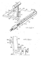
- the multi-wheel lens edge grinding machine illustrated in Fig. 1 comprises a housing 11 presenting a substantially flat upper surface 12 with two parallel brackets 13 and 14 upstanding from the rear edge region thereof.
- a shaft 15, rotatably and axially displaceable in bearings presented by brackets 13 and 14, has a frame 16 secured thereto and frame 16 co-axially supports rotatable lens supports 17 and 18 parallel to the axis of shaft 15.
- the lens support 18 is rotatable by a motor 19 within frame 16 and support 18 extends outwardly of the frame 16 to support a disc cam 20, the periphery of which is selectively engageable with three anvils 21, 22 or 23.
- the housing 11 has a rectangular opening 12a in surface 12 and the upper regions of three grinding wheels 24, 25 and 26, in side by side relationship, are exposed through opening 12a.
- the grinding wheels 24, 25 and 26 are mounted on a shaft 27, rotatably supported within housing 11 and driven by a motor 28 within housing 11.
- the device described thus far conforms with conventional multi-wheel lens edge grinding machines and operates as follows:-With the frame 16 elevated (rotated clockwise when viewed in the direction of the arrow "A" in Fig. 1) the lens supports 17 and 18 are separated to permit a lens 29 to be introduced therebetween and the lens supports 17 and 18 are then closed on the major faces of the lens 29 to support lens 29 firmly therebetween.
- a cam 20, conforming to the desired peripheral shape for the lens 29, is secured on the lens support 18, the motor 28 is started to rotate shaft 27 and grinding wheels 24, 25 and 26 and, when the grinding wheels 24, 25 and 26 are rotating at operational speed and with the frame 16 transversely located so that the periphery of lens 29 lies in the plane of grinding wheel 26 (the first grinding wheel) frame 16 is lowered, by anti-clockwise rotation when viewed in the direction of the arrow "A" to initiate the first grinding operation.
- the grinding wheel 26 will be effective upon the engaged peripheral edge of lens 29 as and until the cam 20 engages the first anvil 23, which is set to the periphery of grinding wheel 26.
- the motor 19 is started so that lens support 18, with cam 20 thereon, lens 29 and lens support 17 are rotated, at slow speed, and conveniently with a stepping motion so that the grinding wheel 26 generally reduces the periphery of lens 29 to conform with the periphery of cam 20 in a single revolution of lens 29.
- the motor 19 continues to rotate lens 29 to perform a second rotation which, in effect, rough finishes lens 29.
- the frame 16 is again elevated (rotated clockwise when viewed in the direction of arrow "A"), the frame 16 is transversely displaced (shaft 15 axially sliding in bearings 13 and 14) to locate the lens 29 in the plane of grinding wheel 25 or grinding wheel 24.
- Thegrinding wheels 24 and 25 will have differently shaped peripheral edges and, at this stage, it is left to the operator to select which periphery is to be ground on the lens.
- the frame 16 is again lowered (rotated anti-clockwise as viewed in the direction of arrow "A") until the periphery of lens 29 engages the grinding wheel and grinding is initiated, again the cam 20 will be aligned with an anvil 21 (if grinding wheel 24 is operational) or anvil 22 (if grinding wheel 25 is operational) and again motor 19 will rotate lens 29 through two complete revolutions to impart on the periphery of lens 29 the peripheral cross-section determined by the peripheral groove in the grinding wheel 24 or 25 operational on the lens.
- the frame 16 is again elevated to permit the lens supports 17 and 18 to be separated to allow the lens 29 to be removed therefrom.
- a cam plate 30 with an integral guide flange 31, is supported on a runway 32 within housing 11, the flange 31 locates in a substantially vertical slot 33 in runway 32 so that plate 30 always lies substantially horizontal.
- a drive shaft 34, secured to cam plate 30, has a worm 35 formed thereon and worm 35 passes through an electric motor 36 adapted, when actuated, to act on worm 35 to axially displace shaft 34, in a direction depending upon the direction of rotation of motor 36.
- the cam plate 30 includes a cam opening 37 therethrough defined by an edge 38, generally at right angles to the shaft 34, an edge 39 remote from the shaft 34 and generally parallel thereto,said edge 39 joining edge 38 with an edge 40 parallel to edge 38 but of shorter length than edge 38, an edge 41 extending from edge 40 towards edge 38 and at an angle in the region of 45° to both edges 40 and 39, an edge 42 extending from edge 41 towards shaft 34 and parallel to edge 38, and an edge 43 joining edge t 1 2 with edge 38 at that part of opening 37 closest to shaft 34.
- the shaft 15 presents a radial pin 44 which has a diameter slightly less than the distance between edges 38 and 42 and, when the frame 16 is displaced to elevate the lens supporting part away from the grinding wheels 24, 25 and 26, the pin 44 enters snugly into the slot defined by edges 38, 42 and 43.
- The. pin 44 has such length that when the frame is lowered to a grinding position the pin 44 locates in the wider part of the opening 37 defined between edge 38 and edges 40 and 41.
- the frame 16 . . is lowered to engage the lens 29 with grinding wheel 26 the pin 44 slides along edge 38 and out of the slot defined by edges 38, 42 and 40.
- the edge 38 prevents transverse displacement of frame 16 towards the left, as viewed in Fig. 2, but the cam offers no restriction to displacement of pin 44 away from edge 38 towards edge 40, whereby a degree of transverse "float" of the frame 16 is permitted by the cam 30.
- the pin 44 may be in any location between edges 38 and 40 but, if the pin 44 is displaced from edge 38, the progressing elevation of frame 16 causes pin 44 to engage the inclined guide edge 41 and further elevation of frame 16 is accompanied by transverse displacement of frame 16 as pin 44 slides along edge 41 until pin 44 is located to engage in the slot defined by edges 38, 42 and 43 when the elevation of the frame l6 can be completed.
- the motor 36 will be deactivated when the lens 29 lies in the plane of the desired second grinding wheel 24 or 25 and, as the frame 16 is then lowered to the grinding position, the pin 44 again rides out of the slot defined by edges 38, 42 and 43.
- a lens cam 45 with a cam surface 46, is pivotally attached by a pin 47 to a slide member 48, slidably disposed in a guide member 49 secured to surface 12.
- a screw member 50 passes through part of guide member 4.9 and through a bore in slide member 48 and screw member 50 is rotatable, but held against axial displacement, with respect to slide member 48 and is in threaded engagement with slide member 49 so that, by rotating the wheel 50a on screw 50, the slide member 48 is slidably displaced with respect to guide member 49 and, as will be seen from Fig. 1, the direction of displacement of member 48 in member 49 is parallel to the axis of shaft 15.
- a micro switch 51 is located between lens cam 45 and slide member 48, the actuator spring (not shown) of the switch 51 urges clockwise rotation of lens cam 45 about pin 47 (as viewed in Fig. 3) and an extension 48a of slide member 48 engages in a recess 45a in lens cam 45 to limit the angular displacement of lens cam 45.
- the micro switch 51 constitutes, when actuated, a cut-off for breaking the power circuit to motor 36.
- the operator will, after selecting which of the grinding wheels 24 or 25 is to be used to finish a lens, set the adjustment of slide member 48 to a predetermined mark identified with the selected grinding wheel.
- the return spring on the . micro switch 51 will maintain the lens cam in its most clockwise location (as viewed in Fig. 3) with the extension 48a engaged with the lowermost surface of recess 45a and, with the micro switch 51 so arranged, the power circuit to motor 36 is. completed, when the first grinding operation is completed, to displace cam plate 30 and frame 16 towards the second grinding position.
- a frame guide pin 52 projecting from the front of frame 16 and intended to co-operate with lens cam surface 46 during the second grinding operation, approaches lens cam 45 and eventually engages surface 46. Further displacement towards the left, under motor 36, causes lens cam 45 to be rotated anti-clockwise (as viewed in Fig. 3) about pin 47, such rotation causes micro switch 51 to be actuated and said switch actuation breaks the drive circuit to motor 36 to cause the transverse displacement to terminate.
- the upper part of the cam surface 46 is substantially vertical so that, when the frame guide pin 52 first engages cam surface 46 and displaces the lens cam 45 to actuate micro switch 51,the frame 16 can still be downwardly displaced, pin 52 sliding down cam surface h6, until the pin 44 is displaced out of the slot defined by edges 38, 42 and 43 and the frame 16 can move towards the right (pin 44 displacing away from edge 38).
- the return spring of micro switch 51 becomes effective to return lens cam 45 to its most clockwise rotation, this causes a small displacement of frame 16 towards the right (as viewed in Fig. 1) and, thereafter, the frame 16 is correctly located, with its guide pin 52 in engagement with cam surface 46, for the second grinding operation.
- the present invention overcomes this difficulty by providing a permanent magnet 52a as part of the frame guide pin 52, the magnet 52a has one end tapped to receive a screw 52b presented by a non-ferrous stub pin 52c secured to the frame 16, and as the lens cam 45 is made from a ferrous material the magnet 52a in direct engagement with surface 46 provides a uniform retaining force for all positions of pin 52 along surface 46.
- a base member 53 secured on surface 12, slidably retains a member 54-and, a screw 55, in threaded engagement with slideable member 54 and rotatable, but non-axially displaceable, with respect to base member 53, serves to adjust the position of slidable member 54 in the direction of the axis of shaft 15.
- An upright member 56 is pivotally attached to slidable member 54 and presents a limb 56a, engageable with the actuating member of a micro switch 57 and captive beneath an extension 54a of slidable member 54.
- the return spring (not shown) retains limb 56a against the undersurface of extension 54a and the micro switch, which is effective on the power circuit of motor 36 when operated,is closed.
- a frame pin 58 is aligned to engage the face of member 56 adjacent the frame and, as will be seen from Fig. 4, the said face, when the device is not affected by pin 58, is inclined to the vertical.
- the frame 16 may be given an enforced transverse displacement, as it oscillates, during the first grinding operation by providing a magnetic attraction between pin 58 and upright 56 and in the illustrated example, the pin 58 comprises a non-ferrous part 58a secured to frame 16 and a permanent magnet 58b supported on part 58a and said member 56 is made from a ferrous material.
- the transverse displacement of the frame 16 between its pre-set stops is automatically controlled by the micro switches 51 and 57 and it will be appreciated that the circuit for motor 36 will include means which prevent the motor circuit from closing to re-activate motor 36 when a micro switch 51 or 57 returns to its inoperative condition.
- Such a means may comprise a simple relay in the motor circuit.
- the circuit for motor 36 preferably includes a microswitch 59, engageable with pin l 1 4, and activated only when the frame is elevated to permit the circuit of motor 36 to be completed.
- the machine includes a hydraulic piston and cylinder arrangement 60 for raising and lowering the frame 16, said arrangement being controlled by a counter associated with shaft 18 to elevate frame 16 each time shaft 18 completes its two revolutions.
- the piston and cylinder arrangement 60 may also be arranged to lower frame 16 upon actuating of a "start" switch by the operator and by actuation of the microswitch 51 and, thereby, a fully automatic operation may be obtained.
- the switch 59 is again actuated as the frame reaches its elevated position and the motor 36 is operated, in reverse direction, to drive the cam plate 30 and the frame 16 back to the start position when, the micro switch 51 is operated, the "start" circuit is broken, and the ground lens can be removed.
Landscapes
- Engineering & Computer Science (AREA)
- Chemical & Material Sciences (AREA)
- Ceramic Engineering (AREA)
- Inorganic Chemistry (AREA)
- Mechanical Engineering (AREA)
- Grinding And Polishing Of Tertiary Curved Surfaces And Surfaces With Complex Shapes (AREA)
Applications Claiming Priority (2)
| Application Number | Priority Date | Filing Date | Title |
|---|---|---|---|
| GB7905308A GB2041800A (en) | 1979-02-15 | 1979-02-15 | Lens edge grinding machine |
| GB7905308 | 1979-02-15 |
Publications (2)
| Publication Number | Publication Date |
|---|---|
| EP0016524A2 true EP0016524A2 (de) | 1980-10-01 |
| EP0016524A3 EP0016524A3 (de) | 1980-10-29 |
Family
ID=10503210
Family Applications (1)
| Application Number | Title | Priority Date | Filing Date |
|---|---|---|---|
| EP80300382A Withdrawn EP0016524A3 (de) | 1979-02-15 | 1980-02-11 | Linsenrand-Schleifmaschinen |
Country Status (3)
| Country | Link |
|---|---|
| EP (1) | EP0016524A3 (de) |
| JP (1) | JPS55150958A (de) |
| GB (1) | GB2041800A (de) |
Families Citing this family (4)
| Publication number | Priority date | Publication date | Assignee | Title |
|---|---|---|---|---|
| JPS5843227B2 (ja) | 1980-02-13 | 1983-09-26 | 孝正 田窪 | 自動玉摺機 |
| US4394099A (en) * | 1981-01-22 | 1983-07-19 | Lemay Corporation | Plastic lens contour cutting machine |
| FR2562829B1 (fr) * | 1984-04-12 | 1986-06-13 | Briot Int | Dispositif de commande de relevage et de translation du chariot d'une machine a deborder et a biseauter les verres de lunettes |
| EP0257258A1 (de) * | 1986-08-28 | 1988-03-02 | Wernicke & Co. GmbH | Brillenglasrandschleifmaschine |
Family Cites Families (7)
| Publication number | Priority date | Publication date | Assignee | Title |
|---|---|---|---|---|
| US3332172A (en) * | 1964-11-16 | 1967-07-25 | A I T Machine Co Inc | Automatic edger |
| FR1510824A (fr) * | 1966-03-07 | 1968-01-26 | Perfectionnement apporté aux machines permettant de déborder, de biseauter et de rainurer les verres de lunettes | |
| DE1956327A1 (de) * | 1969-11-08 | 1971-08-12 | Kraus Felix Gunter | Steuervorrichtung fuer Brillenglasrand-Schleifmaschinen |
| GB1369912A (en) * | 1972-01-22 | 1974-10-09 | Rodway Optical Ind Ltd | Lens edge grinding machines |
| GB1420502A (en) * | 1973-05-07 | 1976-01-07 | Raphaels Ltd | Lens edging machine |
| GB1516936A (en) * | 1977-04-14 | 1978-07-05 | Raphaels Ltd | Adjustment means for optical lens edge grinding machines |
| US4176498A (en) * | 1978-02-21 | 1979-12-04 | Ait Industries, Inc. | Apparatus for edging lenses |
-
1979
- 1979-02-15 GB GB7905308A patent/GB2041800A/en not_active Withdrawn
-
1980
- 1980-02-11 EP EP80300382A patent/EP0016524A3/de not_active Withdrawn
- 1980-02-15 JP JP1768480A patent/JPS55150958A/ja active Pending
Also Published As
| Publication number | Publication date |
|---|---|
| GB2041800A (en) | 1980-09-17 |
| JPS55150958A (en) | 1980-11-25 |
| EP0016524A3 (de) | 1980-10-29 |
Similar Documents
| Publication | Publication Date | Title |
|---|---|---|
| US3978764A (en) | Automatic key duplicating apparatus | |
| US3894361A (en) | Lens grinding machine | |
| US3555739A (en) | Machine for shaping, sizing and finishing the edge of a lens blank | |
| US3274736A (en) | Edge tooling apparatus | |
| US2321383A (en) | Contour forming apparatus | |
| EP0016524A2 (de) | Linsenrand-Schleifmaschinen | |
| CA2096763A1 (en) | Skate sharpening machine | |
| US5036624A (en) | Notch grinder | |
| EP0274276A2 (de) | Maschine und Verfahren zur Randbearbeitung von Linsen | |
| US4870784A (en) | Lens edging machine and method | |
| US2612734A (en) | Apparatus for grinding the bevel edge of spectacle and other lenses | |
| EP1138436B1 (de) | Linsenrand-Schleifmaschine | |
| JPH1190807A (ja) | 容器等の倣い研摩装置 | |
| EP1352707B1 (de) | Vorrichtung zur Bearbeitung eines Brillenglases | |
| US3461619A (en) | Edge-grinding machine for lenses | |
| US3315415A (en) | Bevel edging device | |
| US5383759A (en) | Low particle wafer automatic flat aligner | |
| US3213715A (en) | Indexing mechanism | |
| US4003165A (en) | Machine for beveling lenses | |
| US4928439A (en) | Lens edging machine and method | |
| US3942287A (en) | Contour grinders | |
| JP3699351B2 (ja) | 板材端面研削装置 | |
| GB937178A (en) | A lapping machine | |
| US3568370A (en) | Lens cribber | |
| JPH0413077Y2 (de) |
Legal Events
| Date | Code | Title | Description |
|---|---|---|---|
| PUAI | Public reference made under article 153(3) epc to a published international application that has entered the european phase |
Free format text: ORIGINAL CODE: 0009012 |
|
| PUAL | Search report despatched |
Free format text: ORIGINAL CODE: 0009013 |
|
| AK | Designated contracting states |
Designated state(s): AT BE CH DE FR IT LU NL SE |
|
| AK | Designated contracting states |
Designated state(s): AT BE CH DE FR IT LU NL SE |
|
| STAA | Information on the status of an ep patent application or granted ep patent |
Free format text: STATUS: THE APPLICATION HAS BEEN WITHDRAWN |
|
| 18W | Application withdrawn |
Withdrawal date: 19810220 |
|
| RIN1 | Information on inventor provided before grant (corrected) |
Inventor name: BENNETT, BRIAN Inventor name: MOODY, BRYAN MALCOLM |