EP0016643B1 - Rotor et son montage sur l'arbre d'un compresseur à grande vitesse - Google Patents
Rotor et son montage sur l'arbre d'un compresseur à grande vitesse Download PDFInfo
- Publication number
- EP0016643B1 EP0016643B1 EP80300858A EP80300858A EP0016643B1 EP 0016643 B1 EP0016643 B1 EP 0016643B1 EP 80300858 A EP80300858 A EP 80300858A EP 80300858 A EP80300858 A EP 80300858A EP 0016643 B1 EP0016643 B1 EP 0016643B1
- Authority
- EP
- European Patent Office
- Prior art keywords
- impeller
- extremity
- shaft
- socket
- shaft assembly
- Prior art date
- Legal status (The legal status is an assumption and is not a legal conclusion. Google has not performed a legal analysis and makes no representation as to the accuracy of the status listed.)
- Expired
Links
- 230000006835 compression Effects 0.000 title 1
- 238000007906 compression Methods 0.000 title 1
- 239000000463 material Substances 0.000 claims description 11
- 229910000831 Steel Inorganic materials 0.000 claims description 3
- 239000010959 steel Substances 0.000 claims description 3
- 229910000838 Al alloy Inorganic materials 0.000 claims description 2
- 238000009434 installation Methods 0.000 description 3
- 238000007373 indentation Methods 0.000 description 2
- 229910001339 C alloy Inorganic materials 0.000 description 1
- 238000004378 air conditioning Methods 0.000 description 1
- 229910045601 alloy Inorganic materials 0.000 description 1
- 239000000956 alloy Substances 0.000 description 1
- XAGFODPZIPBFFR-UHFFFAOYSA-N aluminium Chemical compound [Al] XAGFODPZIPBFFR-UHFFFAOYSA-N 0.000 description 1
- 229910052782 aluminium Inorganic materials 0.000 description 1
- 230000000712 assembly Effects 0.000 description 1
- 238000000429 assembly Methods 0.000 description 1
- 238000005266 casting Methods 0.000 description 1
- 238000010276 construction Methods 0.000 description 1
- 238000006073 displacement reaction Methods 0.000 description 1
- 238000003754 machining Methods 0.000 description 1
- 230000013011 mating Effects 0.000 description 1
Images

Classifications
-
- G—PHYSICS
- G02—OPTICS
- G02B—OPTICAL ELEMENTS, SYSTEMS OR APPARATUS
- G02B6/00—Light guides; Structural details of arrangements comprising light guides and other optical elements, e.g. couplings
-
- F—MECHANICAL ENGINEERING; LIGHTING; HEATING; WEAPONS; BLASTING
- F16—ENGINEERING ELEMENTS AND UNITS; GENERAL MEASURES FOR PRODUCING AND MAINTAINING EFFECTIVE FUNCTIONING OF MACHINES OR INSTALLATIONS; THERMAL INSULATION IN GENERAL
- F16D—COUPLINGS FOR TRANSMITTING ROTATION; CLUTCHES; BRAKES
- F16D1/00—Couplings for rigidly connecting two coaxial shafts or other movable machine elements
- F16D1/06—Couplings for rigidly connecting two coaxial shafts or other movable machine elements for attachment of a member on a shaft or on a shaft-end
- F16D1/08—Couplings for rigidly connecting two coaxial shafts or other movable machine elements for attachment of a member on a shaft or on a shaft-end with clamping hub; with hub and longitudinal key
- F16D1/09—Couplings for rigidly connecting two coaxial shafts or other movable machine elements for attachment of a member on a shaft or on a shaft-end with clamping hub; with hub and longitudinal key with radial clamping due to axial loading of at least one pair of conical surfaces
- F16D1/092—Couplings for rigidly connecting two coaxial shafts or other movable machine elements for attachment of a member on a shaft or on a shaft-end with clamping hub; with hub and longitudinal key with radial clamping due to axial loading of at least one pair of conical surfaces the pair of conical mating surfaces being provided on the coupled hub and shaft
-
- C—CHEMISTRY; METALLURGY
- C03—GLASS; MINERAL OR SLAG WOOL
- C03B—MANUFACTURE, SHAPING, OR SUPPLEMENTARY PROCESSES
- C03B37/00—Manufacture or treatment of flakes, fibres, or filaments from softened glass, minerals, or slags
- C03B37/01—Manufacture of glass fibres or filaments
- C03B37/012—Manufacture of preforms for drawing fibres or filaments
- C03B37/014—Manufacture of preforms for drawing fibres or filaments made entirely or partially by chemical means, e.g. vapour phase deposition of bulk porous glass either by outside vapour deposition [OVD], or by outside vapour phase oxidation [OVPO] or by vapour axial deposition [VAD]
- C03B37/01413—Reactant delivery systems
-
- C—CHEMISTRY; METALLURGY
- C03—GLASS; MINERAL OR SLAG WOOL
- C03B—MANUFACTURE, SHAPING, OR SUPPLEMENTARY PROCESSES
- C03B37/00—Manufacture or treatment of flakes, fibres, or filaments from softened glass, minerals, or slags
- C03B37/01—Manufacture of glass fibres or filaments
- C03B37/012—Manufacture of preforms for drawing fibres or filaments
- C03B37/014—Manufacture of preforms for drawing fibres or filaments made entirely or partially by chemical means, e.g. vapour phase deposition of bulk porous glass either by outside vapour deposition [OVD], or by outside vapour phase oxidation [OVPO] or by vapour axial deposition [VAD]
- C03B37/01446—Thermal after-treatment of preforms, e.g. dehydrating, consolidating, sintering
-
- F—MECHANICAL ENGINEERING; LIGHTING; HEATING; WEAPONS; BLASTING
- F04—POSITIVE - DISPLACEMENT MACHINES FOR LIQUIDS; PUMPS FOR LIQUIDS OR ELASTIC FLUIDS
- F04D—NON-POSITIVE-DISPLACEMENT PUMPS
- F04D17/00—Radial-flow pumps, e.g. centrifugal pumps; Helico-centrifugal pumps
- F04D17/08—Centrifugal pumps
- F04D17/10—Centrifugal pumps for compressing or evacuating
-
- F—MECHANICAL ENGINEERING; LIGHTING; HEATING; WEAPONS; BLASTING
- F04—POSITIVE - DISPLACEMENT MACHINES FOR LIQUIDS; PUMPS FOR LIQUIDS OR ELASTIC FLUIDS
- F04D—NON-POSITIVE-DISPLACEMENT PUMPS
- F04D29/00—Details, component parts, or accessories
- F04D29/26—Rotors specially for elastic fluids
- F04D29/266—Rotors specially for elastic fluids mounting compressor rotors on shafts
-
- G—PHYSICS
- G02—OPTICS
- G02B—OPTICAL ELEMENTS, SYSTEMS OR APPARATUS
- G02B6/00—Light guides; Structural details of arrangements comprising light guides and other optical elements, e.g. couplings
- G02B6/02—Optical fibres with cladding with or without a coating
- G02B6/028—Optical fibres with cladding with or without a coating with core or cladding having graded refractive index
- G02B6/0281—Graded index region forming part of the central core segment, e.g. alpha profile, triangular, trapezoidal core
-
- G—PHYSICS
- G02—OPTICS
- G02B—OPTICAL ELEMENTS, SYSTEMS OR APPARATUS
- G02B6/00—Light guides; Structural details of arrangements comprising light guides and other optical elements, e.g. couplings
- G02B6/02—Optical fibres with cladding with or without a coating
- G02B6/036—Optical fibres with cladding with or without a coating core or cladding comprising multiple layers
- G02B6/03605—Highest refractive index not on central axis
- G02B6/03611—Highest index adjacent to central axis region, e.g. annular core, coaxial ring, centreline depression affecting waveguiding
-
- C—CHEMISTRY; METALLURGY
- C03—GLASS; MINERAL OR SLAG WOOL
- C03B—MANUFACTURE, SHAPING, OR SUPPLEMENTARY PROCESSES
- C03B2201/00—Type of glass produced
- C03B2201/02—Pure silica glass, e.g. pure fused quartz
-
- C—CHEMISTRY; METALLURGY
- C03—GLASS; MINERAL OR SLAG WOOL
- C03B—MANUFACTURE, SHAPING, OR SUPPLEMENTARY PROCESSES
- C03B2201/00—Type of glass produced
- C03B2201/06—Doped silica-based glasses
- C03B2201/20—Doped silica-based glasses doped with non-metals other than boron or fluorine
- C03B2201/28—Doped silica-based glasses doped with non-metals other than boron or fluorine doped with phosphorus
-
- C—CHEMISTRY; METALLURGY
- C03—GLASS; MINERAL OR SLAG WOOL
- C03B—MANUFACTURE, SHAPING, OR SUPPLEMENTARY PROCESSES
- C03B2201/00—Type of glass produced
- C03B2201/06—Doped silica-based glasses
- C03B2201/30—Doped silica-based glasses doped with metals, e.g. Ga, Sn, Sb, Pb or Bi
- C03B2201/31—Doped silica-based glasses doped with metals, e.g. Ga, Sn, Sb, Pb or Bi doped with germanium
-
- C—CHEMISTRY; METALLURGY
- C03—GLASS; MINERAL OR SLAG WOOL
- C03B—MANUFACTURE, SHAPING, OR SUPPLEMENTARY PROCESSES
- C03B2203/00—Fibre product details, e.g. structure, shape
- C03B2203/10—Internal structure or shape details
- C03B2203/22—Radial profile of refractive index, composition or softening point
-
- C—CHEMISTRY; METALLURGY
- C03—GLASS; MINERAL OR SLAG WOOL
- C03B—MANUFACTURE, SHAPING, OR SUPPLEMENTARY PROCESSES
- C03B2207/00—Glass deposition burners
- C03B2207/80—Feeding the burner or the burner-heated deposition site
- C03B2207/85—Feeding the burner or the burner-heated deposition site with vapour generated from liquid glass precursors, e.g. directly by heating the liquid
- C03B2207/87—Controlling the temperature
-
- G—PHYSICS
- G02—OPTICS
- G02B—OPTICAL ELEMENTS, SYSTEMS OR APPARATUS
- G02B6/00—Light guides; Structural details of arrangements comprising light guides and other optical elements, e.g. couplings
- G02B6/02—Optical fibres with cladding with or without a coating
- G02B6/028—Optical fibres with cladding with or without a coating with core or cladding having graded refractive index
- G02B6/0288—Multimode fibre, e.g. graded index core for compensating modal dispersion
-
- Y—GENERAL TAGGING OF NEW TECHNOLOGICAL DEVELOPMENTS; GENERAL TAGGING OF CROSS-SECTIONAL TECHNOLOGIES SPANNING OVER SEVERAL SECTIONS OF THE IPC; TECHNICAL SUBJECTS COVERED BY FORMER USPC CROSS-REFERENCE ART COLLECTIONS [XRACs] AND DIGESTS
- Y10—TECHNICAL SUBJECTS COVERED BY FORMER USPC
- Y10T—TECHNICAL SUBJECTS COVERED BY FORMER US CLASSIFICATION
- Y10T403/00—Joints and connections
- Y10T403/49—Member deformed in situ
- Y10T403/4966—Deformation occurs simultaneously with assembly
Definitions
- the invention pertains to the art of impeller and shaft assemblies for centrifugal gas compressors such as are used in relatively large air- conditioning machinery and in which the impellers rotate at speeds of 10,000 to 30,000 revolutions per minute and up.
- centrifugal gas compressor impellers and shaft mounting arrangements for such machines be such that adequately high torque capacity be provided while also permitting removal and re-installation of the impeller to the shaft without undue difficulty.
- the invention has for its principal object to provide an improved compressor-impeller and shaft assembly which provides a high torque capacity, is relatively easy to machine and install, is self-centering and self-aligning in installation, and permits closer tolerances to be held so that vibration and seal damage of high speed impellers are reduced.
- a rotatable compressor-impeller and shaft assembly comprising a drive shaft having a driving-end portion, an impeller disposed on said driving-end portion coaxially therewith, said impeller including a hub portion, and fastening means tightened to apply to the impeller a force directed axially toward the drive shaft and maintaining the impeller secured to said driving-end portion for rotation therewith, characterized in that said driving-end portion has a substantially frustoconical extremity having a circumferential surface which is provided with axially extending and forwardly open grooves spaced from each other circumferentially about the extremity and with intervening lands disposed between the grooves; and that said hub portion of the impeller is provided with a coaxial socket which has a slightly outwardly tapering circumferential wall, and in which socket said substantially frustoconical extremity is seated in wedging relationship with said circumferential wall thereof, the latter being formed of a material which has a lower compressive yield strength than the material of the circumfer
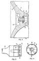
- the centrifugal gas compressor to which the invention is shown applied herein includes an inlet 10 through which gas flows to the impeller which includes a hub portion 12, vanes 14, and a shroud 16.
- the gas compressed by the impeller in operation is passed into a gas collecting scroll 18.
- the impeller is securely fastened to the front end extremity 20 of a drive shaft 22 which extends rearwardly through a gear cover 24 and is driven at a relatively high speed by a gear arrangement, not shown herein.
- a gear arrangement not shown herein.
- the impeller hub portion 12 is made of a permanently molded aluminum alloy casting, such as the alloy C355-T61 available from the Aluminum Company of America, for example.
- the impeller has an axial bore 26 extending through its center, and a counterbored recess 28 at its front.
- a fastener with a threaded shaft, such as cap screw 30, is provided to extend through the bore 26 and into a threaded bore 32 extending from the front face of the extremity 20 concentrically into the shaft forward end portion ( Figures 3 and 4).
- a steel washer 34 and a spring or Belleville washer 36 are fitted on the shaft of the cap screw and seat in the recess 28 when the impeller is tightened to the drive shaft.
- the rear surface of the impeller is provided with a frusto-conical socket 38 machined therein, the circumferential wall 40 tapering outwardly slightly.
- the angle of taper of the circumferential wall 40 is between 7.5° and 8°.
- the driving end portion of the shaft 22 has the basically frusto-conical extremity 20 which is adapted to be received in wedging relation in the socket 38.
- the circumferential wall of the extremity includes a plurality of forwardly-open, axially extending grooves 42 which are circumferentially spaced therearound and alternate with intervening lands 44.
- the material of which the shaft, and particularly the extremity 20, is formed has a compressive yield strength significantly higher than the material forming the socket of the impeller.
- One satisfactory material of which a shaft has been formed is a medium carbon alloy steel, such as that designated 41 L40 which will have a compressive yield strength between about 100,000 (7,030.7 kg/cm 2 ) to about 200,000 psi (14,061.4 kg/cm 2 ), depending upon the particular treatment.
- the circumferential dimension of the shaft extremity 22, as defined by the lands, is slightly larger than the facing circumferential di- . mension of the circumferential wall 40 of the socket 38 in the finally seated relation of the shaft extremity in the socket.
- the circumferential dimension relationships of these parts is such that when the shaft extremity is wedged into place by tightening the fastener 30 ( Figure 2), the lands 44 plastically deform the material of the impeller socket wall 40 in an outward direction at those locations.
- an angle of the taper of the circumferential wall of the extremity, as defined by the lands 44 of between 8.0° and 8.5° has been found satisfactory.
- the diameter of the circumferential wall of the extremity as defined by the lands at the front face of the extremity is nearly 1% larger than the diameter at the seat of the socket 38. Accordingly, when the members as fastened together in their final relationship, by applying a given torque to the fastener 30, the opposing faces of the front end of the extremity 20 and the socket base will not seat tightly.
- the grooves 42 can be relatively shallow since the displacement of the circumferential portions of the socket wall 40 is relatively slight. In viewing the indentations in the socket wall 40 after an installed impeller has been removed, the observer must look closely to find the indentations, but they are readily perceptible with the naked eye.
- the torque capacity is about three times the torque capacity for a smooth surfaced basic cone clutch arrangement. While the torque capacity is very significantly increased, the force required to release the impeller from the shaft extremity is not increased to the extent that any difficulty in practical application is experienced.
- the torque applied to the cap screw 30 is calculated to obtain the plastic deformation referred to above in view of the dimensional relationships.
- the Belleville washer functions to maintain the axial force, but it does not increase substantially the engagement friction in an axial direction.
Landscapes
- Engineering & Computer Science (AREA)
- Chemical & Material Sciences (AREA)
- Physics & Mathematics (AREA)
- General Engineering & Computer Science (AREA)
- Mechanical Engineering (AREA)
- General Physics & Mathematics (AREA)
- Optics & Photonics (AREA)
- General Life Sciences & Earth Sciences (AREA)
- Life Sciences & Earth Sciences (AREA)
- Geochemistry & Mineralogy (AREA)
- Manufacturing & Machinery (AREA)
- Materials Engineering (AREA)
- Organic Chemistry (AREA)
- General Chemical & Material Sciences (AREA)
- Chemical Kinetics & Catalysis (AREA)
- Thermal Sciences (AREA)
- Structures Of Non-Positive Displacement Pumps (AREA)
Claims (7)
Applications Claiming Priority (2)
| Application Number | Priority Date | Filing Date | Title |
|---|---|---|---|
| US22403 | 1979-03-21 | ||
| US06/022,403 US4257744A (en) | 1979-03-21 | 1979-03-21 | Impeller and shaft assembly for high speed gas compressor |
Publications (2)
| Publication Number | Publication Date |
|---|---|
| EP0016643A1 EP0016643A1 (fr) | 1980-10-01 |
| EP0016643B1 true EP0016643B1 (fr) | 1984-01-11 |
Family
ID=21809406
Family Applications (1)
| Application Number | Title | Priority Date | Filing Date |
|---|---|---|---|
| EP80300858A Expired EP0016643B1 (fr) | 1979-03-21 | 1980-03-20 | Rotor et son montage sur l'arbre d'un compresseur à grande vitesse |
Country Status (8)
| Country | Link |
|---|---|
| US (1) | US4257744A (fr) |
| EP (1) | EP0016643B1 (fr) |
| JP (1) | JPS60559B2 (fr) |
| KR (1) | KR830002159A (fr) |
| AU (1) | AU539692B2 (fr) |
| CA (1) | CA1111397A (fr) |
| DE (1) | DE3066072D1 (fr) |
| ES (1) | ES489726A0 (fr) |
Families Citing this family (31)
| Publication number | Priority date | Publication date | Assignee | Title |
|---|---|---|---|---|
| JPS58124002A (ja) * | 1982-01-20 | 1983-07-23 | Toyota Motor Corp | タ−ボチヤ−ジヤのインペラ組み付け方法 |
| US4589822A (en) * | 1984-07-09 | 1986-05-20 | Mici Limited Partnership Iv | Centrifugal blood pump with impeller |
| US4606698A (en) * | 1984-07-09 | 1986-08-19 | Mici Limited Partnership Iv | Centrifugal blood pump with tapered shaft seal |
| US4834628A (en) * | 1986-06-09 | 1989-05-30 | Laing Karsten A | Rotor-magnet unit |
| US4898518A (en) * | 1988-08-31 | 1990-02-06 | Minnesota Mining & Manufacturing Company | Shaft driven disposable centrifugal pump |
| US4927406A (en) * | 1988-12-15 | 1990-05-22 | Beckman Instruments, Inc. | Spring biased drive socket insert for centrifuge rotors |
| US5976388A (en) * | 1997-05-20 | 1999-11-02 | Cobe Cardiovascular Operating Co., Inc. | Method and apparatus for autologous blood salvage |
| US5919125A (en) * | 1997-07-11 | 1999-07-06 | Cobe Laboratories, Inc. | Centrifuge bowl for autologous blood salvage |
| DE59710695D1 (de) * | 1997-09-19 | 2003-10-09 | Abb Turbo Systems Ag Baden | Verdichterradbefestigung für schnellaufende Turbomaschinen |
| US6254349B1 (en) | 1999-07-02 | 2001-07-03 | Ingersoll-Rand Company | Device and method for detachably connecting an impeller to a pinion shaft in a high speed fluid compressor |
| US6499958B2 (en) | 1999-07-02 | 2002-12-31 | Ingersoll-Rand Company | Device and method for detachably connecting an impeller to a pinion shaft in a high speed fluid compressor |
| US6290467B1 (en) | 1999-12-03 | 2001-09-18 | American Standard International Inc. | Centrifugal impeller assembly |
| US6461111B1 (en) * | 2000-08-25 | 2002-10-08 | Ingersoll-Rand Company | Tapered polygon coupling |
| DE10122516B4 (de) * | 2001-05-09 | 2006-10-19 | Mtu Friedrichshafen Gmbh | Laufrad |
| US6663343B1 (en) | 2002-06-27 | 2003-12-16 | Sea Solar Power Inc | Impeller mounting system and method |
| DE10229631B4 (de) | 2002-07-02 | 2024-05-08 | BSH Hausgeräte GmbH | Gebläsevorrichtung, insbesondere für Öfen zum Wärmebehandeln von Nahrungsmitteln, und ein solcher Ofen |
| GB0224721D0 (en) * | 2002-10-24 | 2002-12-04 | Holset Engineering Co | Compressor wheel assembly |
| JP4217091B2 (ja) * | 2003-03-25 | 2009-01-28 | 本田技研工業株式会社 | エンジン冷却用ウォータポンプ |
| JP4554189B2 (ja) * | 2003-11-26 | 2010-09-29 | 株式会社エンプラス | 遠心式羽根車 |
| EP1746290A1 (fr) * | 2005-07-20 | 2007-01-24 | Rietschle Thomas Schopfheim GmbH | Compresseur centrifuge |
| US20080229742A1 (en) * | 2007-03-21 | 2008-09-25 | Philippe Renaud | Extended Leading-Edge Compressor Wheel |
| DE102007044646A1 (de) * | 2007-09-18 | 2009-03-26 | Ksb Aktiengesellschaft | Laufradbefestigung |
| US10113428B2 (en) * | 2011-11-15 | 2018-10-30 | Borgwarner Inc. | Flow rotor, in particular turbine wheel |
| DE102012218692B4 (de) * | 2012-10-15 | 2014-11-20 | Continental Automotive Gmbh | Abgasturboladerwelle mit dieser verbundenem Laufrad |
| FR2998920B1 (fr) * | 2012-12-04 | 2018-07-27 | Thy Engineering | Machine tournante telle qu'une turbine ou un compresseur. |
| US10267335B1 (en) * | 2015-09-23 | 2019-04-23 | Anthony Freakes | Methods and apparatus for mounting an impeller with positional repeatability |
| KR101869906B1 (ko) * | 2016-06-01 | 2018-07-13 | (주)엠프로텍 | 나사결합 및 가이드(센터링)를 이용한 샤프트와 임펠러의 조립을 위한 장치 |
| CN106321504B (zh) * | 2016-09-23 | 2019-03-05 | 扬州大学 | 一种兼顾对中和紧固轴流泵叶轮并对其进行实时监控的方法 |
| EP3462038B1 (fr) * | 2017-07-31 | 2020-07-08 | Mitsubishi Electric Corporation | Ventilateur et machine intérieure de dispositif de climatisation comportant un ventilateur |
| CN113606187B (zh) * | 2021-09-13 | 2023-05-16 | 安徽环茨智能科技有限公司 | 高速离心风机三元叶轮的纹路型叶片 |
| JP7796504B2 (ja) * | 2021-10-11 | 2026-01-09 | 株式会社荏原製作所 | 羽根車およびポンプ |
Family Cites Families (14)
| Publication number | Priority date | Publication date | Assignee | Title |
|---|---|---|---|---|
| DE503541C (de) * | 1930-07-24 | Schweinfurter Praez S Kugel La | Konische Spannhuelse zur Befestigung von Maschinenteilen auf Achsen, Wellen o. dgl. | |
| US1403309A (en) * | 1918-01-14 | 1922-01-10 | Westinghouse Electric & Mfg Co | Means for attaching gears to shafts |
| US1445142A (en) * | 1918-10-07 | 1923-02-13 | Curtiss Aeroplane & Motor Co | Propeller mounting |
| FR567958A (fr) * | 1922-09-08 | 1924-03-12 | Cie Forges Et Acieries Marine | Dispositif pour le montage des volants sur leur arbre |
| US1511910A (en) * | 1924-05-14 | 1924-10-14 | Rolls Royce | Change-speed mechanism for mechanically-propelled vehicles |
| US1557099A (en) * | 1924-11-21 | 1925-10-13 | Stewart Warner Speedometer | Shaft and detachable gear |
| US1771769A (en) * | 1925-09-12 | 1930-07-29 | Skayef Ball Bearing Company | Taper and the art of mounting this |
| US2119334A (en) * | 1934-08-16 | 1938-05-31 | William S Leffler | Self-affixing and self-tightening connection for rotating and rotated members |
| US2239641A (en) * | 1938-07-25 | 1941-04-22 | Westinghouse Electric & Mfg Co | Elastic sleeve connection |
| DE1105669B (de) * | 1959-03-06 | 1961-04-27 | Oskar E Peter | Spannelement zur Verbindung von Naben mit einer Welle |
| US3143366A (en) * | 1959-03-27 | 1964-08-04 | Harry J Nichols | Quick keyless couplings |
| US3601501A (en) * | 1970-02-26 | 1971-08-24 | John G Johnson | Gas compressor impeller and shaft assembly |
| US3673777A (en) * | 1970-09-03 | 1972-07-04 | Black & Decker Mfg Co | Blade mounting means |
| US4118134A (en) * | 1974-04-08 | 1978-10-03 | Lescoa, Inc. | Fastener joint and method thereof |
-
1979
- 1979-03-21 US US06/022,403 patent/US4257744A/en not_active Expired - Lifetime
- 1979-03-21 KR KR1019800001183A patent/KR830002159A/ko not_active Ceased
-
1980
- 1980-03-14 CA CA347,693A patent/CA1111397A/fr not_active Expired
- 1980-03-18 AU AU56544/80A patent/AU539692B2/en not_active Expired - Fee Related
- 1980-03-20 EP EP80300858A patent/EP0016643B1/fr not_active Expired
- 1980-03-20 ES ES489726A patent/ES489726A0/es active Granted
- 1980-03-20 DE DE8080300858T patent/DE3066072D1/de not_active Expired
- 1980-03-21 JP JP55034852A patent/JPS60559B2/ja not_active Expired
Also Published As
| Publication number | Publication date |
|---|---|
| AU5654480A (en) | 1980-09-25 |
| ES8103292A1 (es) | 1981-02-16 |
| JPS55128697A (en) | 1980-10-04 |
| CA1111397A (fr) | 1981-10-27 |
| US4257744A (en) | 1981-03-24 |
| KR830002159A (ko) | 1983-05-23 |
| DE3066072D1 (en) | 1984-02-16 |
| EP0016643A1 (fr) | 1980-10-01 |
| AU539692B2 (en) | 1984-10-11 |
| ES489726A0 (es) | 1981-02-16 |
| JPS60559B2 (ja) | 1985-01-08 |
Similar Documents
| Publication | Publication Date | Title |
|---|---|---|
| EP0016643A1 (fr) | Rotor et son montage sur l'arbre d'un compresseur à grande vitesse | |
| US6422657B2 (en) | Vehicle wheel hub mounting system | |
| US6364426B1 (en) | Vehicle wheel hub and bearing unit assembly and method for producing same | |
| US6280096B1 (en) | Rolling bearing unit for supporting vehicle wheel | |
| US7121947B2 (en) | Coupling device | |
| US6959493B2 (en) | Brake rotor and wheel bearing assembly having maximum acceptable runout variation | |
| US5988761A (en) | Vehicle brake and hub attachment system and method | |
| EP0797007B1 (fr) | Ventilateur et son ensemble d'entraínement | |
| EP1288513B1 (fr) | Système et procédé de montage d'un arbre dans un corps cylindrique | |
| CA1172676A (fr) | Montage compose d'un roulement et d'un joint universel | |
| JP2002115708A (ja) | ボルト部分と支持リングを備えた弛めることができる車輪用連結要素 | |
| US4144755A (en) | V-belt pulley | |
| US20030098007A1 (en) | Torque transmission device having torque limiter | |
| US20040047708A1 (en) | Wheel end assembly with locking fastener | |
| US6663343B1 (en) | Impeller mounting system and method | |
| CA2432769A1 (fr) | Montage d'un element de fixation sur un panneau et ensemble de fixation-panneau | |
| US8002640B2 (en) | Wheel hub/universal joint assembly with end teeth and wheel bearing | |
| US6062737A (en) | Wheel hub retention apparatus | |
| US4775190A (en) | Hub assembly for drivable wheel | |
| US20050231025A1 (en) | Wheel support rolling bearing unit and manufacturing method therefor | |
| US4721009A (en) | Gear wheel shaft assembly | |
| US5356236A (en) | Device for connecting two elements in rotation | |
| JPS6322701A (ja) | ホイ−ルハブ用連結装置 | |
| US5626532A (en) | Drive assembly with interference-fit mounted lightweight non-ferrous pulley | |
| US5590467A (en) | Method of making a blast wheel |
Legal Events
| Date | Code | Title | Description |
|---|---|---|---|
| PUAI | Public reference made under article 153(3) epc to a published international application that has entered the european phase |
Free format text: ORIGINAL CODE: 0009012 |
|
| AK | Designated contracting states |
Designated state(s): BE DE FR GB IT |
|
| 17P | Request for examination filed |
Effective date: 19810325 |
|
| ITF | It: translation for a ep patent filed | ||
| GRAA | (expected) grant |
Free format text: ORIGINAL CODE: 0009210 |
|
| RAP1 | Party data changed (applicant data changed or rights of an application transferred) |
Owner name: MCQUAY-PERFEX INC. |
|
| AK | Designated contracting states |
Designated state(s): BE DE FR GB IT |
|
| PG25 | Lapsed in a contracting state [announced via postgrant information from national office to epo] |
Ref country code: BE Effective date: 19840111 |
|
| REF | Corresponds to: |
Ref document number: 3066072 Country of ref document: DE Date of ref document: 19840216 |
|
| ET | Fr: translation filed | ||
| PLBE | No opposition filed within time limit |
Free format text: ORIGINAL CODE: 0009261 |
|
| STAA | Information on the status of an ep patent application or granted ep patent |
Free format text: STATUS: NO OPPOSITION FILED WITHIN TIME LIMIT |
|
| 26N | No opposition filed | ||
| REG | Reference to a national code |
Ref country code: FR Ref legal event code: CD |
|
| ITTA | It: last paid annual fee | ||
| PGFP | Annual fee paid to national office [announced via postgrant information from national office to epo] |
Ref country code: GB Payment date: 19920311 Year of fee payment: 13 |
|
| PGFP | Annual fee paid to national office [announced via postgrant information from national office to epo] |
Ref country code: FR Payment date: 19920323 Year of fee payment: 13 |
|
| PGFP | Annual fee paid to national office [announced via postgrant information from national office to epo] |
Ref country code: DE Payment date: 19920430 Year of fee payment: 13 |
|
| PG25 | Lapsed in a contracting state [announced via postgrant information from national office to epo] |
Ref country code: GB Effective date: 19930320 |
|
| GBPC | Gb: european patent ceased through non-payment of renewal fee |
Effective date: 19930320 |
|
| PG25 | Lapsed in a contracting state [announced via postgrant information from national office to epo] |
Ref country code: FR Effective date: 19931130 |
|
| PG25 | Lapsed in a contracting state [announced via postgrant information from national office to epo] |
Ref country code: DE Effective date: 19931201 |
|
| REG | Reference to a national code |
Ref country code: FR Ref legal event code: ST |