EP0017100A2 - Verfahren und Einrichtung zur Schmiermittelzuführung an einer Kolben-Zylinderanordnung - Google Patents
Verfahren und Einrichtung zur Schmiermittelzuführung an einer Kolben-Zylinderanordnung Download PDFInfo
- Publication number
- EP0017100A2 EP0017100A2 EP80101491A EP80101491A EP0017100A2 EP 0017100 A2 EP0017100 A2 EP 0017100A2 EP 80101491 A EP80101491 A EP 80101491A EP 80101491 A EP80101491 A EP 80101491A EP 0017100 A2 EP0017100 A2 EP 0017100A2
- Authority
- EP
- European Patent Office
- Prior art keywords
- lubricant
- working
- pressure
- sealing element
- piston
- Prior art date
- Legal status (The legal status is an assumption and is not a legal conclusion. Google has not performed a legal analysis and makes no representation as to the accuracy of the status listed.)
- Granted
Links
- 239000000314 lubricant Substances 0.000 title claims abstract description 81
- 238000000034 method Methods 0.000 title claims abstract description 11
- 238000007789 sealing Methods 0.000 claims abstract description 33
- 230000000737 periodic effect Effects 0.000 claims description 5
- 230000007704 transition Effects 0.000 claims description 5
- 230000001360 synchronised effect Effects 0.000 claims description 4
- 230000010349 pulsation Effects 0.000 claims description 2
- 239000007787 solid Substances 0.000 claims 1
- 238000012423 maintenance Methods 0.000 abstract 1
- 238000010586 diagram Methods 0.000 description 7
- 230000001154 acute effect Effects 0.000 description 3
- 239000000463 material Substances 0.000 description 3
- 230000006835 compression Effects 0.000 description 2
- 238000007906 compression Methods 0.000 description 2
- 230000003247 decreasing effect Effects 0.000 description 2
- 238000006073 displacement reaction Methods 0.000 description 2
- 230000000903 blocking effect Effects 0.000 description 1
- 230000000694 effects Effects 0.000 description 1
- 230000035515 penetration Effects 0.000 description 1
- 239000003566 sealing material Substances 0.000 description 1
- 125000006850 spacer group Chemical group 0.000 description 1
- 238000004073 vulcanization Methods 0.000 description 1
Images

Classifications
-
- F—MECHANICAL ENGINEERING; LIGHTING; HEATING; WEAPONS; BLASTING
- F04—POSITIVE - DISPLACEMENT MACHINES FOR LIQUIDS; PUMPS FOR LIQUIDS OR ELASTIC FLUIDS
- F04B—POSITIVE-DISPLACEMENT MACHINES FOR LIQUIDS; PUMPS
- F04B43/00—Machines, pumps, or pumping installations having flexible working members
- F04B43/08—Machines, pumps, or pumping installations having flexible working members having tubular flexible members
- F04B43/084—Machines, pumps, or pumping installations having flexible working members having tubular flexible members the tubular member being deformed by stretching or distortion
-
- F—MECHANICAL ENGINEERING; LIGHTING; HEATING; WEAPONS; BLASTING
- F01—MACHINES OR ENGINES IN GENERAL; ENGINE PLANTS IN GENERAL; STEAM ENGINES
- F01M—LUBRICATING OF MACHINES OR ENGINES IN GENERAL; LUBRICATING INTERNAL COMBUSTION ENGINES; CRANKCASE VENTILATING
- F01M1/00—Pressure lubrication
- F01M1/16—Controlling lubricant pressure or quantity
Definitions
- the invention relates to a method for supplying lubricant to a piston-cylinder arrangement with at least one working chamber under pulsating working pressure and with at least one flexible, bellows-like, in particular tubular sealing element, the latter being supported on its surface against a lubricant chamber, the lubricant flows through this room with continuous supply.
- the invention further relates to a device for supplying lubricant to a piston-cylinder arrangement with at least two working members defining a pulsating working chamber and with at least one flexible, bellows-like, in particular tubular sealing element, which is connected to a through a lubricant chamber connected to a lubricant supply device supports the first working member formed support surface during its periodic deformation corresponding to the pulsation of the working space.
- a method and a device of the aforementioned type are known from DE-O S 25 54 733.
- the support of a tubular sealing element described in detail here via a lubricant on a cylindrical support surface takes place with lubricant supply also during the pressure working strokes ie the strokes with decreasing working space volume with pump operation or with increasing working space volume with motor operation.
- the supply takes place, for example, by injecting a mass flow that is more or less independent of the counterpressure and then leaves the lubricant chamber via a throttle point in a low-pressure chamber.
- working pressure regardless of the fluctuations in the pressure in the working space (hereinafter referred to as "working pressure"), an equilibrium can be achieved between this and the pressure in the lubricant space, thus avoiding direct contact or mixed friction between the sealing element and the support surface.
- working pressure a lubricant supply
- a pump pressure which is in any case above the maximum values of the working pressure, as well as a suitable control or regulation of the supply volume flow. This is associated with a comparatively high outlay.
- the object of the invention is therefore to provide a method or a device for supplying lubricant to a piston-cylinder arrangement with a flexible sealing element of the type mentioned, which basically manages with a lower lubricant supply pressure with respect to the working pressure and does not control or regulate a constant flow rate in the Lubricant supply required.
- the solution to this problem according to the invention is characterized in terms of the method and the device by the method described in claim 1 and features specified in claim 4.
- a quantity of lubricant can be introduced into the lubricant space between the sealing element and the support surface with a comparatively low supply pressure at time intervals with a comparatively low working pressure, which is sufficient, taking into account the throttled outflow, for reliable support of the sealing element without contact or mixed friction on the support surface.
- a backflow into the lower pressure lubricant supply device is expediently prevented by a check valve arrangement, so that the required balance between the lubricant pressure and the working pressure on the sealing element can be established quickly. If necessary, however, it is also possible to dispense with a defined non-return valve or a non-return valve arrangement, provided that the non-return flow in the supply system allows a sufficient support pressure to be built up in the lubricant chamber.
- a time course of the lubricant supply pressure that is independent of the working strokes of the piston-cylinder arrangement, preferably at least approximately constant, can be provided with the advantage of particular simplicity.
- this enables a common lubricant supply for a multiple-piston-cylinder arrangement with a corresponding plurality of sealing elements in a simple manner.
- the lubricant supply pressure has a time curve with maximum values that is synchronous with respect to the periodic change in the working space of the piston-cylinder arrangement, with maximum values in working stroke ranges between the maximum values of the working pressure, i.e. at low working pressures.
- Such an embodiment is particularly suitable for arrangements with only one sealing element or a small number of such elements, it being possible for a lubricant pump to be coupled to the drive of the piston-cylinder pair in question.
- the check valve arrangement has at least one valve member arranged in the area of the lubricant supply opening in the lubricant chamber.
- This arrangement of the valve member of the check valve arrangement results in a particularly low-inertia blocking of the lubricant supply channel when the increase in the working pressure begins.
- a cylinder 1 as the first working member and a piston 2 as the second working member are connected to one another via a tubular sealing element 3, which is supported on a cylindrical support surface 4 of the first working member.
- the support surface 4 forms a toroidal outwardly curved transition surface section 4a.
- the connection area 3 a is integrally connected, for example by vulcanization, to an intermediate ring 1 a of the cylinder 1.
- the mouth of the lubricant supply which is yet to be explained, is located in this connection area.
- the sealing element is also integrally connected to a conical surface of the piston 2.
- a helical compression spring 2a presses the shaft 2b, which is displaceably guided in the cylinder 1, downward against an oscillating drive member, so that the working space 5 formed within the sealing element is reduced during a movement in accordance with arrow X.
- the piston 2 assumes its lowest position at the maximum working space volume.
- the work space is connected by a cover 6 with supply and discharge line 6a to a valve arrangement (not shown) for a mode of operation of the device as a pump.
- a gap-shaped lubricant space 3b of small radial thickness Between the sealing element 3 and the support wall 4 there is a gap-shaped lubricant space 3b of small radial thickness, the lubricant filling of which excludes contact between the sealing element and the support surface during the oscillating longitudinal expansion of the sealing element in accordance with the piston movement.
- a motor unit 7 with a drive shaft 7a and cams 7b As a drive for the piston movement, a motor unit 7 with a drive shaft 7a and cams 7b is provided, against which the latter of the piston shaft 2b is pressed by the compression spring 2a.
- a lubricant supply device is also coupled to the motor unit 7 with a pump 8 via a schematically indicated shaft 8a and a cam 8b.
- a check valve 8d can be inserted in the lubricant supply line 8c, but preferably the mouth 9 of the lubricant supply is provided with a low-inertia check valve member 15.
- the lubricant feed opening 9 is located on the underside of an annular body 10 provided with corresponding passage grooves, which forms the transition surface section 4a on its upper side.
- the diagrams in FIG. 2 relate to an operation of the piston-cylinder arrangement as a pump, ie with a high working pressure with a decreasing working space volume.
- Diagram (a) shows the course of the stroke h of the working piston 2 and the pump stroke h Z of the lubricant supply pump over the time t. This method of operation corresponds to a synchronized lubricant supply in the working strokes with increasing work space volume.
- the associated course of the lubricant supply pressure p is indicated in curve B of diagram (b). This feed allows a comparatively low maximum supply pressure p Z1 .
- the time course of the lubricant volume flow v Z is indicated in curve B in diagram (c).
- an asynchronous lubricant supply can be used, for example with an essentially constant supply pressure p ZO according to line A in diagram (b).
- p ZO supply pressure
- a radial channel 11 in the cylinder 1 a circumferential distributor groove 12 on the ring body 10 and a plurality of radial feed grooves 13 within the end face 10a are connected to the feed line 8c.
- the radial feed grooves 13 open into an inner circumferential groove 14 between the ring body 10 and the cylinder 1, which acts as an end distributor for the lubricant supply into the gap 3b.
- the mouth 9 itself is formed by a circumferential groove with a flat, triangular cross section, into which an annular, radially deformable valve member 15 is inserted.
- the base side 15a of the ring cross section facing the sealing element 3 has a width b, which is dimensioned substantially larger than the radial cross-sectional height d, so that there are rear-side surfaces 15b of the ring which are inclined at an acute angle to the cylindrical part of the support surface 4.
- the annular valve member 15 is deformed radially inward, as is indicated by the broken line in FIG. 3a. This results in passage channels which open at an acute angle into the lubricant chamber 3b on the rear side surfaces 15b of the ring and which, when the working pressure predominates, close again automatically with radial expansion of the ring outward.
- the annular valve member can optionally be made of a deformation-resistant but comparatively flexible material, in particular of a sliding-friendly plastic, so that small pressure differences are sufficient for rapid valve actuation.
- the low mass of the annular valve member also contributes to a low-inertia function.
- annular valve member 15 On the outside of the annular valve member 15 is an annular extension 15c running in the circumferential direction provided that engages flush in the circumferential groove 14 and secures the valve member against axial displacement.
- recesses 15d are provided in the annular extension 15c, which engage radially inwards in the region of the rear side surfaces 15b.
- the lubricant can pass from the circumferential groove 14 into the passage channels formed on the rear side surfaces 15b in the case of radial inward deformation when the radial inward deformation has only reached a slight degree. This also contributes to a low-delay function of the check valve.
- a circumferential distributor groove 22 as well as radial channels 23 and an end distributor groove 24 adjoin the feed line 8c and the radial channel 11 within the right end face of an annular body 20.
- the transition surface section 4a forms an annular valve member 25, which is separated from the ring body 20 and is axially displaceable because of the deformability of the sealing element connection region 3a and which closes the lubricant supply opening with its rear surface 25a when the working pressure exceeds the lubricant supply pressure.
- the valve member 25 is axially displaced to the left in the sense of FIG. 4, the lower section of the rear surface 25a clears the passage into the lubricant chamber 3b. Again, there is an acute angle mouth of the lubricant flow with respect to the cylindrical part of the support surface 4, which contributes to a uniform and rapid distribution of the lubricant.
- the annular valve member 25 can, in addition to or if necessary, have a radial deformability in addition to its axial displacement, which can be easily achieved by appropriate choice of material.
- the cross section of the ring body can easily twist during the inward deformation in such a way that the inner edge region of the rear side surface 25a lifts off the cylinder, while the outer region of the ring continues to be supported. In this way, a slight deformation of the ring body is sufficient for the valve actuation.
- an axially displaceable, annular valve member 35 is provided, which rests with its right end face 35a in the flow state against a corresponding, flat end face of the cylinder 1 and is displaced to the left under the effect of the lubricant supply pressure for opening .
- the valve member is fitted radially into a spacer ring 36 which has circumferential distributor grooves 32a and 32b on its right end face and radial channels 33 for the passage of the lubricant to the right end face of the valve member 35.
- Such an implementation comes into play in particular also for the use of non-deformable, wear-resistant materials for the valve member 35.
Landscapes
- Engineering & Computer Science (AREA)
- Mechanical Engineering (AREA)
- General Engineering & Computer Science (AREA)
- Details Of Reciprocating Pumps (AREA)
- Sealing Devices (AREA)
- Lubrication Of Internal Combustion Engines (AREA)
- Sliding-Contact Bearings (AREA)
Abstract
Description
- Die Erfindung bezieht sich auf ein Verfahren zur Schmiermittelzuführung an einer Kolben-Zylinderanordnung mit mindestens einem unter pulsierende Arbeitsdruck stehenden Arbeitsraum sowie mit mindestens einem verformungsweichen, balgartigen, insbeson- dere schlauchförmigen Dichtungselement, welch letzteres sich an seiner Oberfläche an einem Schmiermittelraum abstützt, wobei das Schmiermittel diesen Raum unter laufender Zuführung durchströmt. Die Erfindung bezieht sich weiter auf eine Einrichtung zur Schmiermittelzuführung an einer Kolben-Zylinderanordnung mit mindestens zwei einen pulsierenden Arbeitsraum bestimmenden Arbeitsgliedern sowie mit mindestens einem verformungsweichen, balgartigen, insbesondere schlauchförmigen Dichtungselement, das sich über einen mit einer Schmiermittel-Zuführvorrichtung verbundenen Schmiermittelraum an einer durch ein erstes Arbeitsglied gebildeten Stützfläche während seiner der Pulsation des Arbeitsraumes entsprechenden, periodischen Verformung abstützt.
- Ein Verfahren und eine Einrichtung der vorgenannten Art sind bekannt aus der DE-OS 25 54 733. Die hier im einzelnen beschriebene Abstützung eines schlauchförmigen Dichtungselementes über ein Schmiermittel an einer zylinderischen Stützfläche erfolgt mit Schmiermittelzuführung auch während der Druck-Arbeitshübe d.h. der Hübe mit abnehmendem Arbeitsraumvolumen bei Pumpenbetrieb bzw. mit zunehmendem Arbeitsraumvolumen bei Motorbetrieb. Die Zuführung erfolgt beispielsweise durch Einpressen eines vom Gegendruck mehr oder weniger unabhängigen Mengenstromes, der den Schmiermittelraum anschliessend über eine Drosselstelle in einen Niederdruckraum verlässt.
- Auf diese Weise lässt sich unabhängig von den Schwankungen des Druckes im Arbeitsraum (im folgenden kurz "Arbeitsdruck" genannt) ein Gleichgewicht zwischen diesem und dem Druck im Schmiermittelraum erzielen und-damit eine unmittelbare Berührung oder Mischreibung zwischen Dichtungselement und Stützfläche vermeiden. Allerdings erfordert eine solche Schmiermittelzuführung einen Pumpendruck, der jedenfalls über den Maximalwerten des Arbeitsdruckes liegt, sowie eine geeignete Steuerung oder Regelung des Zuführ-Mengenstromes. Dies ist mit einem vergleichsweise hohen Aufwand verbunden.
- Aufgabe der Erfindung ist daher die Schaffung eines Verfahrens bzw. einer Einrichtung zur Schmiermittelzuführung an einer Kolben-Zylinderanordnung mit nachgiebigem Dichtungselement der eingangs genannten Art, die grundsätzlich mit bezüglich des Arbeitsdruckes geringerem Schmiermittel-Zuführdruck auskommt und keiner Steuerung oder Regelung für einen konstanten Mengenstrom bei der Schmiermittelzuführung bedarf. Die erfindungsgemässe Lösung dieser Aufgabe kennzeichnet sich hinsichtlich des Verfahrens bzw. der Einrichtung durch die im Patentanspruch 1 bzw. im Patentanspruch 4 angegebenen Merkmale.
- Zufolge dieser Lösung kann in Zeitintervallen mit vergleichsweise niedrigem Arbeitsdruck in den Schmiermittelraum zwischen Dichtungselement und Stützfläche mit vergleichsweise geringem Zuführdruck eine Schmiermittelmenge eingebracht werden, die unter Berücksichtigung der gedrosselten Abströmung für eine sichere Abstützung des Dichtungselementes ohne Berührung oder Mischreibung an der Stützfläche ausreicht. Dabei wird zweckmässig eine Rückströmung in die mit niedrigerem Druck arbeitende Schmiermittel-Zuführvorrichtung durch eine Rückschlagventilanordnung verhindert, so dass sich das erforderliche Gleichgewicht zwischen Schmiermitteldruck und Arbeitsdruck am Dichtungselement rasch einstellen kann. Gegebenenfalls kann aber auch auf eine definierte Rückstromsperrung bzw. eine Rückschlagventilanordnung verzichtet werden, sofern der Rückströmungswiderstand im Zuführsystem den Aufbau eines ausreichenden Stützdruckes im Schmiermittelraum zulässt.
- Gemäss einer Weiterbildung der Erfindung kann mit dem Vorteil besonderer Einfachheit ein von den Arbeitshüben der Kolben-Zylinderanordnung unabhängiger, vorzugsweise wenigstens annähernd konstanter Zeitverlauf des Schmiermittel-Zuführdruckes vorgesehen werden. Dies ermöglicht insbesondere in einfacher Weise eine gemeinsame Schmiermittelzuführung für eine Mehrfach-Kolben-Zylinderanordnung mit einer entsprechenden Mehrzahl von Dichtungselementen.
- Umgekehrt sieht eine andere Weiterbildung der Erfindung vor, dass der Schmiermittel-Zuführdruck einen bezüglich der periodischen Arbeitsraumveränderung der Kolben-Zylinderanordnung synchronen Zeitverlauf mit Maximalwerten In Arbeitshubbereichen zwischen den Maximalwerten des Arbeitsdruckes, d.h. bei niedrigen Arbeitsdrücken aüfweist. Eine solche Ausführung bietet sich vor allem für Anordnungen mit nur einem Dichtungselement oder einer geringen Anzahl solcher Elemente an, wobei jeweils eine Schmiermittelpumpe mit dem Antrieb der betreffenden Kolben-Zylinderpaarung gekoppelt werden kann.
- Eine wesentliche Weiterbildung der erfindungsgemässen Einrichtung kennzeichnet sich dadurch, dass die Rückschlagventilanordnung wenigstens ein im Bereich der Schmiermittelzuführmündung in den Schmiermittelraum angeordnetes Ventilglied aufweist. Durch diese Anordnung des Ventilgliedes der Rückschlagventilanordnung ergibt sich eine besonders trägheitsarme Sperrung des Schmiermittel-Zuführkanals bei Einsetzen der Erhöhung des Arbeitsdruckes. Vor allem bei sehr hohen Arbeitsdrücken, die eine Berücksichtigung der Kompressibilität des Schmiermittels und der elastischen Nachgiebigkeit der Zuführleitungen und anderer Zuführorgane erforderlich machen würden, bedeutet dies eine wesentliche Entlastung der gesamten Zuführvorrichtung und vermeidet eine Verminderung des für die Abstützung wirksamen Schmiermittelvolumens, sichert also das Dichtungselement gegen Berührung mit den Unebenheiten der Schmiermittel-Zuführmündung und damit gegen Beschädigung.
- Die Erfindung wird weiter anhand der in den Zeichnungen dargestellten Ausführungsbeispiele erläutert. Hierin zeigt
- Fig. 1 eine Kolben-Zylinderanordnung mit schlauchförmigem Dichtungselement und schematisch angedeuteter Antriebs- und Schmiermittel-Zuführvorrichtung,
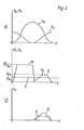
- Fig. 2 in drei Diagrammen (a), (b) und (c) den Verlauf ver--schiedener für die Schmiermittelzuführung wesentlicher Betriebsgrössen der Kolben-Zylinderanordnung,
- Fig. 3a, in grösserem Massstab einen Axialschnitt bzw. Quer-Fig. 3b axialschnitt des Anschlussbereiches eines Dichtungsschlauches an einen Arbeitszylinder mit Rückschlagventilanordnung und
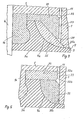
- Fig. 4, je einen Axialschnitt eines Dichtungsschlauch-An-Fig. 5 schlussbereiches mit zwei abgewandelten Ausführungen von Rückschlagventilanordnungen.
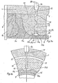
- Bei der Anordnung nach Fig. 1 sind ein Zylinder 1 als erstes Arbeitsglied und ein Kolben 2 als zweites Arbeitsglied über ein schlauchförmiges Dichtungselement 3 miteinander verbunden, das sich an einer zylinderischen Stützfläche 4 des ersten Arbeitsgliedes abstützt. Im radialverstärkten Anschlussbereich 3a des Dichtungselementes 3 an den Zylinder 1 bildet die Stützfläche 4 einen toroidförmig nach aussen gekrümmten Uebergangs-Oberflächenabschnitt 4a. Der Anschlussbereich 3a ist stoffschlüssig, beispielsweise durch Vulkanisation, mit einem Zwischenring la des Zylinders 1 verbunden. In diesem Anschlussbereich befindet sich die Mündung der noch zu erläuternden Schmiermittelzuführung. Am entgegengesetzten Ende ist das Dichtungselement ebenfalls stoffschlüssig mit einer Kegelfläche des Kolbens 2 verbunden. Eine Schrauben-Druckfeder 2a drückt den im Zylinder 1 verschiebbar geführten Schaft 2b nach unten gegen ein oszillierendes Antriebsglied, so dass der innerhalb des Dichtungselementes gebildete Arbeitsraum 5 bei einer Bewegung gemässPfeilX verkleinert wird. In der Darstellung nimmt der Kolben 2 seine unterste Stellung bei maximalem Arbeitsraumvolumen ein. Nach oben ist der Arbeitsraum durch einen Deckel 6 mit Zuführ- und Ausstossleitung 6a zu einer nicht dargestellten Ventilanordnung für eine Arbeitsweise der Einrichtung als Pumpe verbunden. Zwischen dem Dichtungselement 3 und der Stützwandung 4 befindet sich ein spaltförmiger Schmiermittelraum 3b geringer radialer Dicke, dessen Schmiermittelfüllung eine Berührung zwischen Dichtungselement und Stützfläche bei der oszillierenden Längsdehnung des Dichtungselementes entsprechend der Kolbenbewegung ausschliesst. Als Antrieb für die Kolbenbewegung ist ein Motoraggregat 7 mit Antriebswelle 7a und Nocken 7b vorgesehen, gegen welch letzteren der Kolbenschaft 2b durch die Druckfeder 2a angepresst wird. Mit dem Motoraggregat 7 ist ferner eine Schmiermittel-Zuführvorrichtung mit einer Pumpe 8 über eine schematisch angedeutete Welle 8a und einem Nocken 8b gekoppelt. In der Schmiermittel-Zuführleitung 8c kann beispielsweise ein Rückschlagventil 8d eingefügt werden, jedoch ist vorzugsweise die Mündung 9 der Schmiermittelzuführung mit einem trägheitsarm wirkenden Rückschlag-Ventilglied 15 versehen. Die Schmiermittel-Zuführmündung 9 befindet sich an der mit entsprechenden Durchlassnuten versehenen Unterseite eines Ringkörpers 10, der an seiner Oberseite den Uebergangs-Oberflächenabschnitt 4a bildet. Bei der oszillierenden Dehnung des Dichtungselementes werden die Zugkräfte innerhalb des Dichtungsmaterials durch die Krümmung dieses Oberflächenabschnitts nach aussen umgelenkt und auf die stoffschlüssige Verbindung zum Zwischenring la verteilt.
- Die Diagramme in Fig. 2 beziehen sich auf einen Betrieb der Kolbenzylinder-Anordnung als Pumpe, d.h. mit hohem Arbeitsdruck bei abnehmendem Arbeitsraumvolumen. Im Diagramm (a) ist der Verlauf des Hubes h des Arbeitskolbens 2 und des Pumpenhubes hZ der Schmiermittel-Zuführpumpe über der Zeit t angedeutet. Diese Arbeitsweise entspricht einer synchronisierten Schmiermittelzuführung in den Arbeitshüben mit zunehmendem Arbeitsraumvolumen. Der zugehörige Verlauf des Schmiermittel-Zuführdruckes p ist in der Kurve B des Diagrammes (b) angedeutet. Diese Zuführung erlaubt einen vergleichsweise geringen Maximal-Zuführdruck pZ1. Der Zeitverlauf des Schmiermittel-Mengenstromes vZ ist im Diagramm (c) in der Kurve B angedeutet. Andererseits kann mit den in der Einleitung erwähnten Vorteilen eine asynchronische Schmiermittelzuführung angewendet werden, beispielsweise mit einem im wesentlichen konstanten Zuführdruck pZO gemäss Linie A im Diagramm (b). Auch hier ergibt sich eine Schmiermitteleindringung in den Raum 3b der Anordnung nach Fig. 1 im Bereich der Arbeitshübe mit zunehmendem Arbeitsraumvolumen, d.h. bei geringem Arbeitsdruck, mit einem Mengenstrom vZ gemäss Kurve-A im Diagramm (c).
- In Fig. 3a und 3b ist die Ausbildung der Schmiermittel-Zuführmündung mit Rückschlagventil an der Stirnfläche 10a des Ringkörpers 10 im einzelnen dargestellt. An die Zuführleitung 8c schliesst sich ein Radialkanal 11 im Zylinder 1 sowie eine Umfangs-Verteilernut 12 am Ringkörper 10 und weiter eine Mehrzahl von radialen Zuführnuten 13 innerhalb der Stirnfläche 10a an. Die radialen Zuführnuten 13 münden in eine innere Umfangsnut 14 zwischen Ringkörper 10 und Zylinder 1, die als Endverteiler für die Schmiermittelzuführung in den Spaltraum 3b wirkt. Die Mündung 9 selbst wird durch eine im Querschnitt flach-dreieckförmige Umfangsnut gebildet, in die ein ringförmiges, radial verformbares Ventilglied 15 eingesetzt ist. Die dem Dichtungselement 3 zugewandte Basisseite 15a des Ringquerschnitts weist eine Breite b auf, die wesentlich grösser als die radiale Querschnittshöhe d bemessen ist, so dass sich gegen den zylinderischen Teil der Stützfläche 4 spitzwinklig geneigte Rückseitenflächen 15b des Ringes ergeben. Sobald der Schmiermittel-Zuführdruck den auf die Innenseite des Dichtungselementes wirkenden Arbeitsdruck ausreichend übersteigt, wird das ringförmige Ventilglied 15 radial einwärts verformt, wie dies in Fig. 3a strichliert angedeutet ist. Damit ergeben sich an den Rückseitenflächen 15b des Ringes spitzwinklig in den Schmiermittelraum 3b einmündende Durchlasskanäle, die sich bei Ueberwiegen des Arbeitsdruckes selbsttätig unter radialer Auswärtsdehnung des Ringes wieder verschliessen. Das ringförmige Ventilglied kann gegebenenfalls aus verformungsteifem, jedoch vergleichsweise nachgiebigem Material, insbesondere aus einem gleitfreundlichen Kunststoff bestehen, so dass geringe Druckdifferenzen für eine rasche Ventilbetätigung ausreichen.und ausserdem nur eine geringe Beanspruchung der Oberfläche des Dichtungselementes durch Berührung mit dem Ventilglied auftritt. Auch die geringe Masse des ringförmigen Ventilgliedes trägt zu einer trägheitsarmen Funktion bei.
- An der Aussenseite des ringförmigen Ventilgliedes 15 ist ein in Umfangsrichtung verlaufender, ringförmiger Ansatz 15c vorgesehen, der in die Umfangsnut 14 bündig eingreift und das Ventilglied gegen Axialverschiebung sichert. Wie aus Fig. 3b ersichtlich ist, sind in dem ringförmigen Ansatz 15c Aussparungen 15d vorgesehen, die radial einwärts in den Bereich der Rückseitenflächen 15b eingreifen. Infolgedessen kann das Schmiermittel aus der Umfangsnut 14 in die an den Rückseitenflächen 15b bei radialer Einwärtsverformung gebildeten Durchlasskanäle gelangen, wenn die radiale Einwärtsverformung erst ein geringes Mass erreicht hat. Auch dies trägt zu einer verzögerungsarmen Funktion des Rückschlagventils bei.
- Bei der Ausführung des Rückschlagventils nach Fig. 4 schliessen sich an die Zuführleitung 8c und den Radialkanal 11 eine Umfangs-Verteilernut 22 sowie Radialkanäle 23 und eine Endverteilernut 24 innerhalb der rechten Stirnfläche eines Ringkörpers 20 an. Per Uebergangs-Oberflächenabschnitt 4a wird durch ein vom Ringkörper 20 getrenntes, wegen der Verformbarkeit des Dichtungselement-Anschlussbereichs 3a axial verschiebbares, ringförmiges Ventilglied 25 gebildet, das mit seiner Rückseitenfläche 25a die Schmiermittel-Zuführmündung verschliesst, wenn der Arbeitsdruck den Schmiermittel-Zuführdruck übersteigt. Bei Axialverschiebung des Ventilgliedes 25 nach links im Sinne von Fig. 4 gibt der untere Abschnitt der Rückseitenfläche 25a den Durchtritt in den Schmiermittelraum 3b frei. Auch hier ergibt sich wieder eine spitzwinklige Einmündung der Schmiermittelströmung bezüglich des zylinderischen Teils der Stützfläche 4, was zu einer gleichmässigen und raschen Verteilung des Schmiermittels beiträgt.
- Das ringförmige Ventilglied 25 kann im übrigen anstelle oder gegebenenefalls zusätzlich zu seiner Axialverschiebbarkeit eine radiale Verformbarkeit aufweisen, was durch entsprechende Materialauswahl ohne weiteres erreichbar ist. Bei der Einwärtsverformung kann sich der Querschnitt des Ringkörpers im Falle der Ausführung nach Fig. 4 leicht so verdrehen, dass der innere Kantenbereich der Rückseitenfläche 25a vom Zylinder abhebt, während sich der äussere Bereich des Ringes weiterhin abstützt. Auf diese Weise genügt eine geringeverformung des Ringkörpers für die Ventilbetätigung.
- Bei der Ausführung nach Fig. 5 ist ein axial verschiebbares, ringförmiges Ventilglied 35 vorgesehen, das mit seiner rechten Stirnfläche 35a im Fliesszüstand an einer entsprechenden, ebenen Stirnfläche des Zylinders 1 anliegt.und unter der Wirkung des Schmiermittel-Zuführdruckes zum Oeffnen nach links verschoben wird. Dazu ist das Ventilglied radial in einen Distanzring 36 eingepasst, der an seiner rechten Stirnfläche Umfangs-Verteilernuten 32a und 32b sowie Radialkanäle 33 für den Durchlass des Schmiermittels zur rechten Stirnfläche des Ventilgliedes 35 aufweist. Eine solche Ausführung kommt insbesondere auch für die Verwendung von nicht verformbaren, verschleissfähigen Materialien für das Ventilglied 35 in Betracht.
Claims (10)
Priority Applications (1)
| Application Number | Priority Date | Filing Date | Title |
|---|---|---|---|
| AT80101491T ATE12044T1 (de) | 1979-04-06 | 1980-03-21 | Verfahren und einrichtung zur schmiermittelzufuehrung an einer kolbenzylinderanordnung. |
Applications Claiming Priority (2)
| Application Number | Priority Date | Filing Date | Title |
|---|---|---|---|
| CH326279A CH642145A5 (de) | 1979-04-06 | 1979-04-06 | Verfahren und einrichtung zur schmiermittelzufuehrung an einer kolben-zylinderanordnung. |
| CH3262/79 | 1979-04-06 |
Publications (3)
| Publication Number | Publication Date |
|---|---|
| EP0017100A2 true EP0017100A2 (de) | 1980-10-15 |
| EP0017100A3 EP0017100A3 (en) | 1981-01-07 |
| EP0017100B1 EP0017100B1 (de) | 1985-03-06 |
Family
ID=4252169
Family Applications (1)
| Application Number | Title | Priority Date | Filing Date |
|---|---|---|---|
| EP80101491A Expired EP0017100B1 (de) | 1979-04-06 | 1980-03-21 | Verfahren und Einrichtung zur Schmiermittelzuführung an einer Kolben-Zylinderanordnung |
Country Status (15)
| Country | Link |
|---|---|
| US (1) | US4384510A (de) |
| EP (1) | EP0017100B1 (de) |
| JP (1) | JPS55139594A (de) |
| AR (1) | AR223868A1 (de) |
| AT (1) | ATE12044T1 (de) |
| AU (1) | AU540832B2 (de) |
| BR (1) | BR8002065A (de) |
| CH (1) | CH642145A5 (de) |
| CS (1) | CS258459B2 (de) |
| DD (1) | DD150102A5 (de) |
| DE (1) | DE3070250D1 (de) |
| HU (1) | HU182116B (de) |
| MX (1) | MX153130A (de) |
| PL (1) | PL130978B1 (de) |
| ZA (1) | ZA801966B (de) |
Families Citing this family (8)
| Publication number | Priority date | Publication date | Assignee | Title |
|---|---|---|---|---|
| DE2914694C2 (de) | 1979-04-11 | 1980-09-11 | Hermann Hemscheidt Maschinenfabrik Gmbh & Co, 5600 Wuppertal | Zylinderkolben-Aggregat |
| JPS6022195B2 (ja) * | 1982-01-22 | 1985-05-31 | 義一 山谷 | 高圧流体発生装置 |
| DE102004027511A1 (de) * | 2004-06-04 | 2005-12-22 | Robert Bosch Gmbh | Leckagefreie Kolbenpumpe |
| DE102013014930A1 (de) * | 2013-09-11 | 2015-03-12 | Man Truck & Bus Ag | Steuerventil für eine Schmiermitteldüse |
| DE102020211264A1 (de) * | 2020-09-08 | 2022-03-10 | Aktiebolaget Skf | System zum Schmieren eines gedichteten Lagers und zugehöriges Verfahren |
| CN117307348A (zh) * | 2023-10-09 | 2023-12-29 | 含山县大力精密机械有限公司 | 一种发动机缸套润滑装置 |
| CN117329096A (zh) * | 2023-10-23 | 2024-01-02 | 太原理工大学 | 一种油-水全分离、自平衡式高压快响应高水基柱塞泵 |
| CN117231493A (zh) * | 2023-10-23 | 2023-12-15 | 太原理工大学 | 一种高压大流量高水基液压泵用柔性缸塞复合结构 |
Family Cites Families (14)
| Publication number | Priority date | Publication date | Assignee | Title |
|---|---|---|---|---|
| GB185815A (en) * | 1921-06-06 | 1922-09-06 | Haruo Hidaka | Improvements relating to stuffing boxes for compressor piston rods and the like, and to oil pressure supply apparatus therefor |
| US2027979A (en) * | 1934-07-14 | 1936-01-14 | Kellogg M W Co | Boot pump |
| US2191861A (en) * | 1939-01-12 | 1940-02-27 | Theodore R Rymal | Pump |
| US3212447A (en) * | 1962-10-23 | 1965-10-19 | Laval Turbine | Pumps |
| US3453995A (en) * | 1965-06-11 | 1969-07-08 | Mack Trucks | Piston cooling and lubrication system |
| DE1912171A1 (de) * | 1969-03-11 | 1970-11-12 | Voegele Ag J | Schmieranlage,insbesondere fuer die Hubtaktschmierung bei Kolbenmaschinen |
| NL6918558A (de) * | 1969-11-11 | 1971-05-13 | ||
| US3685840A (en) * | 1971-03-29 | 1972-08-22 | Dresser Ind | Packing for compressors, pumps or the like |
| US3769879A (en) * | 1971-12-09 | 1973-11-06 | A Lofquist | Self-compensating diaphragm pump |
| US3902404A (en) * | 1972-01-29 | 1975-09-02 | Pumpenfabrik Urach | Sealing sleeve arrangement |
| CA1040065A (en) | 1974-01-22 | 1978-10-10 | Quadrupol Ag | Cylinder-piston combination, particularly for high-pressure application |
| DE2554733C3 (de) | 1974-12-17 | 1983-12-15 | Quadrupol AG, Glarus | Kolben-Zylinderanordnung mit Dichtungsschlauch |
| DE2621348C2 (de) * | 1976-05-14 | 1984-05-30 | M.A.N. Maschinenfabrik Augsburg-Nürnberg AG, 8500 Nürnberg | Zylinder mit trockener dünnwandiger Zylinderlaufbuchse für Brennkraftmaschinen |
| DE2747843C3 (de) * | 1977-10-26 | 1980-07-03 | Woma Apparatebau Wolfgang Maasberg & Co Gmbh, 4100 Duisburg | Kolbenpumpe, insbesondere Hochdruck-Kolbenpumpe in Liegendbauweise |
-
1979
- 1979-04-06 CH CH326279A patent/CH642145A5/de not_active IP Right Cessation
-
1980
- 1980-03-21 AT AT80101491T patent/ATE12044T1/de not_active IP Right Cessation
- 1980-03-21 EP EP80101491A patent/EP0017100B1/de not_active Expired
- 1980-03-21 DE DE8080101491T patent/DE3070250D1/de not_active Expired
- 1980-03-31 AR AR280513A patent/AR223868A1/es active
- 1980-03-31 MX MX181798A patent/MX153130A/es unknown
- 1980-04-02 ZA ZA00801966A patent/ZA801966B/xx unknown
- 1980-04-02 BR BR8002065A patent/BR8002065A/pt not_active IP Right Cessation
- 1980-04-02 HU HU80790A patent/HU182116B/hu unknown
- 1980-04-03 AU AU57171/80A patent/AU540832B2/en not_active Expired
- 1980-04-03 US US06/136,500 patent/US4384510A/en not_active Expired - Lifetime
- 1980-04-03 DD DD80220214A patent/DD150102A5/de not_active IP Right Cessation
- 1980-04-04 CS CS802357A patent/CS258459B2/cs unknown
- 1980-04-05 PL PL1980223294A patent/PL130978B1/pl unknown
- 1980-04-05 JP JP4511280A patent/JPS55139594A/ja active Granted
Also Published As
| Publication number | Publication date |
|---|---|
| DD150102A5 (de) | 1981-08-12 |
| US4384510A (en) | 1983-05-24 |
| ATE12044T1 (de) | 1985-03-15 |
| EP0017100A3 (en) | 1981-01-07 |
| CH642145A5 (de) | 1984-03-30 |
| AU5717180A (en) | 1980-10-09 |
| EP0017100B1 (de) | 1985-03-06 |
| DE3070250D1 (en) | 1985-04-11 |
| BR8002065A (pt) | 1980-11-25 |
| ZA801966B (en) | 1981-04-29 |
| PL130978B1 (en) | 1984-09-29 |
| AR223868A1 (es) | 1981-09-30 |
| PL223294A1 (de) | 1981-01-16 |
| AU540832B2 (en) | 1984-12-06 |
| JPS6365829B2 (de) | 1988-12-16 |
| CS258459B2 (en) | 1988-08-16 |
| JPS55139594A (en) | 1980-10-31 |
| HU182116B (en) | 1983-12-28 |
| MX153130A (es) | 1986-08-08 |
Similar Documents
| Publication | Publication Date | Title |
|---|---|---|
| DE2503346C2 (de) | Kraftstoffverteilereinspritzpumpe für Brennkraftmaschinen | |
| DE2516810B2 (de) | Mit Druckflüssigkeit betriebener Schlagapparat | |
| DE2608791C2 (de) | ||
| DE2353737A1 (de) | Kraftstoffeinspritzpumpe fuer brennkraftmaschinen | |
| EP0017100B1 (de) | Verfahren und Einrichtung zur Schmiermittelzuführung an einer Kolben-Zylinderanordnung | |
| DE2740879C2 (de) | ||
| DE1476247A1 (de) | Kraftstoffeinspritzvorrichtung fuer mit Kraftstoffeinspritzung und Kompressionszuendung arbeitende Brennkraftmaschinen | |
| DE102007000095B4 (de) | Kraftstoffeinspritzelement | |
| DE102018208352A1 (de) | Hydraulische Spülventilanordnung | |
| DE3416041A1 (de) | Progressivverteiler fuer schmiermittel | |
| AT392122B (de) | Kraftstoffeinspritzpumpe fuer brennkraftmaschinen | |
| DE2922332C2 (de) | Brennstoffeinspritzvorrichtung für Brennkraftmaschinen | |
| CH654377A5 (en) | Cylinder and piston lubrication device on an internal combustion engine | |
| EP0051728A1 (de) | Steuervorrichtung für einen hydraulischen Arbeitszylinder | |
| DE3425816A1 (de) | Kraftstoffeinspritzduese | |
| DE69500259T2 (de) | Kraftstoffeinspritzventil für eine brennkraftmaschine | |
| DE3048229C2 (de) | Rückschlagventil für Grubenausbaustempel | |
| DE2650368A1 (de) | Verfahren zur ausgestaltung des kolbens einer brennstoffeinspritzpumpe einer brennkraftmaschine und so erzielter kolben | |
| DE2308146C2 (de) | Steuereinrichtung für den Hubzylinder einer Schlepperhydraulik | |
| DE2028321C2 (de) | Kraftstoffeinspritzpumpe für Brennkraftmaschinen | |
| DE3508170A1 (de) | Hydraulische vorrichtung | |
| DE3334619C2 (de) | Kraftstoffeinspritzeinrichtung | |
| DE3225131A1 (de) | Kraftstoffeinspritzduese | |
| AT232793B (de) | Doppelstempelbrennstoffpumpe | |
| AT224403B (de) | Zuteilelement |
Legal Events
| Date | Code | Title | Description |
|---|---|---|---|
| PUAI | Public reference made under article 153(3) epc to a published international application that has entered the european phase |
Free format text: ORIGINAL CODE: 0009012 |
|
| AK | Designated contracting states |
Designated state(s): AT BE CH DE FR GB IT LU NL SE |
|
| PUAL | Search report despatched |
Free format text: ORIGINAL CODE: 0009013 |
|
| AK | Designated contracting states |
Designated state(s): AT BE CH DE FR GB IT LU NL SE |
|
| 17P | Request for examination filed |
Effective date: 19810414 |
|
| ITF | It: translation for a ep patent filed | ||
| GRAA | (expected) grant |
Free format text: ORIGINAL CODE: 0009210 |
|
| AK | Designated contracting states |
Designated state(s): AT BE CH DE FR GB IT LU NL SE |
|
| REF | Corresponds to: |
Ref document number: 12044 Country of ref document: AT Date of ref document: 19850315 Kind code of ref document: T |
|
| REF | Corresponds to: |
Ref document number: 3070250 Country of ref document: DE Date of ref document: 19850411 |
|
| ET | Fr: translation filed | ||
| PLBE | No opposition filed within time limit |
Free format text: ORIGINAL CODE: 0009261 |
|
| STAA | Information on the status of an ep patent application or granted ep patent |
Free format text: STATUS: NO OPPOSITION FILED WITHIN TIME LIMIT |
|
| 26N | No opposition filed | ||
| ITTA | It: last paid annual fee | ||
| EPTA | Lu: last paid annual fee | ||
| EAL | Se: european patent in force in sweden |
Ref document number: 80101491.1 |
|
| PGFP | Annual fee paid to national office [announced via postgrant information from national office to epo] |
Ref country code: FR Payment date: 19990128 Year of fee payment: 20 |
|
| PGFP | Annual fee paid to national office [announced via postgrant information from national office to epo] |
Ref country code: BE Payment date: 19990208 Year of fee payment: 20 |
|
| PGFP | Annual fee paid to national office [announced via postgrant information from national office to epo] |
Ref country code: LU Payment date: 19990308 Year of fee payment: 20 |
|
| PGFP | Annual fee paid to national office [announced via postgrant information from national office to epo] |
Ref country code: GB Payment date: 19990315 Year of fee payment: 20 Ref country code: AT Payment date: 19990315 Year of fee payment: 20 |
|
| PGFP | Annual fee paid to national office [announced via postgrant information from national office to epo] |
Ref country code: SE Payment date: 19990317 Year of fee payment: 20 |
|
| PGFP | Annual fee paid to national office [announced via postgrant information from national office to epo] |
Ref country code: NL Payment date: 19990331 Year of fee payment: 20 |
|
| PGFP | Annual fee paid to national office [announced via postgrant information from national office to epo] |
Ref country code: DE Payment date: 19990519 Year of fee payment: 20 |
|
| PGFP | Annual fee paid to national office [announced via postgrant information from national office to epo] |
Ref country code: CH Payment date: 19990625 Year of fee payment: 20 |
|
| BE20 | Be: patent expired |
Free format text: 20000321 *HYDROWATT SYSTEMS LTD |
|
| PG25 | Lapsed in a contracting state [announced via postgrant information from national office to epo] |
Ref country code: GB Free format text: LAPSE BECAUSE OF EXPIRATION OF PROTECTION Effective date: 20000320 Ref country code: CH Free format text: LAPSE BECAUSE OF EXPIRATION OF PROTECTION Effective date: 20000320 |
|
| PG25 | Lapsed in a contracting state [announced via postgrant information from national office to epo] |
Ref country code: NL Free format text: LAPSE BECAUSE OF EXPIRATION OF PROTECTION Effective date: 20000321 Ref country code: LU Free format text: LAPSE BECAUSE OF NON-PAYMENT OF DUE FEES Effective date: 20000321 Ref country code: AT Free format text: LAPSE BECAUSE OF EXPIRATION OF PROTECTION Effective date: 20000321 |
|
| PG25 | Lapsed in a contracting state [announced via postgrant information from national office to epo] |
Ref country code: SE Free format text: THE PATENT HAS BEEN ANNULLED BY A DECISION OF A NATIONAL AUTHORITY Effective date: 20000330 |
|
| REG | Reference to a national code |
Ref country code: GB Ref legal event code: PE20 Effective date: 20000320 |
|
| REG | Reference to a national code |
Ref country code: CH Ref legal event code: PL |
|
| EUG | Se: european patent has lapsed |
Ref document number: 80101491.1 |
|
| NLV7 | Nl: ceased due to reaching the maximum lifetime of a patent |
Effective date: 20000321 |