EP0017100A2 - Procédé et dispositif de lubrification d'un arrangement piston et cylindre - Google Patents
Procédé et dispositif de lubrification d'un arrangement piston et cylindre Download PDFInfo
- Publication number
- EP0017100A2 EP0017100A2 EP80101491A EP80101491A EP0017100A2 EP 0017100 A2 EP0017100 A2 EP 0017100A2 EP 80101491 A EP80101491 A EP 80101491A EP 80101491 A EP80101491 A EP 80101491A EP 0017100 A2 EP0017100 A2 EP 0017100A2
- Authority
- EP
- European Patent Office
- Prior art keywords
- lubricant
- working
- pressure
- sealing element
- piston
- Prior art date
- Legal status (The legal status is an assumption and is not a legal conclusion. Google has not performed a legal analysis and makes no representation as to the accuracy of the status listed.)
- Granted
Links
- 239000000314 lubricant Substances 0.000 title claims abstract description 81
- 238000000034 method Methods 0.000 title claims abstract description 11
- 238000007789 sealing Methods 0.000 claims abstract description 33
- 230000000737 periodic effect Effects 0.000 claims description 5
- 230000007704 transition Effects 0.000 claims description 5
- 230000001360 synchronised effect Effects 0.000 claims description 4
- 230000010349 pulsation Effects 0.000 claims description 2
- 239000007787 solid Substances 0.000 claims 1
- 238000012423 maintenance Methods 0.000 abstract 1
- 238000010586 diagram Methods 0.000 description 7
- 230000001154 acute effect Effects 0.000 description 3
- 239000000463 material Substances 0.000 description 3
- 230000006835 compression Effects 0.000 description 2
- 238000007906 compression Methods 0.000 description 2
- 230000003247 decreasing effect Effects 0.000 description 2
- 238000006073 displacement reaction Methods 0.000 description 2
- 230000000903 blocking effect Effects 0.000 description 1
- 230000000694 effects Effects 0.000 description 1
- 230000035515 penetration Effects 0.000 description 1
- 239000003566 sealing material Substances 0.000 description 1
- 125000006850 spacer group Chemical group 0.000 description 1
- 238000004073 vulcanization Methods 0.000 description 1
Images

Classifications
-
- F—MECHANICAL ENGINEERING; LIGHTING; HEATING; WEAPONS; BLASTING
- F04—POSITIVE - DISPLACEMENT MACHINES FOR LIQUIDS; PUMPS FOR LIQUIDS OR ELASTIC FLUIDS
- F04B—POSITIVE-DISPLACEMENT MACHINES FOR LIQUIDS; PUMPS
- F04B43/00—Machines, pumps, or pumping installations having flexible working members
- F04B43/08—Machines, pumps, or pumping installations having flexible working members having tubular flexible members
- F04B43/084—Machines, pumps, or pumping installations having flexible working members having tubular flexible members the tubular member being deformed by stretching or distortion
-
- F—MECHANICAL ENGINEERING; LIGHTING; HEATING; WEAPONS; BLASTING
- F01—MACHINES OR ENGINES IN GENERAL; ENGINE PLANTS IN GENERAL; STEAM ENGINES
- F01M—LUBRICATING OF MACHINES OR ENGINES IN GENERAL; LUBRICATING INTERNAL COMBUSTION ENGINES; CRANKCASE VENTILATING
- F01M1/00—Pressure lubrication
- F01M1/16—Controlling lubricant pressure or quantity
Definitions
- the invention relates to a method for supplying lubricant to a piston-cylinder arrangement with at least one working chamber under pulsating working pressure and with at least one flexible, bellows-like, in particular tubular sealing element, the latter being supported on its surface against a lubricant chamber, the lubricant flows through this room with continuous supply.
- the invention further relates to a device for supplying lubricant to a piston-cylinder arrangement with at least two working members defining a pulsating working chamber and with at least one flexible, bellows-like, in particular tubular sealing element, which is connected to a through a lubricant chamber connected to a lubricant supply device supports the first working member formed support surface during its periodic deformation corresponding to the pulsation of the working space.
- a method and a device of the aforementioned type are known from DE-O S 25 54 733.
- the support of a tubular sealing element described in detail here via a lubricant on a cylindrical support surface takes place with lubricant supply also during the pressure working strokes ie the strokes with decreasing working space volume with pump operation or with increasing working space volume with motor operation.
- the supply takes place, for example, by injecting a mass flow that is more or less independent of the counterpressure and then leaves the lubricant chamber via a throttle point in a low-pressure chamber.
- working pressure regardless of the fluctuations in the pressure in the working space (hereinafter referred to as "working pressure"), an equilibrium can be achieved between this and the pressure in the lubricant space, thus avoiding direct contact or mixed friction between the sealing element and the support surface.
- working pressure a lubricant supply
- a pump pressure which is in any case above the maximum values of the working pressure, as well as a suitable control or regulation of the supply volume flow. This is associated with a comparatively high outlay.
- the object of the invention is therefore to provide a method or a device for supplying lubricant to a piston-cylinder arrangement with a flexible sealing element of the type mentioned, which basically manages with a lower lubricant supply pressure with respect to the working pressure and does not control or regulate a constant flow rate in the Lubricant supply required.
- the solution to this problem according to the invention is characterized in terms of the method and the device by the method described in claim 1 and features specified in claim 4.
- a quantity of lubricant can be introduced into the lubricant space between the sealing element and the support surface with a comparatively low supply pressure at time intervals with a comparatively low working pressure, which is sufficient, taking into account the throttled outflow, for reliable support of the sealing element without contact or mixed friction on the support surface.
- a backflow into the lower pressure lubricant supply device is expediently prevented by a check valve arrangement, so that the required balance between the lubricant pressure and the working pressure on the sealing element can be established quickly. If necessary, however, it is also possible to dispense with a defined non-return valve or a non-return valve arrangement, provided that the non-return flow in the supply system allows a sufficient support pressure to be built up in the lubricant chamber.
- a time course of the lubricant supply pressure that is independent of the working strokes of the piston-cylinder arrangement, preferably at least approximately constant, can be provided with the advantage of particular simplicity.
- this enables a common lubricant supply for a multiple-piston-cylinder arrangement with a corresponding plurality of sealing elements in a simple manner.
- the lubricant supply pressure has a time curve with maximum values that is synchronous with respect to the periodic change in the working space of the piston-cylinder arrangement, with maximum values in working stroke ranges between the maximum values of the working pressure, i.e. at low working pressures.
- Such an embodiment is particularly suitable for arrangements with only one sealing element or a small number of such elements, it being possible for a lubricant pump to be coupled to the drive of the piston-cylinder pair in question.
- the check valve arrangement has at least one valve member arranged in the area of the lubricant supply opening in the lubricant chamber.
- This arrangement of the valve member of the check valve arrangement results in a particularly low-inertia blocking of the lubricant supply channel when the increase in the working pressure begins.
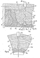
- a cylinder 1 as the first working member and a piston 2 as the second working member are connected to one another via a tubular sealing element 3, which is supported on a cylindrical support surface 4 of the first working member.
- the support surface 4 forms a toroidal outwardly curved transition surface section 4a.
- the connection area 3 a is integrally connected, for example by vulcanization, to an intermediate ring 1 a of the cylinder 1.
- the mouth of the lubricant supply which is yet to be explained, is located in this connection area.
- the sealing element is also integrally connected to a conical surface of the piston 2.
- a helical compression spring 2a presses the shaft 2b, which is displaceably guided in the cylinder 1, downward against an oscillating drive member, so that the working space 5 formed within the sealing element is reduced during a movement in accordance with arrow X.
- the piston 2 assumes its lowest position at the maximum working space volume.
- the work space is connected by a cover 6 with supply and discharge line 6a to a valve arrangement (not shown) for a mode of operation of the device as a pump.
- a gap-shaped lubricant space 3b of small radial thickness Between the sealing element 3 and the support wall 4 there is a gap-shaped lubricant space 3b of small radial thickness, the lubricant filling of which excludes contact between the sealing element and the support surface during the oscillating longitudinal expansion of the sealing element in accordance with the piston movement.
- a motor unit 7 with a drive shaft 7a and cams 7b As a drive for the piston movement, a motor unit 7 with a drive shaft 7a and cams 7b is provided, against which the latter of the piston shaft 2b is pressed by the compression spring 2a.
- a lubricant supply device is also coupled to the motor unit 7 with a pump 8 via a schematically indicated shaft 8a and a cam 8b.
- a check valve 8d can be inserted in the lubricant supply line 8c, but preferably the mouth 9 of the lubricant supply is provided with a low-inertia check valve member 15.
- the lubricant feed opening 9 is located on the underside of an annular body 10 provided with corresponding passage grooves, which forms the transition surface section 4a on its upper side.
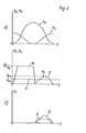
- the diagrams in FIG. 2 relate to an operation of the piston-cylinder arrangement as a pump, ie with a high working pressure with a decreasing working space volume.
- Diagram (a) shows the course of the stroke h of the working piston 2 and the pump stroke h Z of the lubricant supply pump over the time t. This method of operation corresponds to a synchronized lubricant supply in the working strokes with increasing work space volume.
- the associated course of the lubricant supply pressure p is indicated in curve B of diagram (b). This feed allows a comparatively low maximum supply pressure p Z1 .
- the time course of the lubricant volume flow v Z is indicated in curve B in diagram (c).
- an asynchronous lubricant supply can be used, for example with an essentially constant supply pressure p ZO according to line A in diagram (b).
- p ZO supply pressure
- a radial channel 11 in the cylinder 1 a circumferential distributor groove 12 on the ring body 10 and a plurality of radial feed grooves 13 within the end face 10a are connected to the feed line 8c.
- the radial feed grooves 13 open into an inner circumferential groove 14 between the ring body 10 and the cylinder 1, which acts as an end distributor for the lubricant supply into the gap 3b.
- the mouth 9 itself is formed by a circumferential groove with a flat, triangular cross section, into which an annular, radially deformable valve member 15 is inserted.
- the base side 15a of the ring cross section facing the sealing element 3 has a width b, which is dimensioned substantially larger than the radial cross-sectional height d, so that there are rear-side surfaces 15b of the ring which are inclined at an acute angle to the cylindrical part of the support surface 4.
- the annular valve member 15 is deformed radially inward, as is indicated by the broken line in FIG. 3a. This results in passage channels which open at an acute angle into the lubricant chamber 3b on the rear side surfaces 15b of the ring and which, when the working pressure predominates, close again automatically with radial expansion of the ring outward.
- the annular valve member can optionally be made of a deformation-resistant but comparatively flexible material, in particular of a sliding-friendly plastic, so that small pressure differences are sufficient for rapid valve actuation.
- the low mass of the annular valve member also contributes to a low-inertia function.
- annular valve member 15 On the outside of the annular valve member 15 is an annular extension 15c running in the circumferential direction provided that engages flush in the circumferential groove 14 and secures the valve member against axial displacement.
- recesses 15d are provided in the annular extension 15c, which engage radially inwards in the region of the rear side surfaces 15b.
- the lubricant can pass from the circumferential groove 14 into the passage channels formed on the rear side surfaces 15b in the case of radial inward deformation when the radial inward deformation has only reached a slight degree. This also contributes to a low-delay function of the check valve.
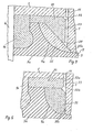
- a circumferential distributor groove 22 as well as radial channels 23 and an end distributor groove 24 adjoin the feed line 8c and the radial channel 11 within the right end face of an annular body 20.
- the transition surface section 4a forms an annular valve member 25, which is separated from the ring body 20 and is axially displaceable because of the deformability of the sealing element connection region 3a and which closes the lubricant supply opening with its rear surface 25a when the working pressure exceeds the lubricant supply pressure.
- the valve member 25 is axially displaced to the left in the sense of FIG. 4, the lower section of the rear surface 25a clears the passage into the lubricant chamber 3b. Again, there is an acute angle mouth of the lubricant flow with respect to the cylindrical part of the support surface 4, which contributes to a uniform and rapid distribution of the lubricant.
- the annular valve member 25 can, in addition to or if necessary, have a radial deformability in addition to its axial displacement, which can be easily achieved by appropriate choice of material.
- the cross section of the ring body can easily twist during the inward deformation in such a way that the inner edge region of the rear side surface 25a lifts off the cylinder, while the outer region of the ring continues to be supported. In this way, a slight deformation of the ring body is sufficient for the valve actuation.
- an axially displaceable, annular valve member 35 is provided, which rests with its right end face 35a in the flow state against a corresponding, flat end face of the cylinder 1 and is displaced to the left under the effect of the lubricant supply pressure for opening .
- the valve member is fitted radially into a spacer ring 36 which has circumferential distributor grooves 32a and 32b on its right end face and radial channels 33 for the passage of the lubricant to the right end face of the valve member 35.
- Such an implementation comes into play in particular also for the use of non-deformable, wear-resistant materials for the valve member 35.
Landscapes
- Engineering & Computer Science (AREA)
- Mechanical Engineering (AREA)
- General Engineering & Computer Science (AREA)
- Details Of Reciprocating Pumps (AREA)
- Sealing Devices (AREA)
- Lubrication Of Internal Combustion Engines (AREA)
- Sliding-Contact Bearings (AREA)
Priority Applications (1)
| Application Number | Priority Date | Filing Date | Title |
|---|---|---|---|
| AT80101491T ATE12044T1 (de) | 1979-04-06 | 1980-03-21 | Verfahren und einrichtung zur schmiermittelzufuehrung an einer kolbenzylinderanordnung. |
Applications Claiming Priority (2)
| Application Number | Priority Date | Filing Date | Title |
|---|---|---|---|
| CH326279A CH642145A5 (de) | 1979-04-06 | 1979-04-06 | Verfahren und einrichtung zur schmiermittelzufuehrung an einer kolben-zylinderanordnung. |
| CH3262/79 | 1979-04-06 |
Publications (3)
| Publication Number | Publication Date |
|---|---|
| EP0017100A2 true EP0017100A2 (fr) | 1980-10-15 |
| EP0017100A3 EP0017100A3 (en) | 1981-01-07 |
| EP0017100B1 EP0017100B1 (fr) | 1985-03-06 |
Family
ID=4252169
Family Applications (1)
| Application Number | Title | Priority Date | Filing Date |
|---|---|---|---|
| EP80101491A Expired EP0017100B1 (fr) | 1979-04-06 | 1980-03-21 | Procédé et dispositif de lubrification d'un arrangement piston et cylindre |
Country Status (15)
| Country | Link |
|---|---|
| US (1) | US4384510A (fr) |
| EP (1) | EP0017100B1 (fr) |
| JP (1) | JPS55139594A (fr) |
| AR (1) | AR223868A1 (fr) |
| AT (1) | ATE12044T1 (fr) |
| AU (1) | AU540832B2 (fr) |
| BR (1) | BR8002065A (fr) |
| CH (1) | CH642145A5 (fr) |
| CS (1) | CS258459B2 (fr) |
| DD (1) | DD150102A5 (fr) |
| DE (1) | DE3070250D1 (fr) |
| HU (1) | HU182116B (fr) |
| MX (1) | MX153130A (fr) |
| PL (1) | PL130978B1 (fr) |
| ZA (1) | ZA801966B (fr) |
Families Citing this family (8)
| Publication number | Priority date | Publication date | Assignee | Title |
|---|---|---|---|---|
| DE2914694C2 (de) | 1979-04-11 | 1980-09-11 | Hermann Hemscheidt Maschinenfabrik Gmbh & Co, 5600 Wuppertal | Zylinderkolben-Aggregat |
| JPS6022195B2 (ja) * | 1982-01-22 | 1985-05-31 | 義一 山谷 | 高圧流体発生装置 |
| DE102004027511A1 (de) * | 2004-06-04 | 2005-12-22 | Robert Bosch Gmbh | Leckagefreie Kolbenpumpe |
| DE102013014930A1 (de) * | 2013-09-11 | 2015-03-12 | Man Truck & Bus Ag | Steuerventil für eine Schmiermitteldüse |
| DE102020211264A1 (de) * | 2020-09-08 | 2022-03-10 | Aktiebolaget Skf | System zum Schmieren eines gedichteten Lagers und zugehöriges Verfahren |
| CN117307348A (zh) * | 2023-10-09 | 2023-12-29 | 含山县大力精密机械有限公司 | 一种发动机缸套润滑装置 |
| CN117329096A (zh) * | 2023-10-23 | 2024-01-02 | 太原理工大学 | 一种油-水全分离、自平衡式高压快响应高水基柱塞泵 |
| CN117231493A (zh) * | 2023-10-23 | 2023-12-15 | 太原理工大学 | 一种高压大流量高水基液压泵用柔性缸塞复合结构 |
Family Cites Families (14)
| Publication number | Priority date | Publication date | Assignee | Title |
|---|---|---|---|---|
| GB185815A (en) * | 1921-06-06 | 1922-09-06 | Haruo Hidaka | Improvements relating to stuffing boxes for compressor piston rods and the like, and to oil pressure supply apparatus therefor |
| US2027979A (en) * | 1934-07-14 | 1936-01-14 | Kellogg M W Co | Boot pump |
| US2191861A (en) * | 1939-01-12 | 1940-02-27 | Theodore R Rymal | Pump |
| US3212447A (en) * | 1962-10-23 | 1965-10-19 | Laval Turbine | Pumps |
| US3453995A (en) * | 1965-06-11 | 1969-07-08 | Mack Trucks | Piston cooling and lubrication system |
| DE1912171A1 (de) * | 1969-03-11 | 1970-11-12 | Voegele Ag J | Schmieranlage,insbesondere fuer die Hubtaktschmierung bei Kolbenmaschinen |
| NL6918558A (fr) * | 1969-11-11 | 1971-05-13 | ||
| US3685840A (en) * | 1971-03-29 | 1972-08-22 | Dresser Ind | Packing for compressors, pumps or the like |
| US3769879A (en) * | 1971-12-09 | 1973-11-06 | A Lofquist | Self-compensating diaphragm pump |
| US3902404A (en) * | 1972-01-29 | 1975-09-02 | Pumpenfabrik Urach | Sealing sleeve arrangement |
| CA1040065A (fr) | 1974-01-22 | 1978-10-10 | Quadrupol Ag | Ensemble cylindre et piston, particulierement pour usages a haute pression |
| DE2554733C3 (de) | 1974-12-17 | 1983-12-15 | Quadrupol AG, Glarus | Kolben-Zylinderanordnung mit Dichtungsschlauch |
| DE2621348C2 (de) * | 1976-05-14 | 1984-05-30 | M.A.N. Maschinenfabrik Augsburg-Nürnberg AG, 8500 Nürnberg | Zylinder mit trockener dünnwandiger Zylinderlaufbuchse für Brennkraftmaschinen |
| DE2747843C3 (de) * | 1977-10-26 | 1980-07-03 | Woma Apparatebau Wolfgang Maasberg & Co Gmbh, 4100 Duisburg | Kolbenpumpe, insbesondere Hochdruck-Kolbenpumpe in Liegendbauweise |
-
1979
- 1979-04-06 CH CH326279A patent/CH642145A5/de not_active IP Right Cessation
-
1980
- 1980-03-21 AT AT80101491T patent/ATE12044T1/de not_active IP Right Cessation
- 1980-03-21 EP EP80101491A patent/EP0017100B1/fr not_active Expired
- 1980-03-21 DE DE8080101491T patent/DE3070250D1/de not_active Expired
- 1980-03-31 AR AR280513A patent/AR223868A1/es active
- 1980-03-31 MX MX181798A patent/MX153130A/es unknown
- 1980-04-02 ZA ZA00801966A patent/ZA801966B/xx unknown
- 1980-04-02 BR BR8002065A patent/BR8002065A/pt not_active IP Right Cessation
- 1980-04-02 HU HU80790A patent/HU182116B/hu unknown
- 1980-04-03 AU AU57171/80A patent/AU540832B2/en not_active Expired
- 1980-04-03 US US06/136,500 patent/US4384510A/en not_active Expired - Lifetime
- 1980-04-03 DD DD80220214A patent/DD150102A5/de not_active IP Right Cessation
- 1980-04-04 CS CS802357A patent/CS258459B2/cs unknown
- 1980-04-05 PL PL1980223294A patent/PL130978B1/pl unknown
- 1980-04-05 JP JP4511280A patent/JPS55139594A/ja active Granted
Also Published As
| Publication number | Publication date |
|---|---|
| DD150102A5 (de) | 1981-08-12 |
| US4384510A (en) | 1983-05-24 |
| ATE12044T1 (de) | 1985-03-15 |
| EP0017100A3 (en) | 1981-01-07 |
| CH642145A5 (de) | 1984-03-30 |
| AU5717180A (en) | 1980-10-09 |
| EP0017100B1 (fr) | 1985-03-06 |
| DE3070250D1 (en) | 1985-04-11 |
| BR8002065A (pt) | 1980-11-25 |
| ZA801966B (en) | 1981-04-29 |
| PL130978B1 (en) | 1984-09-29 |
| AR223868A1 (es) | 1981-09-30 |
| PL223294A1 (fr) | 1981-01-16 |
| AU540832B2 (en) | 1984-12-06 |
| JPS6365829B2 (fr) | 1988-12-16 |
| CS258459B2 (en) | 1988-08-16 |
| JPS55139594A (en) | 1980-10-31 |
| HU182116B (en) | 1983-12-28 |
| MX153130A (es) | 1986-08-08 |
Similar Documents
| Publication | Publication Date | Title |
|---|---|---|
| DE2503346C2 (de) | Kraftstoffverteilereinspritzpumpe für Brennkraftmaschinen | |
| DE2516810B2 (de) | Mit Druckflüssigkeit betriebener Schlagapparat | |
| DE2608791C2 (fr) | ||
| DE2353737A1 (de) | Kraftstoffeinspritzpumpe fuer brennkraftmaschinen | |
| EP0017100B1 (fr) | Procédé et dispositif de lubrification d'un arrangement piston et cylindre | |
| DE2740879C2 (fr) | ||
| DE1476247A1 (de) | Kraftstoffeinspritzvorrichtung fuer mit Kraftstoffeinspritzung und Kompressionszuendung arbeitende Brennkraftmaschinen | |
| DE102007000095B4 (de) | Kraftstoffeinspritzelement | |
| DE102018208352A1 (de) | Hydraulische Spülventilanordnung | |
| DE3416041A1 (de) | Progressivverteiler fuer schmiermittel | |
| AT392122B (de) | Kraftstoffeinspritzpumpe fuer brennkraftmaschinen | |
| DE2922332C2 (de) | Brennstoffeinspritzvorrichtung für Brennkraftmaschinen | |
| CH654377A5 (en) | Cylinder and piston lubrication device on an internal combustion engine | |
| EP0051728A1 (fr) | Dispositif de commande pour un vérin hydraulique | |
| DE3425816A1 (de) | Kraftstoffeinspritzduese | |
| DE69500259T2 (de) | Kraftstoffeinspritzventil für eine brennkraftmaschine | |
| DE3048229C2 (de) | Rückschlagventil für Grubenausbaustempel | |
| DE2650368A1 (de) | Verfahren zur ausgestaltung des kolbens einer brennstoffeinspritzpumpe einer brennkraftmaschine und so erzielter kolben | |
| DE2308146C2 (de) | Steuereinrichtung für den Hubzylinder einer Schlepperhydraulik | |
| DE2028321C2 (de) | Kraftstoffeinspritzpumpe für Brennkraftmaschinen | |
| DE3508170A1 (de) | Hydraulische vorrichtung | |
| DE3334619C2 (de) | Kraftstoffeinspritzeinrichtung | |
| DE3225131A1 (de) | Kraftstoffeinspritzduese | |
| AT232793B (de) | Doppelstempelbrennstoffpumpe | |
| AT224403B (de) | Zuteilelement |
Legal Events
| Date | Code | Title | Description |
|---|---|---|---|
| PUAI | Public reference made under article 153(3) epc to a published international application that has entered the european phase |
Free format text: ORIGINAL CODE: 0009012 |
|
| AK | Designated contracting states |
Designated state(s): AT BE CH DE FR GB IT LU NL SE |
|
| PUAL | Search report despatched |
Free format text: ORIGINAL CODE: 0009013 |
|
| AK | Designated contracting states |
Designated state(s): AT BE CH DE FR GB IT LU NL SE |
|
| 17P | Request for examination filed |
Effective date: 19810414 |
|
| ITF | It: translation for a ep patent filed | ||
| GRAA | (expected) grant |
Free format text: ORIGINAL CODE: 0009210 |
|
| AK | Designated contracting states |
Designated state(s): AT BE CH DE FR GB IT LU NL SE |
|
| REF | Corresponds to: |
Ref document number: 12044 Country of ref document: AT Date of ref document: 19850315 Kind code of ref document: T |
|
| REF | Corresponds to: |
Ref document number: 3070250 Country of ref document: DE Date of ref document: 19850411 |
|
| ET | Fr: translation filed | ||
| PLBE | No opposition filed within time limit |
Free format text: ORIGINAL CODE: 0009261 |
|
| STAA | Information on the status of an ep patent application or granted ep patent |
Free format text: STATUS: NO OPPOSITION FILED WITHIN TIME LIMIT |
|
| 26N | No opposition filed | ||
| ITTA | It: last paid annual fee | ||
| EPTA | Lu: last paid annual fee | ||
| EAL | Se: european patent in force in sweden |
Ref document number: 80101491.1 |
|
| PGFP | Annual fee paid to national office [announced via postgrant information from national office to epo] |
Ref country code: FR Payment date: 19990128 Year of fee payment: 20 |
|
| PGFP | Annual fee paid to national office [announced via postgrant information from national office to epo] |
Ref country code: BE Payment date: 19990208 Year of fee payment: 20 |
|
| PGFP | Annual fee paid to national office [announced via postgrant information from national office to epo] |
Ref country code: LU Payment date: 19990308 Year of fee payment: 20 |
|
| PGFP | Annual fee paid to national office [announced via postgrant information from national office to epo] |
Ref country code: GB Payment date: 19990315 Year of fee payment: 20 Ref country code: AT Payment date: 19990315 Year of fee payment: 20 |
|
| PGFP | Annual fee paid to national office [announced via postgrant information from national office to epo] |
Ref country code: SE Payment date: 19990317 Year of fee payment: 20 |
|
| PGFP | Annual fee paid to national office [announced via postgrant information from national office to epo] |
Ref country code: NL Payment date: 19990331 Year of fee payment: 20 |
|
| PGFP | Annual fee paid to national office [announced via postgrant information from national office to epo] |
Ref country code: DE Payment date: 19990519 Year of fee payment: 20 |
|
| PGFP | Annual fee paid to national office [announced via postgrant information from national office to epo] |
Ref country code: CH Payment date: 19990625 Year of fee payment: 20 |
|
| BE20 | Be: patent expired |
Free format text: 20000321 *HYDROWATT SYSTEMS LTD |
|
| PG25 | Lapsed in a contracting state [announced via postgrant information from national office to epo] |
Ref country code: GB Free format text: LAPSE BECAUSE OF EXPIRATION OF PROTECTION Effective date: 20000320 Ref country code: CH Free format text: LAPSE BECAUSE OF EXPIRATION OF PROTECTION Effective date: 20000320 |
|
| PG25 | Lapsed in a contracting state [announced via postgrant information from national office to epo] |
Ref country code: NL Free format text: LAPSE BECAUSE OF EXPIRATION OF PROTECTION Effective date: 20000321 Ref country code: LU Free format text: LAPSE BECAUSE OF NON-PAYMENT OF DUE FEES Effective date: 20000321 Ref country code: AT Free format text: LAPSE BECAUSE OF EXPIRATION OF PROTECTION Effective date: 20000321 |
|
| PG25 | Lapsed in a contracting state [announced via postgrant information from national office to epo] |
Ref country code: SE Free format text: THE PATENT HAS BEEN ANNULLED BY A DECISION OF A NATIONAL AUTHORITY Effective date: 20000330 |
|
| REG | Reference to a national code |
Ref country code: GB Ref legal event code: PE20 Effective date: 20000320 |
|
| REG | Reference to a national code |
Ref country code: CH Ref legal event code: PL |
|
| EUG | Se: european patent has lapsed |
Ref document number: 80101491.1 |
|
| NLV7 | Nl: ceased due to reaching the maximum lifetime of a patent |
Effective date: 20000321 |