EP0017640A2 - Quecksilberbenetzter Miniaturschutzgasschalter - Google Patents
Quecksilberbenetzter Miniaturschutzgasschalter Download PDFInfo
- Publication number
- EP0017640A2 EP0017640A2 EP80870018A EP80870018A EP0017640A2 EP 0017640 A2 EP0017640 A2 EP 0017640A2 EP 80870018 A EP80870018 A EP 80870018A EP 80870018 A EP80870018 A EP 80870018A EP 0017640 A2 EP0017640 A2 EP 0017640A2
- Authority
- EP
- European Patent Office
- Prior art keywords
- capsule
- armature
- mercury
- blade
- switch according
- Prior art date
- Legal status (The legal status is an assumption and is not a legal conclusion. Google has not performed a legal analysis and makes no representation as to the accuracy of the status listed.)
- Granted
Links
Images


Classifications
-
- H—ELECTRICITY
- H01—ELECTRIC ELEMENTS
- H01H—ELECTRIC SWITCHES; RELAYS; SELECTORS; EMERGENCY PROTECTIVE DEVICES
- H01H1/00—Contacts
- H01H1/06—Contacts characterised by the shape or structure of the contact-making surface, e.g. grooved
- H01H1/08—Contacts characterised by the shape or structure of the contact-making surface, e.g. grooved wetted with mercury
-
- H—ELECTRICITY
- H01—ELECTRIC ELEMENTS
- H01H—ELECTRIC SWITCHES; RELAYS; SELECTORS; EMERGENCY PROTECTIVE DEVICES
- H01H1/00—Contacts
- H01H1/64—Protective enclosures, baffle plates, or screens for contacts
- H01H1/66—Contacts sealed in an evacuated or gas-filled envelope, e.g. magnetic dry-reed contacts
Definitions
- the present invention relates to a back-and-forth type mercury reed switch, that is to say which interrupts one circuit before establishing another.
- This type of switch is also called a Form C switch.
- a mercury blade switch includes a blade armature whose base is immersed in a cup containing mercury and whose free end is capable of moving between two fixed contacts.
- the effect of this capillarity allows the mercury to spread over the surface of the blade, thus wetting the cooperating surfaces of the armature and the fixed contacts. It thus really establishes a mercury-mercury contact having a very low contact resistance.
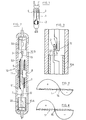
- FIG. 1 The prior art of a back-and-forth type mercury capsule is illustrated by the drawing of Figure 1.
- the frame is formed by a cantilever blade 1 fixed at its lower end in the cup of mercury 2.
- the armature 1 is adjusted to a neutral position between the contacts 3 and 4 so that the armature behaves like a spring without initial pressure.
- the normally closed state is obtained using a permanent magnet P fixed externally near the contacts.
- a switch is made that can work either in normal monostable mode (the armature returning to its initial position after removal of the excitation), or in bistable mode (the armature returning to its initial position only response to reverse excitation).
- the P relay is placed to create a bistable mode.
- the function of the armature is to provide sufficient mechanical tilting force around an actual fixed pivot point.
- the disadvantage of such a capsule is that the switch can only work if the capsule is used in a vertical position, which limits its use applications where this condition is met.
- a mercury capsule of this kind can hardly be miniaturized and is relatively expensive.
- the problem which the invention aims to solve is to produce a miniature mercury switch designed to be able to be used in any position.
- the mercury blade switch comprises a capsule containing an armature consisting of a blade of magnetic material terminated at its ends by two pole pieces capable of coming to bond alternately each against a separate fixed contact when the armature switches over.
- the frame is suspended at the ends of a helical spring which extends axially around the blade of the frame and which is fixed inside the capsule by means of a cylindrical annular electrode attached to the part center of the spring.
- a film of mercury wets the surface of the armature, the spring, the inner surface of the annular electrode and the surface of the contacts.
- a mercury capsule according to the invention can be used with advantages in all applications where a long service life, high reliability and / or the possibility of working in any position is required, for example: test equipment, military equipment, telecommunications equipment and more particularly subscriber equipment, industrial process control equipment.
- the armature 1 has a central part in the form of a blade 11 and two pole ends 12 and 13.
- the fixed contacts 2 and 3 are situated at the opposite ends of the armature 1 so that each of the poles 12, 13 of the armature is capable of bonding alternately against one of the contacts 2,3 when the armature rocks.
- the frame is made of a magnetic material, for example Permalloy or Crovar (product of the company Vacuumschmelze GmbH, Hanau, RFA).
- the frame 1 is suspended from the ends of a helical spring 5 extending longitudinally around the central part 11 of the frame.
- the suspension points 51 and 52 of the frame 1 are arranged symmetrically with respect to the middle of the length of the frame.
- the spring 5 is made to work on bending.
- the spring 5 is fixed at its central part inside a metallic cylindrical ring 6 kept fixed inside the sealed capsule 10.
- the ring 6 serves as a central electrode.
- the capsule is provided with external connections for the contacts 2 and 3 and for the central electrode 6.
- the capsule 10 is formed by two glass tubes 10A, 10B arranged in alignment with a spacing between them, the annular electrode 6 being located symmetrically with respect to the pivot point of the frame 1.
- the fixed contacts 2 and 3 are surrounded by metal tubes 20 and 30 serving as magnetic shunts.
- the internal wall of the tubes 20 and 30, the surface of the armature 1, the spring 5, the internal surface of the annular electrode 6 and the surface of the contacts 2 and 3 are wetted with a film of mercury.
- the cooperating surfaces of the poles 12 and 13 and of the fixed contacts 2 and 3 are lined with pellets of a material which cannot be wetted by mercury, for example chromium oxide. These pellets are denoted 7 in the view of FIG. 3. They must have a sufficiently small surface so that, when the reinforcement 1 tips over, the mercury which spurts from the contact zone is quickly replaced because otherwise the high frequency switching will would find it more difficult. Poles 12 and 13 of the armature must on the other hand have a large enough surface so that a too large drop of mercury which would be projected against the wall of the capsule can be sucked by said poles.
- the capsule as described above must be supplemented with an excitation coil as is well known in the art.
- an excitation coil as is well known in the art.
- FIG. 4A the operation of the switch according to the invention is illustrated in Figures 4 A / D on which the excitation coil has not been shown
- FIG. 4A the armature 1 is shown in the position in which its pole 12 sticks against the contact 2, leaving its pole 13 detached from the contact 3
- the initial state of imbalance is created by one of the means which will be described later.
- the left and right marginal parts of the spring 5 are subjected to a certain bending moment due to the initial state of imbalance and these marginal parts therefore store a certain mechanical energy.
- the initial state of imbalance is created by magnetic means which will be described in the following with reference to FIGS. 5 to 8.
- FIGS. 5 and 6 are illustrated two examples of embodiment using external permanent magnets to create the initial state.
- two permanent magnets 21 and 22 are externally fixed on the capsule 10.
- the strength and the position of the magnets relative to the pivot point of the armature are chosen and adapted according to the mode of desired operation.
- two magnets of unequal forces will be chosen which are arranged symmetrically with respect to the pivot point of the armature or two equal magnets located at different distances from the pivot point.
- An annular permanent magnet could also be provided in an off-center position relative to the transverse axis of the capsule.
- FIG. 6 illustrates such an embodiment: the annular permanent magnet is designated by 23.
- the external connection with the annular electrode 6 is ensured by means of a sheet of electrically conductive material 24 placed on the surface outside of the glass tubes 10A and 10B.
- the initial magnetic state can also be created without the addition of external permanent magnets, by polarizing the armature so that it itself constitutes a permanent magnet.
- Figures 7 and 8 graphically illustrate the polarization profiles of the armature 1 to achieve monostable and bistable operating modes.
- the armature 1 is polarized in opposite directions on either side of a section 14 that is offset from the middle section.
- the bistable mode (FIG. 8) the armature is polarized in opposite directions on either side of the middle section 15.
- the annular electrode is generally connected to ground.
- the small dimensions that can be given to the mercury capsule according to the invention allow one or more mercury capsules and the excitation coil to be housed in a protective housing provided with pins for external connections, thus providing a component. with miniature mercury as illustrated by way of example in FIG. 9.
- This drawing shows a capsule 10 and the excitation coil 40 which surrounds it, housed inside the housing 50 mounted on a base 60 of where the connection pins 70 emerge.
- the reference 80 designates a filling material.
Landscapes
- Contacts (AREA)
- Electromagnets (AREA)
- Switches That Are Operated By Magnetic Or Electric Fields (AREA)
Priority Applications (1)
| Application Number | Priority Date | Filing Date | Title |
|---|---|---|---|
| AT80870018T ATE4399T1 (de) | 1979-03-15 | 1980-03-14 | Quecksilberbenetzter miniaturschutzgasschalter. |
Applications Claiming Priority (2)
| Application Number | Priority Date | Filing Date | Title |
|---|---|---|---|
| LU81053A LU81053A1 (fr) | 1979-03-15 | 1979-03-15 | Commutateur a lame au mercure minature |
| LU81053 | 1979-03-15 |
Publications (3)
| Publication Number | Publication Date |
|---|---|
| EP0017640A2 true EP0017640A2 (de) | 1980-10-15 |
| EP0017640A3 EP0017640A3 (en) | 1980-11-26 |
| EP0017640B1 EP0017640B1 (de) | 1983-08-03 |
Family
ID=19729123
Family Applications (1)
| Application Number | Title | Priority Date | Filing Date |
|---|---|---|---|
| EP80870018A Expired EP0017640B1 (de) | 1979-03-15 | 1980-03-14 | Quecksilberbenetzter Miniaturschutzgasschalter |
Country Status (5)
| Country | Link |
|---|---|
| EP (1) | EP0017640B1 (de) |
| JP (1) | JPS55143717A (de) |
| AT (1) | ATE4399T1 (de) |
| DE (1) | DE3064469D1 (de) |
| LU (1) | LU81053A1 (de) |
Cited By (2)
| Publication number | Priority date | Publication date | Assignee | Title |
|---|---|---|---|---|
| GB2131230A (en) * | 1982-10-07 | 1984-06-13 | Weston William A | Electric switching devices |
| FR2620821A1 (fr) * | 1987-09-17 | 1989-03-24 | Inst Francais Du Petrole | Dispositif indicateur de tension entre un organe et un element de liaison |
Families Citing this family (1)
| Publication number | Priority date | Publication date | Assignee | Title |
|---|---|---|---|---|
| JP2685746B2 (ja) * | 1986-10-06 | 1997-12-03 | 日本ヒユーレツト・パツカード 株式会社 | 低雑音水銀スイツチ |
Family Cites Families (4)
| Publication number | Priority date | Publication date | Assignee | Title |
|---|---|---|---|---|
| US3380006A (en) * | 1964-08-11 | 1968-04-23 | Fifth Dimension Inc | Logic circuits |
| US3643185A (en) * | 1970-10-05 | 1972-02-15 | Gen Electric | Mercury-wetted relay and method of manufacture |
| FR2242765A1 (de) * | 1973-08-31 | 1975-03-28 | Gillard Michel | |
| SE388713B (sv) * | 1974-08-22 | 1976-10-11 | Mo Energeticheskij Institut | Tungrele |
-
1979
- 1979-03-15 LU LU81053A patent/LU81053A1/fr unknown
-
1980
- 1980-03-14 JP JP3330980A patent/JPS55143717A/ja active Pending
- 1980-03-14 DE DE8080870018T patent/DE3064469D1/de not_active Expired
- 1980-03-14 EP EP80870018A patent/EP0017640B1/de not_active Expired
- 1980-03-14 AT AT80870018T patent/ATE4399T1/de active
Cited By (2)
| Publication number | Priority date | Publication date | Assignee | Title |
|---|---|---|---|---|
| GB2131230A (en) * | 1982-10-07 | 1984-06-13 | Weston William A | Electric switching devices |
| FR2620821A1 (fr) * | 1987-09-17 | 1989-03-24 | Inst Francais Du Petrole | Dispositif indicateur de tension entre un organe et un element de liaison |
Also Published As
| Publication number | Publication date |
|---|---|
| LU81053A1 (fr) | 1980-09-24 |
| DE3064469D1 (en) | 1983-09-08 |
| EP0017640A3 (en) | 1980-11-26 |
| ATE4399T1 (de) | 1983-08-15 |
| JPS55143717A (en) | 1980-11-10 |
| EP0017640B1 (de) | 1983-08-03 |
Similar Documents
| Publication | Publication Date | Title |
|---|---|---|
| FR2815461A1 (fr) | Dispositif de commutation | |
| FR2742917A1 (fr) | Dispositif miniature pour executer une fonction predeterminee, notamment microrelais | |
| EP1743346B1 (de) | Überspannungsschutzeinrichtung mit lichtbogenlöschelementen | |
| EP0174238B1 (de) | Monostabil oder bistabil arbeitender polarisierter Elektromagnet | |
| CA1249622A (fr) | Appareil disjoncteur a ouverture et fermeture telecommandees de ses circuits | |
| EP0017640B1 (de) | Quecksilberbenetzter Miniaturschutzgasschalter | |
| FR2827075A1 (fr) | Appareillage electrique de coupure et de sectionnement comportant une ampoule sous vide | |
| FR2815463A1 (fr) | Dispositif de commutation a attenuation de chocs | |
| EP3261105B1 (de) | Elektrisches gerät zum leitungsschutz | |
| FR2736201A1 (fr) | Relais electromagnetique | |
| EP0032331A1 (de) | Schalter mit benetzten Kontakten und magnetischer Steuerung und elektrisches Relais mit einem solchen Schalter | |
| CH667942A5 (fr) | Appareil interrupteur protege contre les courants de court-circuit. | |
| EP0130208B1 (de) | Schalter mit bedientem öffnen und schliessen und mit automatischer öffnung im fall eines überstromes | |
| FR2511186A1 (fr) | Commutateur a deplacement rectiligne | |
| EP0036815B1 (de) | Lagerungsvorrichtung für ein auf seiner Basis schwenkbares bewegbares Blatt und Schalter mit einer solchen Vorrichtung | |
| EP0057130B1 (de) | Quecksilberschalter mit Rückstellung des beweglichen Elements durch die Oberflächenspannung des Quecksilbers | |
| FR2590074A1 (fr) | Interrupteur de circuit sous vide a basse tension | |
| FR2605796A1 (fr) | Disjoncteur electrique a arc tournant | |
| EP0693765A1 (de) | Elektromagnetischer Auslöser für einen Niederspannungsschutzschalter | |
| WO1984000442A1 (fr) | Interrupteur electrique a ressort de contact prearme | |
| US4329670A (en) | Mercury reed switch | |
| EP2827352B1 (de) | Schutzschalter und Herstellungsverfahren eines Schutzschalters | |
| FR2574985A1 (fr) | Micro-interrupteur | |
| FR3093227A1 (fr) | Dispositif de commande de contacts d’une ampoule à vide pour appareil de connexion électrique | |
| JPH11144575A (ja) | 真空インタラプタ及びその製造方法 |
Legal Events
| Date | Code | Title | Description |
|---|---|---|---|
| PUAI | Public reference made under article 153(3) epc to a published international application that has entered the european phase |
Free format text: ORIGINAL CODE: 0009012 |
|
| PUAL | Search report despatched |
Free format text: ORIGINAL CODE: 0009013 |
|
| AK | Designated contracting states |
Designated state(s): AT BE CH DE FR GB IT NL SE |
|
| AK | Designated contracting states |
Designated state(s): AT BE CH DE FR GB IT NL SE |
|
| 17P | Request for examination filed |
Effective date: 19810427 |
|
| ITF | It: translation for a ep patent filed | ||
| GRAA | (expected) grant |
Free format text: ORIGINAL CODE: 0009210 |
|
| AK | Designated contracting states |
Designated state(s): AT BE CH DE FR GB IT NL SE |
|
| PG25 | Lapsed in a contracting state [announced via postgrant information from national office to epo] |
Ref country code: NL Effective date: 19830803 |
|
| REF | Corresponds to: |
Ref document number: 4399 Country of ref document: AT Date of ref document: 19830815 Kind code of ref document: T |
|
| PG25 | Lapsed in a contracting state [announced via postgrant information from national office to epo] |
Ref country code: AT Effective date: 19830901 |
|
| REF | Corresponds to: |
Ref document number: 3064469 Country of ref document: DE Date of ref document: 19830908 |
|
| NLV1 | Nl: lapsed or annulled due to failure to fulfill the requirements of art. 29p and 29m of the patents act | ||
| PG25 | Lapsed in a contracting state [announced via postgrant information from national office to epo] |
Ref country code: SE Effective date: 19840315 |
|
| PG25 | Lapsed in a contracting state [announced via postgrant information from national office to epo] |
Ref country code: CH Effective date: 19840331 Ref country code: BE Effective date: 19840331 |
|
| PLBE | No opposition filed within time limit |
Free format text: ORIGINAL CODE: 0009261 |
|
| STAA | Information on the status of an ep patent application or granted ep patent |
Free format text: STATUS: NO OPPOSITION FILED WITHIN TIME LIMIT |
|
| 26N | No opposition filed | ||
| BERE | Be: lapsed |
Owner name: CP CLARE INTERNATIONAL N.V. Effective date: 19840314 |
|
| GBPC | Gb: european patent ceased through non-payment of renewal fee | ||
| GBPC | Gb: european patent ceased through non-payment of renewal fee | ||
| PG25 | Lapsed in a contracting state [announced via postgrant information from national office to epo] |
Ref country code: FR Free format text: LAPSE BECAUSE OF NON-PAYMENT OF DUE FEES Effective date: 19841130 |
|
| REG | Reference to a national code |
Ref country code: CH Ref legal event code: PL |
|
| PG25 | Lapsed in a contracting state [announced via postgrant information from national office to epo] |
Ref country code: DE Effective date: 19841201 |
|
| REG | Reference to a national code |
Ref country code: FR Ref legal event code: ST |
|
| PG25 | Lapsed in a contracting state [announced via postgrant information from national office to epo] |
Ref country code: GB Effective date: 19881118 |
|
| EUG | Se: european patent has lapsed |
Ref document number: 80870018.1 Effective date: 19850529 |
|
| P01 | Opt-out of the competence of the unified patent court (upc) registered |
Effective date: 20230522 |