EP0017877A1 - Dispositif d'avance à roues planétaires pour fils à souder par fusion - Google Patents
Dispositif d'avance à roues planétaires pour fils à souder par fusion Download PDFInfo
- Publication number
- EP0017877A1 EP0017877A1 EP80101826A EP80101826A EP0017877A1 EP 0017877 A1 EP0017877 A1 EP 0017877A1 EP 80101826 A EP80101826 A EP 80101826A EP 80101826 A EP80101826 A EP 80101826A EP 0017877 A1 EP0017877 A1 EP 0017877A1
- Authority
- EP
- European Patent Office
- Prior art keywords
- bearing part
- welding wire
- clamping piece
- feed according
- planet
- Prior art date
- Legal status (The legal status is an assumption and is not a legal conclusion. Google has not performed a legal analysis and makes no representation as to the accuracy of the status listed.)
- Granted
Links
- 238000003466 welding Methods 0.000 title claims abstract description 38
- 125000006850 spacer group Chemical group 0.000 claims description 5
- 238000006073 displacement reaction Methods 0.000 claims description 4
- 230000008018 melting Effects 0.000 claims description 3
- 238000002844 melting Methods 0.000 claims description 3
- 230000000284 resting effect Effects 0.000 claims 1
- 238000004519 manufacturing process Methods 0.000 description 3
- 238000010276 construction Methods 0.000 description 2
- 239000000256 polyoxyethylene sorbitan monolaurate Substances 0.000 description 2
- 238000003780 insertion Methods 0.000 description 1
- 230000037431 insertion Effects 0.000 description 1
Images


Classifications
-
- B—PERFORMING OPERATIONS; TRANSPORTING
- B23—MACHINE TOOLS; METAL-WORKING NOT OTHERWISE PROVIDED FOR
- B23K—SOLDERING OR UNSOLDERING; WELDING; CLADDING OR PLATING BY SOLDERING OR WELDING; CUTTING BY APPLYING HEAT LOCALLY, e.g. FLAME CUTTING; WORKING BY LASER BEAM
- B23K9/00—Arc welding or cutting
- B23K9/12—Automatic feeding or moving of electrodes or work for spot or seam welding or cutting
- B23K9/133—Means for feeding electrodes, e.g. drums, rolls, motors
- B23K9/1336—Driving means
Definitions
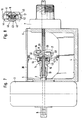
- the invention relates to a planetary gear feed for melting welding wires with at least two planet wheels, the axes of which form an angle with the welding wire axis, which are arranged radially with respect to the welding wire on a bearing part rotating about it and driven by the motor shaft and can be pressed against the welding wire under prestress.
- a linear drive of the type mentioned above is known for example from DE-PS 20 55 721.
- the planet gears rest under pressure on the surface of the wire and rotate in a plane perpendicular to the axis of rotation. Since the planet gears form an angle with the wire axis, the wire is advanced through the rotating planet gears.
- the wheel holders of the known planetary gear feed designed as pistons are supported on a conical cylindrical surface of a clamping nut which can be rotated around the welding wire.
- the clamping nut is axial slidable in the direction of the wire axis. This achieves a uniform infeed of the planet gears by 'a single clamping nut.
- the invention has for its object to provide a planetary gear feed of the type mentioned so that it is extremely simple in construction and thus inexpensive to manufacture and requires little effort for setting the planet gears.
- the bearing part consists of a sleeve slotted over the essential part of its length in the axial direction, that on each part of the slotted end of the bearing part a planet gear is and that the infeed of the bearing part and thus the planet gears takes place by axial displacement of the bearing part relative to a clamping piece enclosing it.
- the clamping piece consists of an adjusting ring, the infeed of the planet gears taking place by reducing the diameter of the adjusting ring.
- a planetary gear feed according to the invention is inexpensive to manufacture due to its simple structure, so that it is economically justifiable to use a planetary gear feed only for a narrowly limited diameter range.
- the exchange of the entire planetary gear advance when changing the welding wire thickness is then more cost-effective than the time-consuming adjustment of the planetary gear advance to the new welding wire thickness.
- a planetary gear feed according to the invention is set in the factory to a specific welding wire diameter range. The user no longer needs to make any settings.
- the clamping piece advantageously has a defined inner bore and the bearing piece, more precisely the part of the bearing piece forming a clamping sleeve, has a defined outer diameter.
- the adjusting ring can be selected in order to facilitate the adjustment in such a way that the desired contact pressure of the planet gears on the welding wire is reached with the maximum possible delivery.
- a linear drive 1 is attached to the motor shaft 2 of a motor 3.
- the motor 3 itself is screwed to a U-shaped flange 4, through the opening 5 of which the motor shaft 2 engages.
- the connector 7 for a hose package, not shown, is attached, at the end of which a welding gun is attached in a known manner.
- the welding wire (not shown) to be transported with the aid of the linear drive or the planetary gear feeder 1 is introduced via an insertion piece 8 into the hollow motor shaft 2 and from there it enters a nozzle 9 inserted into the motor shaft 2.
- the nozzle has a collar 34 and is held by means of a bearing part 10.
- the bearing part 10 is screwed onto a reduced and threaded end piece 11 of the motor shaft 2 and thus connected to it in a rotationally fixed manner.
- the bearing part 10 is provided with a bore 12 which receives the nozzle 9 and passes through the bearing part and which is substantially larger than is necessary for receiving the nozzle 9.
- the bearing part 10 is provided in its front area in the axial direction over a considerable part of its length with a slot 13, whereby the bearing part 10 is divided in its front area in the form of a slotted sleeve into two halves 14 and 15.
- the planet gear 16 and on the half 15 the planet gear 17 is rotatably mounted on axes 18.
- the planet gears 16 and 17 are thus rotatably connected to the bracket 10 and thus to the motor shaft 2.
- a thread 20 is attached on the outside of the other end 19 of the bearing part 10.
- a clamping piece 21 is pushed axially displaceably over this thread, which is held by means of a nut 22 which is screwed onto the thread 20 of the bearing part.
- the clamping piece 21 has a defined inner bore, which is determined by a ring 24 inserted into a bore 23 of the clamping piece.
- the outer surface of the bearing piece 10 is conical in the region of the slot 13, so that when moving the bearing piece 21 in the direction of the planet gears 16, 17, the two halves 14, 15 of the bearing part are pressed together. Since on these halves the planet gears 16, 17 are fastened with their axes 18, they are simultaneously moved towards one another and, if a welding wire is inserted, pressed against the surface thereof. The contact pressure can thus be finely adjusted relative to one another by the relative displacement of the clamping piece 21 and the bearing part 10.
- a sleeve 26 is fastened by means of two screws 25 and is closed by a plate 27.
- a bearing 28 is inserted, the inside diameter of which is selected such that it receives an inlet nozzle 29, the end 30, as well as the end 31, of the nozzle 9 ending as close as possible in the region of the planet gears 16, 17.
- the exemplary embodiment of a linear drive 1 shown in FIGS. 3 and 4 differs from the one described above essentially in the design of the bore 23 in the clamping piece 21 and in the design of the surface of the slotted part of the bearing part 10.
- the clamping piece 21 is provided in the embodiment of FIGS. 3 and 4 with a smooth bore 23, which have a very specific diameter corresponding to a wire diameter range.
- the surface of the camp partly 10 is cylindrical.
- the bearing part has a stop 37 which bears against the clamping piece 21 when the required distance between the planet gears 16, 17 is reached.
- the stop 37 would also ensure the exact setting of the planet gears in this case. To set this, in both cases the screw 22 would only have to be tightened until the bearing part 10 abuts the clamping piece 21 with its stop 37.
- FIGS. 5 and 6 differs from the previous ones essentially in that the clamping piece 21 is designed as an adjusting ring.
- This collar 21 can be seen in Fig. 6. This is pressed together in a known manner with the aid of a screw 38.
- the setting of the linear drive is made considerably easier if the inner diameter of the adjusting ring 21 with the screw 38 fully tightened, i. that is, when the slot 32 becomes zero, corresponds to the required setting of the linear drive.
- 5 shows, the inner bore of the collar 21 is slightly conical and engages in an undercut 35 in the bearing part 10, whereby a secure hold of the collar 21 is obtained.
- the inlet nozzle 29 is only held in the wall 6 of the flange 4.
- the front end of the inlet nozzle 29 could also be held in a further bearing 28 in this exemplary embodiment, which would be arranged similarly to the previously shown exemplary embodiments.
- the flange 4 is closed to the outside by a cover 36.
- linear drives according to the invention are set at the factory to a very specific wire diameter, so that no adjustment work is carried out during operation.
- the spring travel for the planet gears is very small, threading a new wire into the linear drive can be done without any particular difficulties.
- the planetary rollers are pushed apart by the wire. A linear drive according to the invention therefore does not require any adjustment work by the user.
- the clamping piece consists of a spacer sleeve 40 which has an internal thread into which two screws 41 and 42 can be screwed.
- the spacer sleeve 40 is inserted in a radial bore 43 of the bearing part 10 which extends through the two halves 14 and 15 of the bearing part 10.
- the bore 43 widens to a larger bore 44 and 45, the head of the screws 41 and 42 being chosen so large that this rests on the halves 14, 15 of the bearing part.
- the spacer sleeve 40 has a central bore 46 through which the welding wire to be transported, including the nozzle 9, engages.
- the delivery of the planetary gears 16 and 17 is performed by screwing the screws 41, 42 in the threaded spacer sleeve 4 0th As a result, the halves 14, 15 of the bearing part 10 are pressed together by the screw heads 41, 42 until the planet gears 16, 17 rest on the welding wire with the required pressure. This ensures that this is maintained even at high speeds.
Landscapes
- Engineering & Computer Science (AREA)
- Physics & Mathematics (AREA)
- Plasma & Fusion (AREA)
- Mechanical Engineering (AREA)
- Wire Processing (AREA)
- Arc Welding In General (AREA)
- Guides For Winding Or Rewinding, Or Guides For Filamentary Materials (AREA)
- Forwarding And Storing Of Filamentary Material (AREA)
- Arc Welding Control (AREA)
- Butt Welding And Welding Of Specific Article (AREA)
- Manufacturing Of Electrical Connectors (AREA)
- Lining Or Joining Of Plastics Or The Like (AREA)
Priority Applications (1)
| Application Number | Priority Date | Filing Date | Title |
|---|---|---|---|
| AT80101826T ATE1488T1 (de) | 1979-04-14 | 1980-04-04 | Planetenradvorschub fuer abschmelzende schweissdraehte. |
Applications Claiming Priority (2)
| Application Number | Priority Date | Filing Date | Title |
|---|---|---|---|
| DE19792915320 DE2915320A1 (de) | 1979-04-14 | 1979-04-14 | Planetenradvorschub fuer abschmelzende schweissdraehte |
| DE2915320 | 1979-04-14 |
Publications (2)
| Publication Number | Publication Date |
|---|---|
| EP0017877A1 true EP0017877A1 (fr) | 1980-10-29 |
| EP0017877B1 EP0017877B1 (fr) | 1982-09-01 |
Family
ID=6068418
Family Applications (1)
| Application Number | Title | Priority Date | Filing Date |
|---|---|---|---|
| EP80101826A Expired EP0017877B1 (fr) | 1979-04-14 | 1980-04-04 | Dispositif d'avance à roues planétaires pour fils à souder par fusion |
Country Status (5)
| Country | Link |
|---|---|
| US (1) | US4333594A (fr) |
| EP (1) | EP0017877B1 (fr) |
| AT (1) | ATE1488T1 (fr) |
| DE (2) | DE2915320A1 (fr) |
| ES (1) | ES8100619A1 (fr) |
Cited By (1)
| Publication number | Priority date | Publication date | Assignee | Title |
|---|---|---|---|---|
| EP0112422A1 (fr) * | 1982-12-22 | 1984-07-04 | Carl C. Heuckroth | Système d'avancement du fil |
Families Citing this family (8)
| Publication number | Priority date | Publication date | Assignee | Title |
|---|---|---|---|---|
| US4426046A (en) | 1981-10-02 | 1984-01-17 | Heuckroth Carl C | Wire drive system |
| US4605148A (en) * | 1984-11-15 | 1986-08-12 | Insitute Po Technicheska Kibernetika Irobotika | Planetary wire-feeding device |
| BG41697A1 (en) * | 1984-12-10 | 1987-08-14 | Zhelezov | Planetary wire feeding mechanism |
| US5137223A (en) * | 1990-04-09 | 1992-08-11 | The United States Of America As Represented By The United States Department Of Energy | Precision wire feeder for small diameter wire |
| IL102935A (en) * | 1992-08-25 | 1996-10-31 | Planetics Welding Systems Ltd | Palmetric feed heads |
| HK1245719B (zh) | 2014-12-12 | 2019-10-25 | Digital Alloys Incorporated | 金属结构的增材制造 |
| CA3101061A1 (fr) | 2018-06-20 | 2019-12-26 | Digital Alloys Incorporated | Devidoir multi-diametre |
| US11853033B1 (en) | 2019-07-26 | 2023-12-26 | Relativity Space, Inc. | Systems and methods for using wire printing process data to predict material properties and part quality |
Citations (3)
| Publication number | Priority date | Publication date | Assignee | Title |
|---|---|---|---|---|
| FR2325584A1 (fr) * | 1975-09-24 | 1977-04-22 | Inst Savarjavane | Appareil planetaire d'amenee d'un cable avec reglage tara de la force d'avance |
| DE2812924A1 (de) * | 1978-03-23 | 1979-09-27 | Merkle Wilhelm Schweissmasch | Schweissmaschine |
| US4172545A (en) * | 1978-12-04 | 1979-10-30 | Jones Wendell M | Planetary wire feeder |
Family Cites Families (4)
| Publication number | Priority date | Publication date | Assignee | Title |
|---|---|---|---|---|
| US3009619A (en) * | 1957-08-05 | 1961-11-21 | Air Reduction | Wire feed mechanism |
| US3331545A (en) * | 1964-11-10 | 1967-07-18 | Union Carbide Corp | Wire feed assembly |
| US3430832A (en) * | 1967-07-21 | 1969-03-04 | Machinery & Welder Mfg Corp | Welding wire feeding mechanism for continuous welding apparatus |
| DE2628386B2 (de) * | 1976-06-24 | 1980-02-14 | Messer Griesheim Gmbh, 6000 Frankfurt | Planetenrollen-Drahtvorschubgetriebe fur Lichtbogen-Schweißgerate |
-
1979
- 1979-04-14 DE DE19792915320 patent/DE2915320A1/de not_active Withdrawn
-
1980
- 1980-04-04 EP EP80101826A patent/EP0017877B1/fr not_active Expired
- 1980-04-04 DE DE8080101826T patent/DE3060794D1/de not_active Expired
- 1980-04-04 AT AT80101826T patent/ATE1488T1/de not_active IP Right Cessation
- 1980-04-07 US US06/138,060 patent/US4333594A/en not_active Expired - Lifetime
- 1980-04-12 ES ES490520A patent/ES8100619A1/es not_active Expired
Patent Citations (3)
| Publication number | Priority date | Publication date | Assignee | Title |
|---|---|---|---|---|
| FR2325584A1 (fr) * | 1975-09-24 | 1977-04-22 | Inst Savarjavane | Appareil planetaire d'amenee d'un cable avec reglage tara de la force d'avance |
| DE2812924A1 (de) * | 1978-03-23 | 1979-09-27 | Merkle Wilhelm Schweissmasch | Schweissmaschine |
| US4172545A (en) * | 1978-12-04 | 1979-10-30 | Jones Wendell M | Planetary wire feeder |
Cited By (1)
| Publication number | Priority date | Publication date | Assignee | Title |
|---|---|---|---|---|
| EP0112422A1 (fr) * | 1982-12-22 | 1984-07-04 | Carl C. Heuckroth | Système d'avancement du fil |
Also Published As
| Publication number | Publication date |
|---|---|
| EP0017877B1 (fr) | 1982-09-01 |
| DE2915320A1 (de) | 1980-10-30 |
| US4333594A (en) | 1982-06-08 |
| ES490520A0 (es) | 1980-12-01 |
| ATE1488T1 (de) | 1982-09-15 |
| ES8100619A1 (es) | 1980-12-01 |
| DE3060794D1 (en) | 1982-10-28 |
Similar Documents
| Publication | Publication Date | Title |
|---|---|---|
| EP0503747A2 (fr) | Dispositif pour saisir, déplacer et/ou tourner des éléments axialement symétriques | |
| DE4234115A1 (de) | Dosenverschliessmaschine | |
| EP0017877B1 (fr) | Dispositif d'avance à roues planétaires pour fils à souder par fusion | |
| DE3117850A1 (de) | Spanneinrichtung an werkzeugmaschinen mit einem umlaufenden spannzylinder und mit einer kontrolleinrichtung fuer die axialverschiebungen eines im spannzylinder mitumlaufend angeordneten spannkolbens | |
| DE2648388C2 (de) | Vorrichtung zum Walzen von Lagerringen | |
| DE2643102B2 (de) | Planetenrad-Drahtvorschubgerät für LichtDOgenschweißanlagen | |
| CH629412A5 (de) | Bearbeitungseinheit, insbesondere fuer transfermaschinen. | |
| AT16091U1 (de) | Drahtvorschubeinrichtung für Schweißdrähte | |
| EP0164112B1 (fr) | Poignet pour robot industriel | |
| DE2648777C2 (de) | Abrichtvorrichtung für Profilschleifscheiben | |
| DE2504489A1 (de) | Schwertfalzmaschine | |
| DE7911043U1 (de) | Planetenradvorschub für abschmelzende Schweißdrähte | |
| DE8224671U1 (de) | Vorrichtung zur Kühlmittelzufuhr zu mit Kühlmittelkanälen versehenen, rotierenden Schneidwerkzeugen für die spanende Metallbearbeitung, insbesondere Bohrwerkzeuge | |
| DE3531011A1 (de) | Vorrichtung fuer drehmaschinen zum fuehren oder spannen von stangenmaterial | |
| DE4025745C2 (fr) | ||
| DE69502329T2 (de) | Armaturenträgerbalken für ein Walzgerüst | |
| EP0712331B1 (fr) | Dispositif permettant de charger sous forme de bandes ou de gouttes des materiaux coulants sur une bande transporteuse | |
| CH422474A (de) | Spannfutter mit Spannzange | |
| DE2911759A1 (de) | Loesbare kupplung fuer einen elektrischen hochspannungs-leistungsschalter | |
| DE19528462B4 (de) | Vorrichtung zum Zurückziehen und Vorschieben eines Fadenbehandlungselementes | |
| DE4244662C2 (de) | Verschließrollen-Einbau-/Ausbaumechanismus bei einer Dosenverschließmaschine | |
| DE3543234A1 (de) | Vorrichtung zum auftrag eines fluessigen oder pastosen mediums | |
| DD243258A1 (de) | Einrichtung zum einstellen der anschlaege in bogenauslegern | |
| DE8030671U1 (de) | Vorrichtung zur kraftschlüssigen Verbindung von Maschinenteilen o.dgl. | |
| DE3517719C2 (de) | Werkstückhalterung für eine Vorschubeinrichtung bei Umformmaschinen |
Legal Events
| Date | Code | Title | Description |
|---|---|---|---|
| PUAI | Public reference made under article 153(3) epc to a published international application that has entered the european phase |
Free format text: ORIGINAL CODE: 0009012 |
|
| AK | Designated contracting states |
Designated state(s): AT BE CH DE FR GB IT NL SE |
|
| 17P | Request for examination filed |
Effective date: 19800920 |
|
| ITF | It: translation for a ep patent filed | ||
| GRAA | (expected) grant |
Free format text: ORIGINAL CODE: 0009210 |
|
| AK | Designated contracting states |
Designated state(s): AT BE CH DE FR GB IT NL SE |
|
| PG25 | Lapsed in a contracting state [announced via postgrant information from national office to epo] |
Ref country code: SE Free format text: THE PATENT HAS BEEN ANNULLED BY A DECISION OF A NATIONAL AUTHORITY Effective date: 19820901 Ref country code: BE Effective date: 19820901 |
|
| REF | Corresponds to: |
Ref document number: 1488 Country of ref document: AT Date of ref document: 19820915 Kind code of ref document: T |
|
| REF | Corresponds to: |
Ref document number: 3060794 Country of ref document: DE Date of ref document: 19821028 |
|
| PG25 | Lapsed in a contracting state [announced via postgrant information from national office to epo] |
Ref country code: AT Effective date: 19830404 |
|
| PG25 | Lapsed in a contracting state [announced via postgrant information from national office to epo] |
Ref country code: LI Effective date: 19830430 Ref country code: CH Effective date: 19830430 |
|
| REG | Reference to a national code |
Ref country code: CH Ref legal event code: PL |
|
| PGFP | Annual fee paid to national office [announced via postgrant information from national office to epo] |
Ref country code: FR Payment date: 19840402 Year of fee payment: 5 |
|
| PGFP | Annual fee paid to national office [announced via postgrant information from national office to epo] |
Ref country code: DE Payment date: 19840421 Year of fee payment: 5 |
|
| PGFP | Annual fee paid to national office [announced via postgrant information from national office to epo] |
Ref country code: NL Payment date: 19840430 Year of fee payment: 5 |
|
| PG25 | Lapsed in a contracting state [announced via postgrant information from national office to epo] |
Ref country code: NL Effective date: 19851101 |
|
| GBPC | Gb: european patent ceased through non-payment of renewal fee | ||
| NLV4 | Nl: lapsed or anulled due to non-payment of the annual fee | ||
| PG25 | Lapsed in a contracting state [announced via postgrant information from national office to epo] |
Ref country code: FR Free format text: LAPSE BECAUSE OF NON-PAYMENT OF DUE FEES Effective date: 19851230 |
|
| REG | Reference to a national code |
Ref country code: FR Ref legal event code: ST |
|
| PG25 | Lapsed in a contracting state [announced via postgrant information from national office to epo] |
Ref country code: DE Effective date: 19880101 |
|
| PG25 | Lapsed in a contracting state [announced via postgrant information from national office to epo] |
Ref country code: GB Effective date: 19881118 |
|
| PLBE | No opposition filed within time limit |
Free format text: ORIGINAL CODE: 0009261 |
|
| STAA | Information on the status of an ep patent application or granted ep patent |
Free format text: STATUS: NO OPPOSITION FILED WITHIN TIME LIMIT |