EP0712331B1 - Dispositif permettant de charger sous forme de bandes ou de gouttes des materiaux coulants sur une bande transporteuse - Google Patents
Dispositif permettant de charger sous forme de bandes ou de gouttes des materiaux coulants sur une bande transporteuse Download PDFInfo
- Publication number
- EP0712331B1 EP0712331B1 EP95922477A EP95922477A EP0712331B1 EP 0712331 B1 EP0712331 B1 EP 0712331B1 EP 95922477 A EP95922477 A EP 95922477A EP 95922477 A EP95922477 A EP 95922477A EP 0712331 B1 EP0712331 B1 EP 0712331B1
- Authority
- EP
- European Patent Office
- Prior art keywords
- drum
- fixed
- accordance
- guide
- pointer
- Prior art date
- Legal status (The legal status is an assumption and is not a legal conclusion. Google has not performed a legal analysis and makes no representation as to the accuracy of the status listed.)
- Expired - Lifetime
Links
- 239000000463 material Substances 0.000 title description 3
- 238000007599 discharging Methods 0.000 title 1
- 230000008878 coupling Effects 0.000 claims description 5
- 238000010168 coupling process Methods 0.000 claims description 5
- 238000005859 coupling reaction Methods 0.000 claims description 5
- 238000001816 cooling Methods 0.000 abstract description 7
- 230000009969 flowable effect Effects 0.000 abstract description 2
- 239000000126 substance Substances 0.000 abstract 2
- 238000000034 method Methods 0.000 description 5
- 238000012423 maintenance Methods 0.000 description 4
- 210000000078 claw Anatomy 0.000 description 3
- 238000010438 heat treatment Methods 0.000 description 3
- 238000003860 storage Methods 0.000 description 3
- 238000013016 damping Methods 0.000 description 2
- 238000005452 bending Methods 0.000 description 1
- 238000006073 displacement reaction Methods 0.000 description 1
- 238000004519 manufacturing process Methods 0.000 description 1
- 239000000155 melt Substances 0.000 description 1
- 238000002844 melting Methods 0.000 description 1
- 230000008018 melting Effects 0.000 description 1
- 230000002093 peripheral effect Effects 0.000 description 1
- 238000003892 spreading Methods 0.000 description 1
- 238000011144 upstream manufacturing Methods 0.000 description 1
Images


Classifications
-
- B—PERFORMING OPERATIONS; TRANSPORTING
- B29—WORKING OF PLASTICS; WORKING OF SUBSTANCES IN A PLASTIC STATE IN GENERAL
- B29B—PREPARATION OR PRETREATMENT OF THE MATERIAL TO BE SHAPED; MAKING GRANULES OR PREFORMS; RECOVERY OF PLASTICS OR OTHER CONSTITUENTS OF WASTE MATERIAL CONTAINING PLASTICS
- B29B9/00—Making granules
- B29B9/10—Making granules by moulding the material, i.e. treating it in the molten state
-
- B—PERFORMING OPERATIONS; TRANSPORTING
- B01—PHYSICAL OR CHEMICAL PROCESSES OR APPARATUS IN GENERAL
- B01J—CHEMICAL OR PHYSICAL PROCESSES, e.g. CATALYSIS OR COLLOID CHEMISTRY; THEIR RELEVANT APPARATUS
- B01J2/00—Processes or devices for granulating materials, e.g. fertilisers in general; Rendering particulate materials free flowing in general, e.g. making them hydrophobic
- B01J2/20—Processes or devices for granulating materials, e.g. fertilisers in general; Rendering particulate materials free flowing in general, e.g. making them hydrophobic by expressing the material, e.g. through sieves and fragmenting the extruded length
-
- B—PERFORMING OPERATIONS; TRANSPORTING
- B29—WORKING OF PLASTICS; WORKING OF SUBSTANCES IN A PLASTIC STATE IN GENERAL
- B29B—PREPARATION OR PRETREATMENT OF THE MATERIAL TO BE SHAPED; MAKING GRANULES OR PREFORMS; RECOVERY OF PLASTICS OR OTHER CONSTITUENTS OF WASTE MATERIAL CONTAINING PLASTICS
- B29B13/00—Conditioning or physical treatment of the material to be shaped
- B29B13/02—Conditioning or physical treatment of the material to be shaped by heating
- B29B13/022—Melting the material to be shaped
Definitions
- the invention relates to a device for strip or drop-shaped Spreading flowable masses on a below passing conveyor belt, with two relative to each other rotatable drums which are concentrically nested the rotatable outer drum is provided with openings, by rotating it cyclically with at least one of the conveyor belt facing and corresponding to the width of the conveyor belt Opening of the fixed inner drum to cover can be brought, as well as with the outer drum in one of the Guide surrounding the conveyor belt facing away from the circumferential area, that around a arranged in a swivel bracket, perpendicular to axis of the drum from the shell of the drum is pivotally arranged away and in the operating position parallel to the drum axis by a coaxial to the fixed one Drum attacking holding device is secured.
- the invention is therefore based on the object in a device of the type mentioned for a stable and Securing of guide maintenance insensitive to changes in length to care.
- the device at the beginning mentioned kind suggested the inner drum something longer than the rotatable outer drum and the Holding device from a rotatable on the free and the rotatable Drum protruding end of the fixed drum guided Ring and from a radially detachably attached to the ring
- To build coupling device on the of the pivot axis End of the guide directed away from the guide is.
- the guide holder can form-fitting and stable in all operating conditions inner drum can be kept aligned without difficulty for swiveling in and out.
- the ring can in development of the invention on a guide surface of the fixed drum so that a certain axial displacement is given. Axial dimensions of the Drums that are caused by changing temperatures can so be balanced. A misalignment of the bracket and the instructor is safely prevented.
- the ring on its inner diameter also on the fixed drum surface adjacent rings with certain elasticity, so that it will also be possible for any radial diameter changes that may occur to be able to compensate.
- the elastic Rings are also used for the ring and the ring assigned coupling device with removed and swung Holding arm and guide in a certain position to hold on the fixed drum so that when swinging back of the holding arm without further clutch is possible.
- the coupling device from one of the two parts to be coupled Cone and from a receiving sleeve assigned to the other part for the cone, with cone and receiving sleeve can be connected to one another via an axial screw pin, who engage in part of a knurled nut and with it Help can be braced, so that a firm connection between the fixed drum and the holder of the guide is secured.
- the instructor must have his position change to a certain extent compared to the outer rotatable drum. Since its rear end in the direction of rotation ensure this should be that the material adhering to the outside of the drum before Drip point pushed back into the openings of the rotating drum , the guide must be in front of the draining point
- the circumference of the rotatable drum depends on the size of a pastille-like product to be produced also a different one Size which can be achieved by the instructor either to the draining point, i.e. so to the conveyor belt towards, or to the other side towards the top Half of the drums are moved.
- the present invention avoids this disadvantage by that the holding arm is provided with guide plates for the guide is that with a backdrop guide for connected to the instructor Sliding parts is provided, the backdrop guide corresponds to a section of a circular arc, the center of which is on the drum axis.
- This configuration needs for an adjustment of the position of the guide of the holding arm itself can no longer be moved from its location. It is sufficient, to move the guide appropriately in relation to the holding arm, which is extremely easy due to the provided scenery guide is.
- the adjustment can, for example, by means of an adjusting spindle happen that runs between the guide and the holding arm and the desired shift of the guide in his guide enables.
- the link guide designed as a web describing a quarter-circle arc, on which a slide connected to the guide is guided is that at least partially includes the web.
- This Slider can also be compared with the clamping screws Backdrop guidance can be secured when the desired setting via the adjusting spindle. This will make one sufficient positional security has been achieved.
- the free-cantilevering Rotoformer the one from the fixed and consists of the rotatable drum, has on his Fastening side had a bearing housing, which also on a support plate of the support frame in a certain position was secured by claws. If adjustment was necessary, so the claws, i.e. fixing the bearing housing, solved against the frame to the desired adjustment to make.
- This design involves the risk that when the swivel bearing is released and when it is inadvertently Switch on the rotary drive for the outer drum the inner, normally stationary drum also turns.
- the invention therefore proposes a device at the outset mentioned type with an angle adjustable about its axis in a stationary drum held stationary drum before that the angle adjustment of the fixed drum with With the help of a self-locking worm gear
- the worm wheel of the drum and its worm spindle the stationary Support frame are assigned.
- the screw spindle can be provided with a handwheel that is accessible from the outside is. This measure can also be used when securing the position the inner drum is released for an adjustment process, prevent unwanted twisting of the inner drum, since their position remains secured via the worm gear and can only be changed when the handwheel is turned.
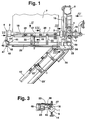
- 1 to 4 is a device for dripping Melting is shown after in practice under the name "Rotoform" known method works.
- This device exists from two concentric drums, from which the outer (1) in a manner not shown on their entire circumference and almost the full length with openings is provided.
- This outer tubular drum (1) has both ends bearing (2), with which they are on the inner cylindrical Drum is rotatably mounted.
- the inner drum is on its right end between two vertical plates (3) of a support frame (4) largely overhung and can Via connections (5) known per se with one to be dripped Melt and be supplied with a heating medium that for a Temperature control of the device ensures.
- a ring (6) is provided at the free, from the bearing plates (3) opposite end of the invisible inner drum body (see also Fig.
- a Drive motor (8) provided, the drive shaft (9) via a chain (10) a gear wheel which is firmly connected to the drum (1) (11) drives.
- the support frame (4) is not one on the support frame (12) attached cooling belt attached, in which also one from Fig. 4 apparent deflection drum (13) is arranged over the the conveyor or cooling belt (7) is guided.
- a support device is placed from below (14), which in the exemplary embodiment is a micrometer screw is trained.
- the inner drum is adjustable to a certain extent arranged between the two plates (3). Such an adjustment is e.g. then required if from manufacturing one product is to be transferred to another and if for this purpose the drain point for the melt opposite the transport and cooling belt (7) changed slightly, for example compared to one running through the drum axis Vertical plane slightly in front of or in the direction opposite to the tape running direction Belt direction should be readjusted. This will do so achieved that the inner drum body then fixed during operation (16) in the area between the two bearing plates (3), i.e. in the area between its two bearings (17) with a Worm wheel (18) is provided, which is fixedly connected to it and one that is only hinted at in the figures The worm spindle (19) can be adjusted using a handwheel (20).
- the worm gear is designed so that it is self-locking works. Therefore, are those set for the once Location of the inner drum body (16) provided locking devices solved, even then an unwanted twist of the inner drum body (16) do not occur when from the drive (8) is switched on for any reason.
- the Self-locking of the worm gear keeps the inner drum body (16) firmly in place. The danger that when solved Storage of the inner drum (16) therefore this with the Twisted connections (5) and hose connections, not shown, therefore does not exist.
- the Length corresponds approximately to the drip width.
- This guide which is heated serves to adhere to the outer drum (1)
- Product residues that could interfere with the draining process press the draining point back into the openings.
- the guide (15) but also the peripheral surface of the drum (1), e.g. must be made accessible for maintenance purposes the guide (15) via support arms (22) with a swivel arm (23) connected to the support frame (4) by a perpendicular to the Axis (21) of the drums (1 and 16) pivot axis (24) from the circumference of the drum (1) pivotable and for example in the position (23 ') is movable.
- the pivot axis (24) and the mounting of the swivel arm (23) is a quarter circle Locking device (25) with three locking recesses assigned to the with a not shown notch on the swivel arm (23) interact and this for example in the position (23 ') can lock.
- the swivel arm (23) is also a Damping cylinder (26) in connection, on the fixed locking disc (24) is articulated. This damping cylinder (26) is off Security reasons provided to prevent, for example then when the locking of the swivel arm (23) unintentionally disengages, the swivel arm, which is folded upwards, falls too quickly and, for example, the one performing maintenance Harming person.
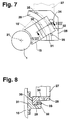
- a holder (27) is connected to the holding arms (22) which, as can be seen from FIGS. 7 and 8, two guide plates (28) are attached, each with a web (29) in the Are provided in the form of a quarter-circle arc.
- This quarter-circle arc (29) has a center that is on the axis (21) of the drums (1, 16).
- the instructor sits with a bracket (31) which is one of the Inner curvature of the web (29) adapted guide part (30) and a guide edge (32) overlapping the web (29) in a U-shape has, in which a clamping screw (33) is arranged.
- the Guide (15) can therefore be in on the quarter circle web (29) adjust to a certain extent relative to the drum (1) without the swivel arm (23) would have to be adjusted for this purpose.
- the guide plates (28) are over in the embodiment Bolt (34) connected to the bracket (27).
- the quarter circle bridge (29) are assigned two stops (35), so that in very simple adjustment of the guide (15) by 7 shown in dashed lines in FIG second layer (15 ') is possible.
- the ring (6) is fixed with a laterally projecting cone (38) provided with a screw pin at its free end (39) is provided.
- a laterally projecting cone (38) provided with a screw pin at its free end (39) is provided.
- One in a cylindrical part in front of the The cone (38) inserted stud screw (40) is used to prevent rotation in a slot (41) of a sleeve (42), the one has the inner recess (43) adapted to the cone (38).
- the Sleeve (42) is fixedly connected to a support plate (44) again via an intermediate piece (45) and a right-angled one its extending flange (46) is connected to the swivel arm (23) is.
- a sleeve (47) is rotatably mounted in the support plate (44), the one at its free end with a knurled handwheel (48) is provided.
- the sleeve (47) has one in one of the conical Recess (43) upstream recess of the sleeve (42) protruding head in which a threaded bore (50) is arranged whose thread corresponds to the thread of the screw pin (39).
- the connection between the swivel arm (23) and the Free end (16a) of the drum (16) is therefore over the ring and reached the cone (38) and via the sleeve (42).
- the through the cone (38) is given a precise fit by the screw sleeve (49) secured.
- the swivel arm (23) can be attached to the Guide (15) swung down and, for example, in the position (23 ') (see Fig. 1) can be locked. Thanks to the new design is a perfect orientation of the guide to Drum (1) possible without difficulty for a desired Swiveling process exist.
Landscapes
- Chemical & Material Sciences (AREA)
- Engineering & Computer Science (AREA)
- Mechanical Engineering (AREA)
- Organic Chemistry (AREA)
- Chemical Kinetics & Catalysis (AREA)
- Thermal Sciences (AREA)
- Physics & Mathematics (AREA)
- Auxiliary Devices For And Details Of Packaging Control (AREA)
- Processing And Handling Of Plastics And Other Materials For Molding In General (AREA)
- Tyre Moulding (AREA)
- Glanulating (AREA)
- Harvesting Machines For Root Crops (AREA)
- Rolls And Other Rotary Bodies (AREA)
- Discharge By Other Means (AREA)
- Structure Of Belt Conveyors (AREA)
- Control Of Conveyors (AREA)
- Separation, Sorting, Adjustment, Or Bending Of Sheets To Be Conveyed (AREA)
- Extrusion Moulding Of Plastics Or The Like (AREA)
- Treatment Of Fiber Materials (AREA)
Claims (10)
- Dispositif permettant d'évacuer sous forme de bandes ou de gouttes des masses coulantes sur une bande transporteuse (7) guidée et passant au-dessous avec deux tambours (16, 1) rotatifs l'un par rapport à l'autre qui sont logés de façon concentrique l'un dans l'autre, le tambour (1) extérieur rotatif étant pourvu d'ouvertures, qui peuvent être amenées par rotation pour coïncider de façon cyclique avec au moins une ouverture, tournée vers la bande transporteuse (7) et correspondant à la largeur de la bande transporteuse, du tambour (16) intérieur fixe, et avec un guide (15) entourant le tambour (1) extérieur dans une zone périphérique opposée à la bande transporteuse (7), lequel guide est disposé de façon à pouvoir basculer autour d'un axe (24) disposé dans un support basculant (25) en s'éloignant de l'enveloppe du tambour (1) et est bloqué dans la position de service parallèlement à l'axe du tambour (21) par un dispositif de retenue s'appliquant de façon coaxiale sur le tambour fixe, caractérisé en ce que le tambour intérieur (16) est un peu plus long que le tambour (1) extérieur pivotant et dépasse du tambour pivotant à l'extrémité libre (16a), et en ce que le dispositif de retenue comprend une bague (6) guidée de façon pivotante sur cette extrémité libre (16a) du tambour (16) fixe et un système de couplage (38, 42) fixé de façon radiale et amovible sur la bague, lequel système est disposé sur l'extrémité du guide opposée à l'axe de pivotement (24).
- Dispositif selon la revendication 1, caractérisé en ce que la bague (6) est guidée sur une surface de guidage du tambour (16) fixe de façon qu'il existe une certaine possibilité de déplacement axial.
- Dispositif selon les revendications 1 et 2, caractérisé en ce que la bague (6) est pourvue sur son diamètre intérieur de bagues (37) appliquées de façon élastique sur le tambour fixe (16, 16a).
- Dispositif selon la revendication 1, caractérisé en ce que le système de couplage comprend un cône (38) attribué à l'une des deux parties à accoupler et une douille de logement (42) attribuée à l'autre partie pour le cône.
- Dispositif selon la revendication 4, caractérisé en ce que le cône (38) et la douille de logement (42) sont bloqués l'un dans l'autre par un tenon à vis (39) se déplaçant dans le sens axial.
- Dispositif selon la revendication 5, caractérisé en ce que le tenon à vis (39) est relié à un écrou moleté (49, 48) logé de façon pivotante sur la fixation (23) pour le guide (15).
- Dispositif selon la revendication 1, caractérisé en ce qu'il est prévu pour le guide (15) un bras de retenue (17), qui est relié au bras pivotant (23), et en ce que ce bras de retenue (27) est pourvu de plaques de guidage (28) pour le guide (15), qui sont pourvues d'un guide à coulisse (29) pour les parties coulissantes (30, 32) reliées au guide, le guide à coulisse correspondant à une partie d'un arc de cercle, dont le centre se situe sur l'axe du tambour (21).
- Dispositif selon la revendication 7, caractérisé en ce que le guide à coulisse est conçu comme une barrette (29) décrivant un quart de circonférence, sur laquelle est guidée une pièce coulissante (30) reliée au guide, à laquelle est attribuée une pièce de blocage (32) entourant au moins partiellement la barrette (29).
- Dispositif selon la revendication 1 avec un tambour (16) fixe, réglable en angle autour de son axe (21) et retenu dans un cadre porteur (4) stationnaire, caractérisé en ce que le réglage d'angle du tambour (16) fixe s'effectue à l'aide d'un engrenage autobloquant à vis sans fin (18, 19), dont la roue (18) et la broche (19) sont attribuées respectivement au tambour (16) et au cadre porteur fixe (4).
- Dispositif selon la revendication 9, caractérisé en ce que la broche à vis sans fin est pourvue d'un boulon (20).
Applications Claiming Priority (3)
| Application Number | Priority Date | Filing Date | Title |
|---|---|---|---|
| DE4419491A DE4419491C1 (de) | 1994-06-03 | 1994-06-03 | Vorrichtung zum streifen- oder tropfenförmigen Ausbringen fließfähiger Massen auf ein Transportband |
| DE4419491 | 1994-06-03 | ||
| PCT/EP1995/001964 WO1995033551A1 (fr) | 1994-06-03 | 1995-05-23 | Dispositif permettant de charger sous forme de bandes ou de gouttes des materiaux coulants sur une bande transporteuse |
Publications (2)
| Publication Number | Publication Date |
|---|---|
| EP0712331A1 EP0712331A1 (fr) | 1996-05-22 |
| EP0712331B1 true EP0712331B1 (fr) | 1998-11-18 |
Family
ID=6519749
Family Applications (1)
| Application Number | Title | Priority Date | Filing Date |
|---|---|---|---|
| EP95922477A Expired - Lifetime EP0712331B1 (fr) | 1994-06-03 | 1995-05-23 | Dispositif permettant de charger sous forme de bandes ou de gouttes des materiaux coulants sur une bande transporteuse |
Country Status (11)
| Country | Link |
|---|---|
| US (1) | US5730329A (fr) |
| EP (1) | EP0712331B1 (fr) |
| JP (1) | JP2909843B2 (fr) |
| KR (1) | KR960703663A (fr) |
| CN (1) | CN1129406A (fr) |
| AT (1) | ATE173415T1 (fr) |
| AU (1) | AU681039B2 (fr) |
| CA (1) | CA2168468A1 (fr) |
| DE (2) | DE4419491C1 (fr) |
| RU (1) | RU2109558C1 (fr) |
| WO (1) | WO1995033551A1 (fr) |
Families Citing this family (3)
| Publication number | Priority date | Publication date | Assignee | Title |
|---|---|---|---|---|
| DE10306688B3 (de) * | 2003-02-11 | 2004-11-11 | Santrade Ltd. | Vorrichtung zur Herstellung von Granulat |
| RU2412753C1 (ru) * | 2009-09-25 | 2011-02-27 | Государственное образовательное учреждение высшего профессионального образования "Белгородский государственный технологический университет им. В.Г. Шухова" (БГТУ им. В.Г. Шухова) | Вибрационно-центробежный гранулятор |
| DE102024114210A1 (de) * | 2024-05-22 | 2025-11-27 | Ipco Germany Gmbh | Tropfenformer und Vorrichtung mit einem Tropfenformer |
Family Cites Families (6)
| Publication number | Priority date | Publication date | Assignee | Title |
|---|---|---|---|---|
| EP0012192B1 (fr) * | 1978-12-08 | 1983-01-12 | Santrade Ltd. | Dispositif pour extruder des masses fluides d'un récipient |
| US4578021A (en) * | 1983-11-01 | 1986-03-25 | Santrade Ltd. | Apparatus for the production of granules from two-phase mixtures |
| DE3813756C1 (fr) * | 1988-04-23 | 1989-03-02 | Santrade Ltd., Luzern, Ch | |
| DE4032683C3 (de) * | 1990-10-15 | 1996-06-13 | Santrade Ltd | Vorrichtung zur Bildung von Tropfen |
| DE4119021C1 (fr) * | 1991-06-09 | 1992-08-13 | Santrade Ltd., Luzern, Ch | |
| DE4244035C1 (de) * | 1992-12-24 | 1994-02-03 | Santrade Ltd | Vorrichtung zur Herstellung von Granulat |
-
1994
- 1994-06-03 DE DE4419491A patent/DE4419491C1/de not_active Expired - Fee Related
-
1995
- 1995-05-23 CA CA002168468A patent/CA2168468A1/fr not_active Abandoned
- 1995-05-23 KR KR1019960700509A patent/KR960703663A/ko not_active Ceased
- 1995-05-23 US US08/596,180 patent/US5730329A/en not_active Expired - Lifetime
- 1995-05-23 WO PCT/EP1995/001964 patent/WO1995033551A1/fr not_active Ceased
- 1995-05-23 AT AT95922477T patent/ATE173415T1/de not_active IP Right Cessation
- 1995-05-23 CN CN95190517A patent/CN1129406A/zh active Pending
- 1995-05-23 AU AU27361/95A patent/AU681039B2/en not_active Ceased
- 1995-05-23 DE DE59504257T patent/DE59504257D1/de not_active Expired - Lifetime
- 1995-05-23 EP EP95922477A patent/EP0712331B1/fr not_active Expired - Lifetime
- 1995-05-23 JP JP8500269A patent/JP2909843B2/ja not_active Expired - Lifetime
- 1995-12-14 RU RU96104256A patent/RU2109558C1/ru active
Also Published As
| Publication number | Publication date |
|---|---|
| US5730329A (en) | 1998-03-24 |
| JPH09501102A (ja) | 1997-02-04 |
| RU2109558C1 (ru) | 1998-04-27 |
| KR960703663A (ko) | 1996-08-31 |
| DE4419491C1 (de) | 1995-05-11 |
| EP0712331A1 (fr) | 1996-05-22 |
| CN1129406A (zh) | 1996-08-21 |
| DE59504257D1 (de) | 1998-12-24 |
| CA2168468A1 (fr) | 1995-12-14 |
| JP2909843B2 (ja) | 1999-06-23 |
| ATE173415T1 (de) | 1998-12-15 |
| WO1995033551A1 (fr) | 1995-12-14 |
| AU2736195A (en) | 1996-01-04 |
| AU681039B2 (en) | 1997-08-14 |
Similar Documents
| Publication | Publication Date | Title |
|---|---|---|
| EP0726216B1 (fr) | Roue de transport en forme d'étoile pour récipients | |
| EP0629171A1 (fr) | Element de raclage a monter sur un support de systeme d'un dispositif de raclage | |
| DE69807346T2 (de) | Halteranordnung für automobilkarosserieteile | |
| DE3541638A1 (de) | Werkstueckhaltevorrichtung | |
| DE19603627C2 (de) | Wirbelstrommühle | |
| DE19536692A1 (de) | Transportstern für Gefäße | |
| EP0712331B1 (fr) | Dispositif permettant de charger sous forme de bandes ou de gouttes des materiaux coulants sur une bande transporteuse | |
| DE2500958B2 (de) | Fraeswerkzeug zur aufbereitung des pfannenlagers bei totalprothetischem hueftgelenkersatz | |
| EP0017877B1 (fr) | Dispositif d'avance à roues planétaires pour fils à souder par fusion | |
| DE4306802C1 (de) | Deckenstativ | |
| EP0523369B1 (fr) | Dispositif pour changer les moyens de coupe d'une cisaille pour voguer ou refendre un matériau en bande | |
| DE19617713A1 (de) | Halterung für Rundmesserpaar | |
| DE3151737C2 (fr) | ||
| DE4407958A1 (de) | Fadenbremsvorrichtung | |
| DE2529702B2 (de) | Vorrichtung zum Befestigen des Wischerarmes auf dem Ende einer Wischlagerwelle | |
| EP0694344B1 (fr) | Tête nettoyeuse rotative | |
| DE10306688B3 (de) | Vorrichtung zur Herstellung von Granulat | |
| EP1240949A2 (fr) | Dispositif de distribution de fluides, en particulier d'adhésifs fluides | |
| CH410503A (de) | Vorrichtung zum Ausstreuen körnigen oder pulvrigen Materials | |
| EP0603701B1 (fr) | Appareil pour mettre sous forme de rubans ou de gouttelettes des masses fluides | |
| DE10305248B3 (de) | Vorrichtung zur randscharfen Applikation eines flüssigen oder pastösen Beschichtungsmaterials auf einen Gegenstand | |
| DE69301678T2 (de) | Verschlussvorrichtung | |
| DE3128113C2 (de) | Verstellbare Bandübergabe zur Verwendung im untertägigen Grubenbetrieb, mit einer um 360 Grad um einen Mittelpunkt stufenlos drehbaren Schurre | |
| DE2847614A1 (de) | Dreh-schieberverschluss fuer giesspfannen o.ae. | |
| DE3822489C2 (fr) |
Legal Events
| Date | Code | Title | Description |
|---|---|---|---|
| PUAI | Public reference made under article 153(3) epc to a published international application that has entered the european phase |
Free format text: ORIGINAL CODE: 0009012 |
|
| 17P | Request for examination filed |
Effective date: 19951230 |
|
| AK | Designated contracting states |
Kind code of ref document: A1 Designated state(s): AT BE CH DE DK ES FR GB GR IE IT LI LU MC NL PT SE |
|
| GRAG | Despatch of communication of intention to grant |
Free format text: ORIGINAL CODE: EPIDOS AGRA |
|
| 17Q | First examination report despatched |
Effective date: 19980311 |
|
| GRAG | Despatch of communication of intention to grant |
Free format text: ORIGINAL CODE: EPIDOS AGRA |
|
| GRAH | Despatch of communication of intention to grant a patent |
Free format text: ORIGINAL CODE: EPIDOS IGRA |
|
| GRAH | Despatch of communication of intention to grant a patent |
Free format text: ORIGINAL CODE: EPIDOS IGRA |
|
| GRAA | (expected) grant |
Free format text: ORIGINAL CODE: 0009210 |
|
| AK | Designated contracting states |
Kind code of ref document: B1 Designated state(s): AT BE CH DE DK ES FR GB GR IE IT LI LU MC NL PT SE |
|
| PG25 | Lapsed in a contracting state [announced via postgrant information from national office to epo] |
Ref country code: SE Free format text: THE PATENT HAS BEEN ANNULLED BY A DECISION OF A NATIONAL AUTHORITY Effective date: 19981118 Ref country code: NL Free format text: LAPSE BECAUSE OF FAILURE TO SUBMIT A TRANSLATION OF THE DESCRIPTION OR TO PAY THE FEE WITHIN THE PRESCRIBED TIME-LIMIT Effective date: 19981118 Ref country code: GR Free format text: LAPSE BECAUSE OF NON-PAYMENT OF DUE FEES Effective date: 19981118 Ref country code: GB Free format text: LAPSE BECAUSE OF NON-PAYMENT OF DUE FEES Effective date: 19981118 Ref country code: FR Free format text: LAPSE BECAUSE OF FAILURE TO SUBMIT A TRANSLATION OF THE DESCRIPTION OR TO PAY THE FEE WITHIN THE PRESCRIBED TIME-LIMIT Effective date: 19981118 Ref country code: ES Free format text: THE PATENT HAS BEEN ANNULLED BY A DECISION OF A NATIONAL AUTHORITY Effective date: 19981118 |
|
| REF | Corresponds to: |
Ref document number: 173415 Country of ref document: AT Date of ref document: 19981215 Kind code of ref document: T |
|
| REG | Reference to a national code |
Ref country code: CH Ref legal event code: EP |
|
| REF | Corresponds to: |
Ref document number: 59504257 Country of ref document: DE Date of ref document: 19981224 |
|
| REG | Reference to a national code |
Ref country code: IE Ref legal event code: FG4D Free format text: GERMAN |
|
| ITF | It: translation for a ep patent filed | ||
| PG25 | Lapsed in a contracting state [announced via postgrant information from national office to epo] |
Ref country code: PT Free format text: LAPSE BECAUSE OF FAILURE TO SUBMIT A TRANSLATION OF THE DESCRIPTION OR TO PAY THE FEE WITHIN THE PRESCRIBED TIME-LIMIT Effective date: 19990218 Ref country code: DK Free format text: LAPSE BECAUSE OF FAILURE TO SUBMIT A TRANSLATION OF THE DESCRIPTION OR TO PAY THE FEE WITHIN THE PRESCRIBED TIME-LIMIT Effective date: 19990218 |
|
| EN | Fr: translation not filed | ||
| NLV1 | Nl: lapsed or annulled due to failure to fulfill the requirements of art. 29p and 29m of the patents act | ||
| PGFP | Annual fee paid to national office [announced via postgrant information from national office to epo] |
Ref country code: AT Payment date: 19990512 Year of fee payment: 5 |
|
| GBV | Gb: ep patent (uk) treated as always having been void in accordance with gb section 77(7)/1977 [no translation filed] |
Effective date: 19981118 |
|
| PG25 | Lapsed in a contracting state [announced via postgrant information from national office to epo] |
Ref country code: LU Free format text: LAPSE BECAUSE OF NON-PAYMENT OF DUE FEES Effective date: 19990523 |
|
| PG25 | Lapsed in a contracting state [announced via postgrant information from national office to epo] |
Ref country code: LI Free format text: LAPSE BECAUSE OF NON-PAYMENT OF DUE FEES Effective date: 19990531 Ref country code: CH Free format text: LAPSE BECAUSE OF NON-PAYMENT OF DUE FEES Effective date: 19990531 Ref country code: BE Free format text: LAPSE BECAUSE OF NON-PAYMENT OF DUE FEES Effective date: 19990531 |
|
| PG25 | Lapsed in a contracting state [announced via postgrant information from national office to epo] |
Ref country code: IE Free format text: LAPSE BECAUSE OF NON-PAYMENT OF DUE FEES Effective date: 19990820 |
|
| PLBE | No opposition filed within time limit |
Free format text: ORIGINAL CODE: 0009261 |
|
| STAA | Information on the status of an ep patent application or granted ep patent |
Free format text: STATUS: NO OPPOSITION FILED WITHIN TIME LIMIT |
|
| REG | Reference to a national code |
Ref country code: IE Ref legal event code: FD4D |
|
| 26N | No opposition filed | ||
| BERE | Be: lapsed |
Owner name: SANTRADE LTD Effective date: 19990531 |
|
| PG25 | Lapsed in a contracting state [announced via postgrant information from national office to epo] |
Ref country code: MC Free format text: LAPSE BECAUSE OF NON-PAYMENT OF DUE FEES Effective date: 19991130 |
|
| REG | Reference to a national code |
Ref country code: CH Ref legal event code: PL |
|
| PG25 | Lapsed in a contracting state [announced via postgrant information from national office to epo] |
Ref country code: AT Free format text: LAPSE BECAUSE OF NON-PAYMENT OF DUE FEES Effective date: 20000523 |
|
| PG25 | Lapsed in a contracting state [announced via postgrant information from national office to epo] |
Ref country code: IT Free format text: LAPSE BECAUSE OF NON-PAYMENT OF DUE FEES Effective date: 20050523 |
|
| PGFP | Annual fee paid to national office [announced via postgrant information from national office to epo] |
Ref country code: DE Payment date: 20140521 Year of fee payment: 20 |
|
| REG | Reference to a national code |
Ref country code: DE Ref legal event code: R071 Ref document number: 59504257 Country of ref document: DE |