EP0018257A1 - Vorrichtung zur Anlass-Vorwärmung eines Verbrennungsmotors des Dieseltyps oder dgl. - Google Patents
Vorrichtung zur Anlass-Vorwärmung eines Verbrennungsmotors des Dieseltyps oder dgl. Download PDFInfo
- Publication number
- EP0018257A1 EP0018257A1 EP80400436A EP80400436A EP0018257A1 EP 0018257 A1 EP0018257 A1 EP 0018257A1 EP 80400436 A EP80400436 A EP 80400436A EP 80400436 A EP80400436 A EP 80400436A EP 0018257 A1 EP0018257 A1 EP 0018257A1
- Authority
- EP
- European Patent Office
- Prior art keywords
- output
- preheating
- input
- gate
- state
- Prior art date
- Legal status (The legal status is an assumption and is not a legal conclusion. Google has not performed a legal analysis and makes no representation as to the accuracy of the status listed.)
- Granted
Links
- 238000002485 combustion reaction Methods 0.000 title claims description 18
- 239000007858 starting material Substances 0.000 claims abstract description 72
- 230000009471 action Effects 0.000 claims abstract description 6
- 239000003990 capacitor Substances 0.000 claims description 20
- 230000001960 triggered effect Effects 0.000 claims description 18
- 230000004913 activation Effects 0.000 claims description 7
- 230000008859 change Effects 0.000 claims description 7
- 238000012423 maintenance Methods 0.000 claims description 5
- 230000001627 detrimental effect Effects 0.000 claims description 4
- 238000010586 diagram Methods 0.000 description 30
- 238000010438 heat treatment Methods 0.000 description 21
- 239000004020 conductor Substances 0.000 description 7
- 230000007704 transition Effects 0.000 description 6
- 238000004804 winding Methods 0.000 description 6
- 230000007935 neutral effect Effects 0.000 description 4
- 230000000630 rising effect Effects 0.000 description 3
- 239000000498 cooling water Substances 0.000 description 2
- 230000006378 damage Effects 0.000 description 2
- 238000007493 shaping process Methods 0.000 description 2
- 238000001816 cooling Methods 0.000 description 1
- 230000003247 decreasing effect Effects 0.000 description 1
- 230000001934 delay Effects 0.000 description 1
- 230000000779 depleting effect Effects 0.000 description 1
- 230000006866 deterioration Effects 0.000 description 1
- 230000035484 reaction time Effects 0.000 description 1
- 230000009467 reduction Effects 0.000 description 1
Images


Classifications
-
- F—MECHANICAL ENGINEERING; LIGHTING; HEATING; WEAPONS; BLASTING
- F02—COMBUSTION ENGINES; HOT-GAS OR COMBUSTION-PRODUCT ENGINE PLANTS
- F02P—IGNITION, OTHER THAN COMPRESSION IGNITION, FOR INTERNAL-COMBUSTION ENGINES; TESTING OF IGNITION TIMING IN COMPRESSION-IGNITION ENGINES
- F02P19/00—Incandescent ignition, e.g. during starting of internal combustion engines; Combination of incandescent and spark ignition
- F02P19/02—Incandescent ignition, e.g. during starting of internal combustion engines; Combination of incandescent and spark ignition electric, e.g. layout of circuits of apparatus having glowing plugs
-
- F—MECHANICAL ENGINEERING; LIGHTING; HEATING; WEAPONS; BLASTING
- F02—COMBUSTION ENGINES; HOT-GAS OR COMBUSTION-PRODUCT ENGINE PLANTS
- F02B—INTERNAL-COMBUSTION PISTON ENGINES; COMBUSTION ENGINES IN GENERAL
- F02B1/00—Engines characterised by fuel-air mixture compression
- F02B1/02—Engines characterised by fuel-air mixture compression with positive ignition
- F02B1/04—Engines characterised by fuel-air mixture compression with positive ignition with fuel-air mixture admission into cylinder
-
- F—MECHANICAL ENGINEERING; LIGHTING; HEATING; WEAPONS; BLASTING
- F02—COMBUSTION ENGINES; HOT-GAS OR COMBUSTION-PRODUCT ENGINE PLANTS
- F02B—INTERNAL-COMBUSTION PISTON ENGINES; COMBUSTION ENGINES IN GENERAL
- F02B3/00—Engines characterised by air compression and subsequent fuel addition
- F02B3/06—Engines characterised by air compression and subsequent fuel addition with compression ignition
Definitions
- the invention relates to a preheating device for starting an internal combustion engine, of the Diesel type or the like, comprising a glow plug, mounted in each cylinder, suitable for being supplied by a source of electrical energy for ensuring the preheating of a combustion chamber, comprising a rapid preheating circuit ensuring the connection of each glow plug under a relatively high electrical voltage, this rapid preheating circuit being normally put into action from the start of preheating, and one. slow preheating circuit suitable for ensuring the connection of each glow plug at a lower electrical voltage after a rapid preheating period determined by first delay means.
- starting engines of the Diesel type or the like requires such preheating, especially when the engine is cold. This is a disadvantage compared to internal combustion engines; in fact, after turning the ignition key, the driver must generally wait for the appearance of a signal, in particular a light signal (indicating that preheating is sufficient) before actuating the starter with a view to starting the engine.
- a signal in particular a light signal (indicating that preheating is sufficient)
- the object of the invention is, above all, to make this preheating device such that it better meets the various requirements of practice than hitherto, and in particular such that it makes it possible to start a motor vehicle from Diesel or similar type, provided with the preheating device of the invention, practically as easy as starting a vehicle equipped with a petrol engine.
- a preheating device for starting an internal combustion engine in particular a diesel engine of the kind defined above, is characterized by the fact that the above first time delay means are combined: with means sensitive to the temperature of the engine, arranged in such a way that the rapid preheating time depends on the temperature of the engine and that control means are designed to automatically close the starter supply circuit when the fast preheating circuit is cut off and / or to close the slow preheating circuit.
- Means sensitive to the engine speed are provided to control the engine shutdown and slow preheating when the internal combustion engine is running at sufficient speed.
- the device comprises means sensitive to a previous start order combined with control means so as to prohibit or stop the actuation of the rapid preheating circuit during a determined time interval following a start attempt or the engine shutdown.
- the rapid preheating circuit ensures the connection of the glow plugs under a temporary electrical overvoltage such that the temperature rise of the plugs is rapid.
- the first delay means are, advantageously, electronic, and comprise, for example, a CTN resistor (with a negative temperature coefficient) sensitive to the temperature of the motor; this resistance plunges, in particular, in the engine cooling water.
- the means sensitive to an attempt to start advantageously comprise second time delay means.
- these second timing means are triggered when, after closing then opening of the starter contact, there is opening of the general contact, said second timing means then delivering a signal prohibiting the actuation of the preheating circuit, having a predetermined duration, while allowing slow preheating and launching of the starter.
- Means are provided to prevent the triggering of the second time delay means if there has been closing and then opening of the general contact, without the starter contact having been closed then opened.
- the output of the first timing means is connected, on the one hand, to an input of an AND gate, the output of which controls, possibly by means of an amplifier and a relay, the activation of the rapid preheating and, on the other hand, at the input of an inverting gate whose output is connected to the input of an OR gate;
- the output of this OR gate is connected to an input of a second AND gate, the output of which controls, in particular by means of an amplifier and a relay, the activation of slow preheating and of the starter;
- the output of the second timing means is connected to another input of the OR gate, and, via an inverting gate, to another input of the first AND gate; a second input of the second AND gate is attacked by a signal produced when the starter contact closes.
- the first and second AND doors have a third input connected to an engine speed detector, arranged so as to provide a preheating prohibition signal when the engine is running at a sufficient speed.
- These means are suitable for storing the fugitive closing of the starter contact, in order to maintain, on the input of the second AND gate, normally attacked by the closing signal of the starter contact, a command to start preheating. slow and starting.
- These storage means are advantageously formed by a flip-flop D whose clock input is connected so as to be attacked by the fugitive signal for closing the starter contact, while the input D (data) of this flip-flop is connected to the output of a third AND gate having two inputs driven respectively by the signal at the output of the engine speed detector and by a signal appearing when the general contact is closed; the output of flip-flop D is connected to an input of the second AND gate.
- the means sensitive to a previous start order comprise means sensitive to the temperature of the glow plug combined with second timing means, the assembly being arranged in such a way that rapid preheating is stopped if the temperature of the spark plug has reached or exceeds a values o during a time interval, which follows the closing of the starter contact, less than the duration of switching of the second timing means, the slow preheating and the launching of the starter being then controlled.
- the means sensitive to the temperature of the spark plug are advantageously constituted by a detector of intensity which makes it possible to deduce, from the intensity which passes through the candle supplied by a known electric voltage source, the temperature of this candle.
- the output of the intensity detector is connected, via a flip-flop RS, to an input of a "NAND” gate, another input of which is connected to the output of the second delay means; the output of this "NAND” gate is connected to the input of a flip-flop, an output of which is connected to an input for resetting the first delay means to zero.
- the first delay means are started by closing, even fleeting, the starter contact so that rapid preheating begins with this closing.
- the intensity detector gives information showing that the candle was already hot
- the first delay means are reset and rapid preheating is stopped.
- These first delay means are adjusted so as to have a maximum switching time such that if a glow plug having a temperature equal to 0, is subjected, during this maximum switching time, to the relatively high electrical voltage (rapid preheating) , it is certain that at the end of this maximum switching time, the temperature reached by the glow plug is not detrimental to this plug.
- the assembly is arranged in such a way that, in the case of a cold candle, the first delay means and the rapid preheating are triggered when the starter contact is closed and that, when the glow plug reaches the temperature 0 00 the first time delay means are retriggered so that the glow plug is subjected to rapid preheating during a time interval maximum ⁇ t1 + ⁇ tm determined by the time delay from time to.
- the intensity detector is arranged to control, when crossing a corresponding value i o at the temperature ⁇ 0 , by the intensity absorbed, a change of state of the output of the associated flip-flop, this change of state controlling the re-triggering of the first time delay means.
- circuit for bypassing the first delay means comprising, in particular an AND gate.
- Means are also provided for controlling the stopping of rapid preheating and the transition to slow preheating with starting, if the engine is sufficiently hot.
- These means include third time-delay means, capable of delivering a tilting slot of fixed duration, and means for reading the charge of a capacitor through a CTN resistor sensitive to the temperature of the motor; if the voltage across the capacitor reaches a determined value in a time less than the switching time of the third delay means (which translates to a low value of the CTN resistance and therefore a relatively high temperature of the motor), rapid preheating is stopped and the start of the slow preheating and the starter is controlled.
- the means for reading the charge of the capacitor comprise a comparator capable of comparing the voltage across the terminals of the capacitor with a reference voltage, the output of this comparator being connected to an input of a "NAND" gate, the other input of which is connected to the output of the third time delay means.
- the duration of the tilting slot of these third time delay means can be of the order of 0.5 seconds.
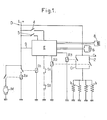
- Figure 1 of these drawings is a diagram of a preheating device according to the invention, according to the first solution mentioned above.
- Figure 2 is a block diagram of the electronic assembly of a device according to FIG. 1, in the case of an assisted start, i.e. say with the driver keeping the starter contact closed.
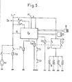
- Figure 3 is a block diagram of the electronic assembly in the case of a fully automatic start, that is to say with fugitive closing of the starter contact and release of the ignition key.
- Figure 4 is a diagram summarizing the operation of the starting device according to the first solution.
- FIG. 5 is an overall diagram of a preheating device, according to the invention, in accordance with the second solution mentioned above.
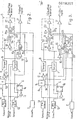
- FIG. 6 is a block diagram of the electronic assembly of the device of FIG. 5.
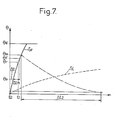
- FIG. 7 gives representative schematic curves of the heating of a candle, the temperature 0 of which is plotted on the ordinate, as a function of the time t plotted on the abscissa, for rapid preheating and for slow preheating.
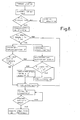
- FIG. 8 is a diagram summarizing the operation of the device of FIGS. 5 and 6.
- FIG. 9 is a diagram representing the logic states at different points of the electronic circuit of the diagram in FIG. 6.
- FIG. 10 is a diagram of an additional electronic circuit enabling post-heating to be maintained after starting.
- FIG. 11 is a diagram of an electronic circuit enabling the glow plugs to be supplied under reduced power, for slow preheating or post-heating.
- FIG. 12 is a variant of the diagram in FIG. 11.
- FIG. 13 is a diagram of a circuit capable of limiting the supply time of the starter to a determined value.
- FIG. 14, finally, is a diagram of a circuit capable of authorizing the launching of the starter only if safety measures are respected.
- This preheating device comprises, mounted in each cylinder, a glow plug b shown diagrammatically in the form of an electrical resistance.
- a glow plug b shown diagrammatically in the form of an electrical resistance.
- four candles b have been represented; each spark plug ensures the preheating of a combustion chamber associated with the cylinder.
- the candles b are suitable for being powered by an electrical energy source whose pole + is connected to the conductor 1 and the pole - is connected to ground.
- This energy source is generally constituted by the battery of a vehicle equipped with the internal combustion engine.
- the device D comprises an electronic control unit E in which are provided first timing means 1 (fig. 2 and 3).
- the device D comprises a rapid preheating circuit Cr ensuring the connection of each glow plug b under a relatively high electrical voltage.
- the closing of this circuit Cr is controlled by a working contact of an electromagnetic relay R3 whose control coil is connected between earth and an output of the control assembly E; alternatively, the coil could be connected between the + pole and the assembly E.
- the preheating circuit Cr ensures the direct connection of the glow plugs b in parallel between the terminals of the electric power source and earth.
- the voltage thus applied to the spark plugs b is greater than the nominal operating voltage candles b; this voltage is such that if the candles b were kept for a relatively long time, they would be brought to a temperature too high for them to be able to resist.
- this voltage is of the order of 12 volts, while the spark plugs b have a nominal voltage of the order of 7 volts.
- the device D also includes a slow preheating circuit C1 which can be closed by the working contact of an electromagnetic control relay R2, the control winding of which is connected between ground and an output of the assembly E; according to a variant, this winding could be connected between the pole + and E.
- This circuit C1 comprises a falling resistor 2 (fig. 1). The closing of the circuit C1 ensures the supply in parallel of the spark plugs b, through this resistor 2; the voltage applied to the candles is therefore lower.
- the curve S1 in FIG. 7, which has a markedly lower slope than Sr, corresponds to the heating of the spark plug when only the circuit Cl is in action.
- the curve Sr (fig. 7) is given as steep a slope as possible.
- the first time delay means 1 are arranged to cut off the rapid preheating circuit Cr after a time tl (fig. 7) determined so that the spark plugs are not likely to be detected improved, that is to say in such a way that the temperature of the candles is limited to a value 0r less than the destruction temperature Or less than the destruction temperature 0d of the candle.
- the device D also comprises control means 3 (fig. 2) provided to ensure, when the rapid heating circuit Cr is opened, the slow heating circuit CI is closed (closing of the working contact of the relay R2 in FIG. 1) and the closing of the starter M supply circuit.
- control means 3 (fig. 2) provided to ensure, when the rapid heating circuit Cr is opened, the slow heating circuit CI is closed (closing of the working contact of the relay R2 in FIG. 1) and the closing of the starter M supply circuit.
- This closing of the starter circuit M is ensured by means of a work contact of a power relay Rd (fig. 1), the control winding of which is supplied via a work contact of a relay R1.
- the winding of R1 is connected between earth and an output of the control assembly E; alternatively, this winding could be connected between the + pole and E.
- an input of the control assembly E is connected to the conductor 1, connected to the + terminal of the battery, by a switch 4 suitable for being closed when the vehicle ignition key is placed in the general contact closing position.
- Another input of the assembly E is connected to the conductor 1 by means of a switch 5 suitable for being closed when the vehicle ignition key is placed in the "start" position.
- Two inputs of the assembly E are connected to the terminals of a resistor CTN (negative temperature coefficient) 6 sensitive to the temperature of the motor. This resistor 6 can, in particular, be immersed in the engine cooling water circuit.
- the two inputs of the assembly E connected to this resistor 6 are connected to two inputs of the timing means 1 as visible in FIG. 2.
- Two other inputs of assembly E (connected as visible in FIG. 2 to a detector 7 of engine speed) are connected to the terminals of a tachometer sensor 8 sensitive to the engine speed.
- control unit E Another input of the control unit E is permanently connected by a conductor 9 (fig. 1) to the conductor 1.
- the device D comprises means B (fig. 2), sensitive to an attempt to start, combined with control means 10 (fig. 2) so as to prohibit or stop the actuation of the rapid preheating circuit Cr during a time interval ⁇ t following a first start-up attempt.
- the sensitive means B ′ comprise second timing means 11.
- Means G are provided to prevent the triggering of the second delay means 11 if there has been closing then opening of the single general contact 4, without the starter contact 5 having been closed then opened.
- These second timing means 11 are suitable for delivering, when they have been triggered, a signal prohibiting the actuation of the rapid preheating circuit, while allowing slow preheating and the launching of the starter.
- the trigger input of the first delay means 1 is connected to the output of an anti-rebound circuit or shaping circuit 12.
- the input of this circuit 12 is connected so as to receive a logic signal "1" when closing the starter contact 5.
- the trigger input of the second timing means 11 is connected to the output of an inverter 13.
- the input of this inverter 13 is connected to the output of a flip-flop D, designated by the reference gl, belonging to the means G .
- the data gll input of this flip-flop is connected to the output of an anti-rebound circuit 14 or of shaping; the input of this circuit 14 is attacked by a trigger signal when the general contact 4 is cut.
- the clock input g12 of the flip-flop gl is linked to a complemented reset input g13; the passage from state "1" to state "0" of this input g13 therefore resets the output of the flip-flop to zero.
- the clock input g12 is also connected to the output Q of an R / S flip-flop g2 also belonging to the means G.
- the input S of the flip-flop g2 is connected to the output of the anti-rebound circuit 12.
- L the input R of the flip-flop g2 is connected to the output of an inverting gate g3 the input of which is connected to the output of the anti-rebound circuit 14.
- the control means 10 comprise an AND gate 15, an input 15e of which is connected to the output of the timing means 1; a second input 15f of this AND gate is connected to the output of an inverter 16 whose input is connected to the output of the timing means 11.
- a third door input 15g is connected to the output of the speed detector 7.
- the output of the speed detector 7 is in logic state "1" when the engine is stopped or is running at a speed lower than a determined limit (or threshold).
- the delay means 1 and 11 when triggered, show, at their output, for a determined time, the logic state "1".
- gate ET 15 command, by by means of an amplifier 17, the energization of the relay R3 for controlling the rapid heating circuit Cr and the closing of the work contact ensuring the supply of the spark plugs b by this rapid heating circuit.
- the control means 3 comprise an inverter circuit 18 whose input is connected to the output of the timing means 1 and whose output is connected to an input 19e of an OR gate 19. Another input 19f of this OR gate is connected to the output of the second timing means 11.
- the output of the OR gate 19 is connected to an input 20e of an AND gate 20; a second entrance 20f from this door. is connected to the output of the anti-rebound circuit 12. A third input 20g of the door 20 is connected to the output of the speed detector 7.
- the output of door 20 controls, via an amplifier 21, the relay R2 for actuation of the slow preheating circuit C1, as well as the relay R1 for actuation of the starter.
- this is a first start order when the period of stopping the internal combustion engine has been sufficient or when, in the event of a cut-off during preheating, the ignition has been switched off long enough for a long time so that the temperature of the glow plugs drops to a relatively low temperature, close to room temperature.
- the duration of the signal of timer 11 is chosen equal to or greater than the interval t2 (fig. 7) necessary for a glow plug b, starting from its maximum admissible temperature 0m (fig. 7) to cool up to a temperature close to ambient temperature, by cooling in a motor which does not run, the two circuits Cr and Cl being open.
- Closing with maintenance of the start contact 5 produces a. signal "1" at the output of circuit 12; the delay means 1 are triggered by the rising edge of this signal; these time delay means 1 deliver a signal "1" at their output, the duration of which depends on the value of the thermistor 6 and therefore on the temperature of the motor. The duration of the signal is lower the higher the engine temperature.
- the signal "1" arrives at the 15th entrance of door 15.
- the signal "0", present at the output of the timing means 11, is transformed, by the inverter 16, into signal " 1" present on the second input 15f of the door 15.
- the speed detector 7 gives at its output a signal "1", also present on the third input 15g of door 15.
- This AND gate gives, at its output, a signal "1" commanding the closing of the working contact of the relay R3 and the actuation of the rapid preheating circuit Cr.
- OR gate 19 The two inputs of OR gate 19 are attacked by a signal "0" so that the output of gate 19 and therefore the output of gate AND 20 are also in state "0", prohibiting the actuation of the slow heating circuit C1 and the launching of the starter.
- the output of the first means 1 returns to the state "0" so that the output of the door 15 also changes to the state "0" and controls the shutdown of the rapid heating circuit Cr .
- the temperature of the spark plug has substantially reached the value 0r on the curve Sr.
- the output of this gate changes to the state “1" as well as the 20th input of the door 20.
- the second input 20f of this door is also in state “1” because the contact 5 is kept closed; the third 20g input is also in state “1” since the engine has not started.
- the output of door 20 is in state “1” and commands the closing of relay R2 and relay R1, which causes the slow preheating circuit C1 to be put into action and the starter M to start.
- second start order implies that an attempt to start is made when the glow plugs are already hot; during this second start attempt, it is therefore necessary to prevent rapid preheating.
- the ignition key and control circuit system is arranged, in a conventional manner, such that after a failed start attempt, it is necessary, before being able to make a new attempt, to open the general contact 4, then to close it again.
- contact 4 was therefore cut off beforehand.
- the means G intervene to ensure that this interruption of the contact 4 does not trigger the second time delay means 11 unless it has taken place after closing and then opening of the starter contact 5.
- a flip-flop D passes, on its output, the state which is on its "data” input, when the clock input is in the state "1".
- the flip-flop serves to let pass a signal for triggering the second delay means 11, when the contact 4 is opened, only if there has been an attempt to start, that is to say if the contact 5 has been closed. then opened.
- the reversing gate g3 transmits to the input R of the flip-flop g2 a signal which changes the output Q from the state "1" to the state "0".
- the inputs g12 (clock) and gl3 of the flip-flop gl are brought to the state "0", and the output of the flip-flop gl is reset to "0".
- the reversing door 13 transforms the leading edge from the transition from "1" to "0” from the gl exit into the rising edge from "0" to "1” on the input of the second timing means 11 which are thus triggered .
- timer 1 is started, while second timer 11 is still started.
- the output of door 20 is therefore in state "1" and controls the slow preheating and the actuation of the starter.
- the control assembly E allows an automatic starting sequence so that it is not necessary to keep the starting contact 5 closed; it suffices to make a fleeting closure of this contact 5 and release the ignition key, to trigger the automatic start sequence.
- control assembly of FIG. 3 includes means 22 suitable for storing the fleeting closing of the starter contact 5 in order to maintain, on the input 20f of the AND gate, a corresponding state "1" (when the other two inputs 20e and 20g are in state "1") at a start-up command for slow preheating and starting.
- the storage means 22 include a "flip-flop D" 23 whose clock input 23c is connected to the output of the anti-rebound circuit 12.
- the "data” input 23d of this flip-flop is connected to the output d an AND gate 24.
- This input 23d is also connected to the input 23r for resetting to "0" of the rocker.
- flip-flop D The connection of flip-flop D is such that its output is reset to "0" each time the contact 4 is cut (fig. 1).
- the AND gate 24 has two inputs connected respectively to the output of the flip-flop gl and to the output of the speed detector 7.
- the driver's reaction time to switch off the ignition will be longer because he has released the ignition key.
- a security device re- J presented in phantom in Figure 1 comprising two safety switches S1, S2 connected in series between ground and an input of the control device E
- These safety switches are suitable for being closed respectively when the gearbox is in neutral and when the hood is locked. If at least one of these contactors is open, there is a ban on starting the starter.
- This prohibition can be achieved, for example, by providing an additional input (not shown) on the AND gate 20 of FIG. 3 and by connecting to this input a conductor to which a signal "1" is applied when the two contactors S1, S2 are closed and a "0" signal when at least one of these contactors is open.
- the closing of the general contact 4 takes place for an angular position of the ignition key located before the closing of the starter contact 5.
- the closing of the contact 4 switches the output of the anti-rebound circuit to state "1"
- the subsequent temporary closure of the starting contact 5 switches the output of the anti-rebound circuit 12 to the state "1" for a certain period of time.
- the output Q of flip-flop g2 changes to state “1”; the clock input g12 of the flip-flop D being attacked by a signal "1", the state "1" of the input gll passes to the output of the flip-flop D and therefore to an input of the kind "AND” 24 and on the input of the reversing door 13.
- the state "1" present on the output of the circuit 12 is also sent to the clock input 23c of the flip-flop 23, which transits the state "1" which is on the input 23d (connected to the output of the AND gate 24) at the output of the lever 23 and therefore on the input 20f of the gate 20.
- the output of the second delay means 11 is at "0" so that the output of the reversing door 16 is in the state "1"; the two inputs of the AND gate 15 are in state “1” so that rapid preheating is controlled.
- the two inputs of the OR gate 19 are in the "0” state so that the slow preheating relay R2 and the starting relay Rd are not energized.
- the means G intervene as described above.
- the output of the AND gate 20 is in state "1" and the launching of the starter with slow preheating is immediately commanded during this second attempt.
- FIG. 4 summarizes, summarily, the operation of the preheating device in FIGS. 1 to 3. It seems unnecessary to agree on this diagram any longer, which fully corresponds to the explanations given above. It should be noted that this diagram of FIG. 4, like that of FIG. 8 moreover, are to be considered as part of the description.
- a second solution which will now be described with reference to FIGS. 5 and following, provides means H sensitive to the intensity which passes through the glow plugs and therefore, as explained below, to the temperature of these plugs; these means H are combined with the second time delay means lla so as to form the means B sensitive to a first start order.
- FIG. 5 of the preheating device Da differs from the device D shown in la.figure 1 essentially by its control assembly Ea and by the presence of a shunt s mounted on the conductor power supply of the spark plugs, the two terminals of the shunt s being connected to two inputs of the control unit Ea.
- This shunt belongs to the means H sensitive to the temperature of the candles.
- This shunt makes it possible to measure the intensity of the current which feeds the candles b. Because these candles b are supplied with a well-determined voltage, corresponding to that of the vehicle battery, it is known that at a given intensity corresponds a determined resistance of each candle. The correspondence between the resistance of a candle and its temperature being known with good precision, it can be considered that the information on the intensity of feeding of the candles is equivalent to information on the temperature of these candles.
- control unit Ea The detailed description of the control unit Ea is given with reference to FIG. 6.
- the input of the anti-rebound circuit 12 is connected to the output of an AND gate 25.
- An input of this gate 25 is connected to the starter contact 5 so as to be brought to the state "1" when this contact 5 is closed; another input of the door 25 is connected to the safety contacts S1, S2 so that this input is brought to the state "1" when these contacts are closed, that is to say when the gearbox lever gears is in neutral position and when the hood is closed (if applicable); if necessary, other safety devices could be provided and connected to an entrance to door ET 25.
- the output of the anti-rebound circuit 12 is connected to the input S of a flip-flop 26 of the RS type (set - reset; trip-reset), by means of a reversing gate n.
- the output Q of this flip-flop 26 is connected, on the one hand, to the input of a monostable flip-flop 27, on the other hand, to an input of an AND gate 28 and, on the other hand, finally, to an entry from another door ET 20a.
- the complemented output Q of the flip-flop 26 is connected to the input of the second timing means 11a.
- flip-flop RS 26 as well as all the flip-flops RS which will be discussed below, are arranged so that their output Q changes state when the input S is attacked by a falling edge, c ' ie when going from state "1" to state "0" of input S.
- the monostable flip-flop is arranged so as to deliver at its output a slot (transition from its output from state “0" to state "1") of a very short duration, for example of the order of a few milliseconds , when the Q output of flip-flop 26 changes from state "0" to state "1".
- the assembly is arranged so that when the general contact 4 is cut, the pulses sent by the circuit 29 on all the inputs R of the flip-flops RS, reset the outputs Q to "0".
- the time delay lla is triggered when the output Q of the flip-flop 26 goes from state "1" to state "0".
- the output of timer lla is connected to an input of a NAND gate 30.
- a second input of this gate 30 is connected to the output Q of a flip-flop RS 31.
- the input S of this flip-flop 31 is connected to the output of an intensity detector circuit K, connected to the terminals of the shunt s.
- This intensity detector K is arranged so as to give its output, and therefore on the input S of the flip-flop 31, a state "1" when the intensity of the electric current passing through the shunt s is greater than a value i 0 .
- the output of detector K changes to state "0".
- the output Q is ,, furthermore, connected to an input of a NOR gate 32. Another input of this gate 32 is connected to the output of the monostable flip-flop 27. The output of this gate 32 is connected to the trigger input of the first delay means la.
- delay means 1a are suitable for being triggered by a falling edge, that is to say passage from state “1” to state “0” on their input; their triggering causes the presence of a state “1” on their output for a determined time.
- the complemented output Q of the flip-flop 31 is connected to a second input of the gate 28.
- the output of gate 30 is connected to the input S of a flip-flop RS 33, the output Q of which is connected to a reset input to "0" of the timing means la; the passage of the output Q of the flip-flop 33 from the state “1" to the state “0” resets to "0" the output of the timer la.
- the first means of delaying communication take a capacitor Q1 connected in such a way that when the time delay la is triggered, this capacitor Q1 is crossed by a load current passing through the thermistor 6; the charge of this capacitor and therefore the rise of the electric voltage across the terminals of this capacitor will be all the faster the lower the value of the thermistor 6. Because this thermistor has a negative temperature coefficient, the rise in electrical voltage will be all the faster the warmer the engine.
- the maximum switching time ⁇ tm of the time delay la is such that if a glow plug, having a temperature equal to ⁇ o ( ⁇ o corresponds to the intensity i passing through the shunt s), is subjected, during this maximum switching time ⁇ tm, at high electrical voltage (rapid preheating), it is certain that at the end of this switching time, the temperature ⁇ f reached by the glow plug is not detrimental to this plug, in other words, we are sure that ⁇ f is less than or equal to ⁇ m (fig. 7).
- Reading means L of the charge of the capacitor Q1 are provided. These means L comprise a comparator 34, one input (non-inverting) of which is connected to one terminal of the capacitor Q and the other input (inverting) of which is connected to the cursor 35 of a potentiometer 36 so as to define an electrical voltage. of reference adjustable by the position of the cursor.
- the comparator 34 is able to compare the voltage across the terminals of the capacitor Q1 with this reference voltage.
- the triggering time of the timing means 38 is advantageously of the order of 0.5 seconds.
- the output of the timer la is connected to an input of a door OR 39, another input of which is connected to the output of gate 28.
- gate 39 The output of gate 39 is connected to an input of an AND gate 40. Another input of this gate 40 is connected to the complemented output Q of an RS flip-flop 41. The input S of this flip-flop 41 is connected to exit from gate 37.
- gate 40 is connected to an input of AND gate 15a.
- the output of door 40 is also connected to the input of an inverter circuit 40b; the output of circuit 40b is connected to an input of an AND gate 42.
- Another input of this gate 42 is connected to the complemented output Q of a flip-flop RS 43.
- the input S of this flip-flop 43 is connected to the output of the speed detector 7. It will be recalled that the output of the detector 7 is at state "1" when the engine is stopped or when the speed is below a determined threshold.
- AND gate 42 is connected to an input of AND gate 20a; the other input of this gate 20a is connected to both the Q output of the flip-flop 26 and to an input of door 15a different from that to which the output of door 40 is connected.
- the outputs of the gates 15a and 20a are connected, as in the case of FIGS. 2 and 3, to the relays R3 and R2, RD, respectively via amplifiers 17, 21.
- the operation of the starting device Da in FIGS. 5 and 6 is as follows. First start-up - 1 ° / The engine is cold.
- the anti-rebound circuit 12 provides a slot at its output; the rising edge of this slot is transformed, by the inverter n, into a falling edge, which by attacking the input S of the flip-flop 26, changes the output Q to state "1" and the complemented output Q to l 'state "0".
- the glow plugs are then supplied with electric current and an intensity crosses the shunt s.
- the engine being assumed to be cold, the glow plugs are cold and their resistance is relatively low; the intensity passing through the shunt s is greater than i0 and the output of the detector 32 is in the state "1".
- the Q output of flip-flop 31 remains in the "0" state.
- the other input of door 30 is in the state "1" during the time for switching over from the time delay lla which was triggered, during the fugitive closing of the contact 5, by the passage of the complemented output Q, of the flip-flop 26, from state "1" to state "0".
- the tilting of the monostable 27 also triggered the third time delay means 38 which deliver at their output a signal in state "1" of a determined duration.
- the resistance of the CTN thermistor 6 is relatively high so that the voltage across the terminals of the capacitor Q1 increases relatively slowly. This voltage does not reach the reference value before the end of the slot delivered by the timer 38. As a result, the output of the comparator 34 remains in the "0" state while the output of the timer 38 is at state "1".
- the output of the NAND gate 37 is in the "1" state.
- the S input of scale 41 is in state “1”; the Q output is in the “0” state while the Q complemented output is in the "1" state.
- the second input of the part 40 connected to this output Q is therefore in state 1, which explains why the state "1" present at the output of the time delay is transmitted to the input of gate 15a.
- the second input of this door 15a is in the state "1" which is that of the output Q of the flip-flop 26. This explains why the state "1" is also transmitted to the amplifier 17 which commands the closing of the fast heating Cr circuit.
- the inverter circuit 40b applies the state "0" to one of the two inputs of door 42 so that the output of this door 42 and the corresponding input of door 20a are in the state "0"; it is the same for the output of the door 20a, which prohibits the activation of the slow preheating and the starter.
- the maximum duration of switching over of the time delay la is relatively short, and determined, as explained previously with reference to FIG. 7.
- the bypass circuit established by the AND gate 28 enables rapid preheating to be maintained.
- the output of the monostable 27 had returned to the state "0" well before the change of state of the output Q of the flip-flop 31.
- the two inputs of the NOR gate 32 were therefore in the state "0" and the output was in state "1".
- the change of state of the output Q of the flip-flop 31 causes the passage from the state "1" to the state "0" of the output of the gate 32, which causes a re-triggering of the time delay la.
- the time delay la will ensure the maintenance of rapid preheating for a time ⁇ to ⁇ tm.
- the inverter circuit 40b puts in state "1" the associated input of door 42 whose output also changes to state "1"; so are even for the output of the door 20a, which ensures the activation of the slow preheating and the starter.
- the switching time ⁇ to of the time delay la depends on the temperature of the motor sensed by. the CTN 6 thermistor. 2 ° / The engine is warm (first start).
- the value of the resistance of the CTN 6 thermistor is low. If the motor temperature exceeds a predetermined limit depending, in particular, on the value of the thermistor 6, the capacitor Q1 and the setting of the comparator 34, the voltage across the terminals of the capacitor Q1 will exceed the reference voltage, displayed by the cursor 35 , before the output of timer 38 has returned to "0".
- the time delay la will be triggered when the starter contact 5 closes as explained above.
- the timing means 11a are adjusted so that when the spark plug, at the start, has a temperature slightly lower (or a fortiori higher) at 00, the passage of the output Q of the flip-flop 31 to the state "1" occurs before the output of timer lla has returned to state "0".
- the two inputs of the NAND gate 30 being in state “1”, the output of this gate 30 changes from state “1” to state "0” which causes the output Q to change state of flip-flop 33, this output Q passing from state "0" to state "1".
- the activation of the slow preheating and the starter is controlled via the doors 42 and 20a.
- FIG. 8 summarizes the explanations of operation given above.
- FIG. 9 is a diagram summarizing the states at different points of the circuit of FIG. 6.
- the upper line in FIG. 9 represents the output of the anti-rebound circuit 12.
- the second line represents the exit of the invader n.
- the third line represents the Q output of flip-flop 26.
- the fourth line represents the exit Q of this rocker 26.
- the fifth line represents the output of timer lla.
- the sixth line represents the output of the monostable seesaw 27.
- the seventh line represents the states at the exit Q of rocker 31.
- the eighth line represents the states at the door exit NO OR 32.
- the ninth line represents the state at the end of timer la.
- the tenth line represents the states at the output of AND gate 28.
- the eleventh line represents the closing time of the rapid preheating circuit.
- Quick spark plugs b generally having a low thermal inertia, it is advantageous to maintain post-heating after starting the internal combustion engine to avoid stalling.
- Figure 10 shows a circuit for performing such post-heating.
- the output Q of flip-flop 43 of the figure 6 is connected to the input of a timer 44 which is triggered by the transition from state "0" to state "1" of output Q.
- the output of timer 44 controls, via d an amplifier 45, the commissioning of a post-heating circuit; this post-heating circuit can be confused with the slow heating circuit Cl.
- the amplifier 45 commands the closing of the working contact of the relay R2 (FIG. 5).
- the time during which the candles b are kept supplied with post-heating can be of the order of 10 to 30 seconds.
- FIG. 11 is a diagram showing an alternative embodiment of the slow preheating C1 or postheating circuit, according to which the reduction in the voltage applied to the spark plugs b, instead of being obtained by a voltage drop through a resistor 2 ( Fig. 5) with loss of electrical energy, is obtained by chopping the candle feed over time.
- the spark plugs b are connected in parallel in the emitter circuit of a power transistor 46 of the NPN type.
- the base of this transistor is connected to the output of an AND gate 47 whose input 47a permanently receives slots 48 (whose duty cycle can be adjusted), delivered by a multi-vibrator 49.
- the frequency of the signals 48 is relatively low on the order of 1 Hz.
- Another input 47b of door 47 is connected to a point on the control circuit on which a state "1" appears when the slow preheating or postheating order is given; for example, this input of door 47 can be connected to the output of amplifier 21 in FIG. 6, and, optionally, to that of amplifier 45 in FIG. 10.
- the output of the gate 47 will pass periodically to the state "1" in synchronism with the signals 48.
- the transistor 46 will be periodically driver; the plugs b supplied by a chopped current will be subjected to an average voltage lower than that of the battery.
- the transistor 46 could be replaced by a GTO thyristor (whose trigger makes it possible to stop the conduction).
- FIG. 12 is a variant of the diagram in FIG. 11 in which the transistor 46 controls the spark plugs b via a relay 50 whose control winding is connected in the collector circuit of the transistor 46; a work contact of this relay 50 is mounted on the supply circuit in parallel with the spark plugs b, from the + pole of the battery. This work contact will open and close in synchronism with the signals 48.
- FIG. 13 is a diagram intended to introduce a limitation of the time during which the starter is supplied with electric current during an attempt to start.
- the output of gate 20a in FIG. 6 is connected on the one hand, to an input of an AND gate 51, and on the other hand, to the input for triggering a timer 52.
- the output of this timer 52 is connected to another entrance to door 51.
- the output of gate 51 is connected to amplifier 21.
- timer 52 goes to state “1" and remains in this state for a determined time, when the output of gate 20a goes to state "1".
- the starter M would run the risk of depleting the battery, in particular in the case of an engine whose pump would be primed.
- the diagram in Figure 14 is that of a safety circuit intended to prevent the starter from being supplied if conditions such as gear shift lever in neutral position, hood closed, etc. are not met.
- the output of the door 20a shown in Figure 6 is connected to an input of a door AND which can be the door 51 of Figure 13.
- Another input of this door 51 is connected to the contact line security which leads to an entry of the door 25 of Figure 6.
- the line of safety contacts gives the state "1" only when all the safety is satisfied.
- connection of the safety contacts S1, S2 to an input of the door 25 only involves the safety devices for the period preceding the start of the start sequence.
- the device of FIG. 14 or a similar device makes the safety devices operative after the launching of the start-up sequence.
- the various electronic circuits normally remain permanently supplied with electric current by the link 9 (fig. 1 and 5) after switching off the contacts 5 and 4.
- the various time delays provided in the device are advantageously with integrated circuits of the CMOS type who consume little.
- Means can be provided, in the event of a cut in the electrical supply to the electronic circuits, to restore all the circuits to the desired states.
- this sensor advantageously forms the sensor 8.
- the device of the invention therefore makes it possible to considerably reduce the preheating time without danger of deterioration of the spark plugs.
Landscapes
- Engineering & Computer Science (AREA)
- Chemical & Material Sciences (AREA)
- Combustion & Propulsion (AREA)
- Mechanical Engineering (AREA)
- General Engineering & Computer Science (AREA)
- Ignition Installations For Internal Combustion Engines (AREA)
- Combined Controls Of Internal Combustion Engines (AREA)
- Control Of Vehicle Engines Or Engines For Specific Uses (AREA)
Applications Claiming Priority (2)
| Application Number | Priority Date | Filing Date | Title |
|---|---|---|---|
| FR7909527A FR2453988A1 (fr) | 1979-04-13 | 1979-04-13 | Dispositif de prechauffage pour le demarrage d'un moteur a combustion interne, du type diesel ou analogue |
| FR7909527 | 1979-04-13 |
Publications (2)
| Publication Number | Publication Date |
|---|---|
| EP0018257A1 true EP0018257A1 (de) | 1980-10-29 |
| EP0018257B1 EP0018257B1 (de) | 1983-01-12 |
Family
ID=9224344
Family Applications (1)
| Application Number | Title | Priority Date | Filing Date |
|---|---|---|---|
| EP80400436A Expired EP0018257B1 (de) | 1979-04-13 | 1980-04-01 | Vorrichtung zur Anlass-Vorwärmung eines Verbrennungsmotors des Dieseltyps oder dgl. |
Country Status (4)
| Country | Link |
|---|---|
| US (1) | US4331109A (de) |
| EP (1) | EP0018257B1 (de) |
| DE (1) | DE3061575D1 (de) |
| FR (1) | FR2453988A1 (de) |
Cited By (4)
| Publication number | Priority date | Publication date | Assignee | Title |
|---|---|---|---|---|
| FR2486163A1 (fr) * | 1980-07-03 | 1982-01-08 | Champion Spark Plug Co | Circuit de commande de bougies a incandescence |
| EP0068881A3 (en) * | 1981-06-30 | 1983-08-24 | Isuzu Motors Limited | A voltage control circuit for a glow plug |
| EP0069533A3 (en) * | 1981-06-30 | 1983-09-14 | Isuzu Motors Limited | Glow plug quick heating control device |
| EP0305736A3 (en) * | 1987-09-04 | 1989-04-26 | Robert Bosch Gmbh | Control device for the glow plugs of a self-igniting comcontrol device for the glow plugs of a self-igniting combustion engine bustion engine |
Families Citing this family (5)
| Publication number | Priority date | Publication date | Assignee | Title |
|---|---|---|---|---|
| CA1186780A (en) * | 1981-06-29 | 1985-05-07 | Tadao Nakamura | Preheating system for diesel engines |
| JPS6026178A (ja) * | 1983-07-21 | 1985-02-09 | Mitsubishi Electric Corp | デイ−ゼルエンジンのグロ−プラグ制御装置 |
| US4606306A (en) * | 1984-01-12 | 1986-08-19 | Navistar International Corporation | Glow plug control circuit |
| DE10005778A1 (de) * | 2000-02-10 | 2001-08-16 | Bosch Gmbh Robert | Schaltungsanordnung für einen Starter eines Kraftfahrzeug-Verbrennungsmotors |
| US20060243257A1 (en) * | 2005-04-13 | 2006-11-02 | Thermo King Corporation | Engine and method of operating the same |
Citations (5)
| Publication number | Priority date | Publication date | Assignee | Title |
|---|---|---|---|---|
| GB1144574A (en) * | 1965-10-08 | 1969-03-05 | Cav Ltd | Control circuits of starting aids for internal combustion engines |
| US4088109A (en) * | 1977-02-25 | 1978-05-09 | General Motors Corporation | Diesel engine warm-up control system |
| FR2394223A1 (fr) * | 1977-06-11 | 1979-01-05 | Bosch Gmbh Robert | Dispositif fonctionnant electriquement pour chauffer rapidement des ensembles dans un vehicule automobile |
| FR2393947A1 (fr) * | 1977-06-07 | 1979-01-05 | Seim | Appareil de commande electronique de prechauffage d'un moteur a combustion interne |
| GB2002449A (en) * | 1977-08-02 | 1979-02-21 | Daimler Benz Ag | Glow-plug system for an internal combustion engine |
Family Cites Families (6)
| Publication number | Priority date | Publication date | Assignee | Title |
|---|---|---|---|---|
| SU574350A1 (ru) | 1975-12-12 | 1977-09-30 | Научно-исследовательский и экспериментальный институт автомобильного электрооборудования и автоприборов | Система электроснабжени дл транспортных средств с двигателем внутреннего сгорани |
| DE2743059A1 (de) * | 1977-09-24 | 1979-04-05 | Beru Werk Ruprecht Gmbh Co A | Verfahren und anordnung zum schnellaufheizen von gluehkerzen |
| US4137885A (en) * | 1977-10-11 | 1979-02-06 | General Motors Corporation | Diesel engine glow plug energization control circuit |
| GB1604453A (en) * | 1977-10-19 | 1981-12-09 | Lucas Industries Ltd | Starting systems for internal combustion engines |
| US4177785A (en) * | 1977-10-31 | 1979-12-11 | General Motors Corporation | Diesel engine glow plug energization control device |
| JPS54112428A (en) * | 1978-02-22 | 1979-09-03 | Diesel Kiki Co Ltd | Glow plug control |
-
1979
- 1979-04-13 FR FR7909527A patent/FR2453988A1/fr active Granted
-
1980
- 1980-04-01 EP EP80400436A patent/EP0018257B1/de not_active Expired
- 1980-04-01 DE DE8080400436T patent/DE3061575D1/de not_active Expired
- 1980-04-09 US US06/138,680 patent/US4331109A/en not_active Expired - Lifetime
Patent Citations (5)
| Publication number | Priority date | Publication date | Assignee | Title |
|---|---|---|---|---|
| GB1144574A (en) * | 1965-10-08 | 1969-03-05 | Cav Ltd | Control circuits of starting aids for internal combustion engines |
| US4088109A (en) * | 1977-02-25 | 1978-05-09 | General Motors Corporation | Diesel engine warm-up control system |
| FR2393947A1 (fr) * | 1977-06-07 | 1979-01-05 | Seim | Appareil de commande electronique de prechauffage d'un moteur a combustion interne |
| FR2394223A1 (fr) * | 1977-06-11 | 1979-01-05 | Bosch Gmbh Robert | Dispositif fonctionnant electriquement pour chauffer rapidement des ensembles dans un vehicule automobile |
| GB2002449A (en) * | 1977-08-02 | 1979-02-21 | Daimler Benz Ag | Glow-plug system for an internal combustion engine |
Cited By (4)
| Publication number | Priority date | Publication date | Assignee | Title |
|---|---|---|---|---|
| FR2486163A1 (fr) * | 1980-07-03 | 1982-01-08 | Champion Spark Plug Co | Circuit de commande de bougies a incandescence |
| EP0068881A3 (en) * | 1981-06-30 | 1983-08-24 | Isuzu Motors Limited | A voltage control circuit for a glow plug |
| EP0069533A3 (en) * | 1981-06-30 | 1983-09-14 | Isuzu Motors Limited | Glow plug quick heating control device |
| EP0305736A3 (en) * | 1987-09-04 | 1989-04-26 | Robert Bosch Gmbh | Control device for the glow plugs of a self-igniting comcontrol device for the glow plugs of a self-igniting combustion engine bustion engine |
Also Published As
| Publication number | Publication date |
|---|---|
| EP0018257B1 (de) | 1983-01-12 |
| FR2453988A1 (fr) | 1980-11-07 |
| US4331109A (en) | 1982-05-25 |
| FR2453988B1 (de) | 1984-01-06 |
| DE3061575D1 (en) | 1983-02-17 |
Similar Documents
| Publication | Publication Date | Title |
|---|---|---|
| EP0911953B1 (de) | Regelvorrichtung für den Anlasser eines Kraftfahrzeuges | |
| EP0018257B1 (de) | Vorrichtung zur Anlass-Vorwärmung eines Verbrennungsmotors des Dieseltyps oder dgl. | |
| FR2626417A1 (fr) | Protecteur de demarreur pour un moteur | |
| FR2511310A1 (fr) | Appareil pour refroidir le compartiment ou se trouve le moteur dans un vehicule | |
| EP0753925A2 (de) | Vorrichtung zur Stromversorgung eines Kraftfahrzeuges und Verfahren zur Steuerung einer solchen Vorrichtung | |
| EP0338926A1 (de) | Vorrichtung zur Hochspannungsstromversorgung des Betriebsstromkreises eines Kraftfahrzeuges | |
| EP0796992B1 (de) | Verfahren und Vorrichtung zum Steuern eines Versorgungsschalters für einen Kraftfahrzeuganlasser | |
| FR2593590A1 (fr) | Unite mobile de refrigeration a commande de degivrage | |
| FR2549899A1 (fr) | Procede et dispositif pour commander la position d'un clapet d'etranglement dans la tubulure d'aspiration d'un moteur a combustion interne | |
| FR2791829A1 (fr) | Dispositif de commande de demarreur de vehicule automobile protegeant ce dernier de l'usure | |
| EP0833051B1 (de) | Verfahren und Vorrichtung zum Abschalten eines Fahrzeuganlassers | |
| EP0526307A1 (de) | Steuervorrichtung für einen Anlasser eines Kraftfahrzeuges | |
| FR2749451A1 (fr) | Procede et dispositif de commande de demarreur de vehicule automobile | |
| EP1041278B1 (de) | Anlasser-Regelvorrichtung für Kraftfahrzeuge zur Erzeugung eines geringen Starterverschleisses | |
| EP1041276B1 (de) | Anlasser für Kraftfahrzeuge mit geringerem Verschleiss | |
| JPS5941023B2 (ja) | デイ−ゼル機関の始動装置 | |
| EP0034979B1 (de) | Mit einem elektrischen Motor ausgerüsteter Treibstoffbrenner | |
| FR2821124A1 (fr) | Procede de commande d'un dispositif demarreur d'un moteur thermique, du type a deux demarreurs et dispositif pour la mise en oeuvre de ce procede | |
| FR2757220A1 (fr) | Perfectionnements aux procedes et aux systemes pour la commande de l'arret automatique d'un demarreur de vehicule automobile | |
| EP1462645B1 (de) | Vorrichtung zur Steuerung eines Anlassers eines Kraftfahrzeuges | |
| FR2724693A1 (fr) | Procede de commande des bougies de prechauffage d'un moteur diesel | |
| FR2555297A1 (fr) | Commande du volet d'air d'un bruleur a deux etages, a fioul ou a gaz | |
| CH577111A5 (en) | Automatic stop and start appts. for vehicle engine - has vehicle component rotation detector and comparator with reference oscillator | |
| FR2623884A1 (fr) | Procede de controle du temps de chauffage pour un nettoyage par pyrolyse d'un four de cuisson, et four de cuisson mettant en oeuvre le procede | |
| WO2010086520A1 (fr) | Dispositif pour réduire un appel de courant en régime transitoire |
Legal Events
| Date | Code | Title | Description |
|---|---|---|---|
| PUAI | Public reference made under article 153(3) epc to a published international application that has entered the european phase |
Free format text: ORIGINAL CODE: 0009012 |
|
| AK | Designated contracting states |
Designated state(s): DE GB IT |
|
| 17P | Request for examination filed |
Effective date: 19801104 |
|
| ITF | It: translation for a ep patent filed | ||
| GRAA | (expected) grant |
Free format text: ORIGINAL CODE: 0009210 |
|
| AK | Designated contracting states |
Designated state(s): DE GB IT |
|
| REF | Corresponds to: |
Ref document number: 3061575 Country of ref document: DE Date of ref document: 19830217 |
|
| PLBI | Opposition filed |
Free format text: ORIGINAL CODE: 0009260 |
|
| 26 | Opposition filed |
Opponent name: KLOECKNER-HUMBOLDT-DEUTZ AG Effective date: 19831008 |
|
| PGFP | Annual fee paid to national office [announced via postgrant information from national office to epo] |
Ref country code: DE Payment date: 19840504 Year of fee payment: 5 |
|
| RDAG | Patent revoked |
Free format text: ORIGINAL CODE: 0009271 |
|
| STAA | Information on the status of an ep patent application or granted ep patent |
Free format text: STATUS: PATENT REVOKED |
|
| 27W | Patent revoked |
Effective date: 19861001 |
|
| GBPR | Gb: patent revoked under art. 102 of the ep convention designating the uk as contracting state | ||
| PGFP | Annual fee paid to national office [announced via postgrant information from national office to epo] |
Ref country code: NL Payment date: 19940430 |