EP0338926A1 - Vorrichtung zur Hochspannungsstromversorgung des Betriebsstromkreises eines Kraftfahrzeuges - Google Patents
Vorrichtung zur Hochspannungsstromversorgung des Betriebsstromkreises eines Kraftfahrzeuges Download PDFInfo
- Publication number
- EP0338926A1 EP0338926A1 EP19890401093 EP89401093A EP0338926A1 EP 0338926 A1 EP0338926 A1 EP 0338926A1 EP 19890401093 EP19890401093 EP 19890401093 EP 89401093 A EP89401093 A EP 89401093A EP 0338926 A1 EP0338926 A1 EP 0338926A1
- Authority
- EP
- European Patent Office
- Prior art keywords
- terminal
- circuit
- voltage
- switching
- alternator
- Prior art date
- Legal status (The legal status is an assumption and is not a legal conclusion. Google has not performed a legal analysis and makes no representation as to the accuracy of the status listed.)
- Withdrawn
Links
Images


Classifications
-
- H—ELECTRICITY
- H02—GENERATION; CONVERSION OR DISTRIBUTION OF ELECTRIC POWER
- H02J—ELECTRIC POWER NETWORKS; CIRCUIT ARRANGEMENTS OR SYSTEMS FOR SUPPLYING OR DISTRIBUTING ELECTRIC POWER; SYSTEMS FOR STORING ELECTRIC ENERGY
- H02J7/00—Circuit arrangements for charging or discharging batteries or for supplying loads from batteries
- H02J7/14—Circuit arrangements for charging or discharging batteries or for supplying loads from batteries for charging batteries from dynamo-electric generators driven at varying speed, e.g. on vehicle
- H02J7/1438—Circuit arrangements for charging or discharging batteries or for supplying loads from batteries for charging batteries from dynamo-electric generators driven at varying speed, e.g. on vehicle in combination with power supplies for loads other than batteries
Definitions
- the present invention relates to a high voltage electrical supply device for the auxiliary circuit of a motor vehicle.
- the present invention aims to remedy the aforementioned drawbacks by the use of an electrical supply device under high voltage of the auxiliary circuit of a motor vehicle, the high voltage regime having a temporary character.
- Another object of the present invention is the implementation of a high voltage supply device making it possible to generate the supply in high voltage mode conditionally to vehicle state parameters such as in particular idle speed of the vehicle. engine, zero vehicle speed, vehicle exterior or interior temperature.
- the high voltage electrical supply device of an auxiliary circuit of a motor vehicle is remarkable in that it comprises an alternator with two identical stator windings. Each stator winding is connected to a rectifier bridge delivering a rectified alternator voltage to a corresponding alternator output terminal.
- An excitation regulator regulates the excitation current of the inductor winding of the alternator.
- Parallel-series / series-parallel switching means of the alternator output terminals are provided to generate a supply voltage of nominal value, when switching in parallel, or a supply voltage in high voltage mode, when serial switching.
- a control logic interconnected with the excitation regulator and the switching means makes it possible to conditionally start the high voltage regime by switching the terminals in series, the switching means comprising an output terminal making it possible to deliver the voltage rated power supply or the high voltage power supply voltage.
- the invention finds application in the automotive industry for the equipment of personal or utility vehicles.
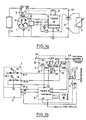
- FIG. 1a there is shown, in general, a device for supplying electrical power under high voltage to an auxiliary circuit denoted CA of a motor vehicle according to the object of the present invention.
- This device is remarkable in that it notably comprises an alternator denoted 1 with two identical stator windings, these stator windings being denoted 11 and 12.
- each stator winding is connected to a rectifier bridge denoted 13, 14 respectively delivering a rectified alternator voltage on a corresponding alternator output terminal denoted B + 1 respectively B + 2.
- the rectifier bridges 13 and 14 are not shown in FIG. La so as not to overload the drawing.
- means 3 for parallel-series / series-parallel switching of the alternator output terminals B + 1 and B + 2 are provided to generate a supply voltage of nominal value when switching above B + 1 and B + 2 in parallel.
- a supply voltage in high voltage mode is generated when the alternator output terminals B + 1 and B + 2 are switched in series.
- a control logic 4 makes it possible to control as a function of different parameters as will be described in more detail below in the description the parallel-series / series-parallel switching previously mentioned.
- the control logic 4 is interconnected with the excitation regulator 2 and the switching means 3 to ensure the conditional start-up of the high voltage regime by switching in series of the corresponding alternator output terminals B + 1 and B + 2.
- the switching means 3 in fact comprise an output terminal making it possible to deliver the supply voltage of nominal value when the switching means are in position denoted I as well as shown in Figure 1a, this nominal voltage being equal for example to 14 Volts to ensure the recharging of the battery B by interconnection via a battery terminal marked B +.
- the alternator 1 due to the series switching of the stator windings 11 and 12, on the contrary makes it possible, by its operation, to deliver a much higher voltage. higher, of the order of 70 Volts for example, at the auxiliary load denoted CA.
- the usual charge of the vehicle electrical power supply network is denoted C, this being connected between the voltage of the vehicle denoted VM and the terminal B + of the battery B .
- the auxiliary circuit CA can advantageously be constituted by a resistive element for rapid heating of the windshield of the vehicle for the purpose of defrosting the latter.
- the resistive element for rapid heating may consist of a sheet of resistive material inserted between the laminating of the windshield.
- the control logic 4 makes it possible to generate on an output terminal 40 a signal for switching on the rapid heating conditionally to values of vehicle state parameters automobile.
- vehicle state parameters of the motor vehicle can for example be the zero speed of the vehicle, the position of the clutch system in neutral. In the latter case, the neutral position of the vehicle clutch system can be advantageously detected by a detector system not shown in the drawing.
- vehicle state parameters can also be constituted by parameters of the atmospheric environment of the latter, these parameters then being able to be constituted by the outside temperature, or even the inside temperature of the vehicle with respect to a reference value. .
- FIG. 1b there is shown in more detail the interconnection of the control logic 4 with on the one hand the regulator 2 and the parallel-series / series-parallel-parallel switching means 3 of the alternator output terminals B + 1 and B + 2.
- the switching means 3 comprise for example a relay power switching 30 whose excitation coil 31 is connected between the reference voltage denoted VM or vehicle ground and the output terminal 40 of the control unit 4.
- the power switching relay 30 can comprise three input terminals 32, 33, 34, three contact blades 320, 330, 340 and six switching terminals, these switching terminals being denoted 321 , 322, 323, 324, 325, 326.
- the aforementioned contact blades denoted 320, 330, 340 ensure respectively the contact between the first input terminal 32 and the second switching terminal 322, the contact between the second input terminal 33 and the fourth switching terminal 324, the contact between the third input terminal 34 and the sixth switching terminal 326.
- the first 321, third 323, respectively fourth 324 and sixth 326 switching terminals are interconnected with one another and the fourth 324, sixth 326 switching terminals are connected to an input terminal of the switching means, this terminal input being connected to the positive terminal B + of the vehicle.
- the second 322 and the fifth 325 switching terminal are respectively connected to the ground of the vehicle VM and to the auxiliary circuit CA constituting a rapid heating circuit for the vehicle.
- the contact blades 320, 330 and 340 ensure respectively in the presence of excitations of the excitation coil 31, that is to say during the operation of the alternator in high voltage regime by switching the stator windings in series the contact between the first input terminal 32 and the first switching terminal 321, the contact between the second input terminal 33 and the second switching terminal 323, the contact between the third input terminal 34 and the fifth terminal switching 325.
- the first input terminal 32 is connected to the negative rectified alternator output terminal denoted B-2 of one of the stator windings.
- the second input terminal 33 is connected to the positive alternator output terminal B + 1 of the other stator winding of the alternator and the third input terminal 34 is connected to the rectified alternator output terminal B + 2 of the stator winding, the negative rectified alternator output terminal B-1 of the other stator winding being connected to the ground VM of the vehicle.
- the fifth switching terminal 325 delivers on series switching the voltage delivered by the alternator under high voltage conditions.
- control logic 4 comprises a circuit 41 for controlling the start of the high voltage supply, a circuit 42 for controlling the voltage input alternator rectified on the regulator, a circuit 43 for counting a predetermined duration of keeping the power supply in operation at high voltage, a circuit 44 for controlling the output of the parallel-series / series-parallel switching means.
- control logic can also include other circuits, which will be described later in the description.
- FIG. 2 a non-limiting embodiment of the various circuits previously listed 41 to 45 has been shown.
- This embodiment can be carried out using electronic components normally available on the market and by convention is designated by any resistance intended to ensure the implementation or the polarization of these components and by c any capacity or capacitor of determined value intended to ensure either the connection or the decoupling of determined terminals of these components.
- any resistance intended to ensure the implementation or the polarization of these components and by c any capacity or capacitor of determined value intended to ensure either the connection or the decoupling of determined terminals of these components.
- the respective values of these resistances r or capacitances c are different although the symbol designating them is identical, these elements strictly speaking playing no function particular vis-à-vis these components if not that of their implementation or supply according to the specifications indicated by the retailer supplying these components.
- the terminal B + of the battery is connected by means of the ignition key of the vehicle denoted K to a terminal denoted + K controlled by the ignition key.
- a filtering supply circuit denoted AF delivering at its output a continuous supply voltage denoted + Vcc, which makes it possible for example to supply the electrical energy of the various components aforementioned electronics.
- the supply voltage + Vcc can for example have the value 5 or 6 Volts.
- the circuit 41 of the high voltage power supply start control input circuit comprises, by way of nonlimiting example, a bistable flip-flop circuit denoted 410 engaged by a push button of start-up noted 411.
- the flip-flop 410 can advantageously be constituted by an integrated circuit number 4013 sold by the company MOTOROLA.
- the high-voltage power supply start-up control circuit 41 also includes a reset circuit 412 of the entire logic when the ignition key K is closed, which is constituted by three doors NAND connected in cascade, an input of the first and second NAND gate being connected to a resistance circuit r capacity c of determined time constant.
- the output of the last NAND gate constituting the reset circuit 412 is connected to the input marked RS of the flip-flop 410 by means of an OR gate with three inputs 413.
- the flip-flop 410 is connected to the operating push button 411 by its input denoted CP, the tilting input denoted S being connected by a resistor r to the ground voltage VM of the vehicle and the input of RS tilting being connected to the output of the aforementioned OR 413 gate.
- the outputs Q0 and Q0 deliver logic levels by passing from their high voltage level to their low voltage level and vice versa.
- the circuit 42 for controlling the input of the rectified alternator voltage on the regulator comprises switching means constituted by transistors T1, T2, T3 making it possible, when switching on operation of the high voltage supply by means of the operation push button 411 and of the signal delivered by the flip-flop 410 on its output Q0, the cut-off of the rectified alternator voltage delivered to the regulator on blocking of the transistor T3.
- the transistor T3 In the absence of actuation of the operating push button 411 and of a corresponding signal on the output Q0 of the flip-flop 410, the transistor T3 is normally conductive and delivers to the rectified alternator voltage input of the regulator, that is to say - say on the input marked SE of the regulator the battery voltage delivered by terminal B + thereof.
- the transistors T1, T2 and T3 are connected in cascade, the transistor T3 thus constituting the output stage making it possible to apply the nominal battery voltage delivered by the terminal B + to the input SE of the regulator.
- the rectifier alternator voltage input control circuit 42 on the regulator includes switching means constituted by the transistors T4, T5, T6.
- the collector terminal of the transistor T1 is connected to the + K terminal of the ignition key, i.e. to the B + terminal of the battery when the ignition key K is actuated, this connection being effected by the through an LT indicator lamp.
- the transistor T2 is mounted as a common emitter and the transistor T3 is constituted by a transistor of the complemented type, that is, in the embodiment shown in FIG. 2, by a PNP transistor whose emitter is directly connected to the aforementioned terminal B +, the collector being connected to the input terminal SE of the regulator.
- the transistors T5 and T4 are connected in cascade, the transistor T4 being constituted by a PNP transistor whose emitter is connected to the connection terminal of the auxiliary load CA, the collector of this same transistor T4 being connected to the terminal SE input of the regulator via an adjustable resistor R1 and a ballast resistor R2.
- the base of the transistor T4 is connected to the collector of the transitor T5, which, consisting of an NPN transistor, has its collector connected to the ground voltage VM of the device.
- the base of transistor T6 is connected to the collector of transistor T5 via a first diode D1 directly biased and the collector of transistor T6 is connected to the input terminal SE of the regulator via a diode D2 polarized in the forward direction.
- the transistors T4, T5, T6 allow on command of saturation of the transistor T5 and of the transisitor T4 to deliver a reduced rectified alternator voltage, the voltage on the supply terminal of the auxiliary load + AC reaching the value of the voltage in operating mode.
- high voltage ie 70 Volts
- the value of the alternator voltage rectified at point SE substantially corresponding to that of the alternator voltage rectified in nominal mode.
- the circuit 45 for controlling the input of the alternator voltage rectified on the regulator comprises a flip-flop 450 formed by an integrated circuit sold under the reference 4013 by the company MOTOROLA.
- the flip-flop 450 is triggered after time delay following the actuation of the push button 411 as will be described later in the description, the control output Q of the flip-flop 450 making it possible to control the switching of the transistor T5 of the circuit of input control 42 of the rectified alternator voltage on the regulator.
- the circuit 45 for controlling the input of the alternator voltage rectified on the regulator comprises, in addition to the flip-flop 450, an OR gate with three inputs 451, the output is connected to the RS tilting terminal of the flip-flop 450, the tilting terminal S being connected to the ground voltage via a resistor.
- the circuit 43 for counting for a predetermined period and for keeping the high voltage supply in operation includes, as shown in FIG. 2, a first timing circuit 430 allowing, after a first timing noted ⁇ 1 of determined duration, the switching means to be engaged by excitation of the excitation coil.
- the first delay circuit allows following a second delay ⁇ 2 the saturation control of the transistors T4, T5, T6 of the input control circuit 42 of the alternator voltage rectified on the regulator.
- the first timing circuit 430 is constituted by an integrated circuit sold under the reference 4060 by the company MOTOROLA.
- This integrated circuit consists of a set of flip-flops, the common RS switching input of which is connected to the output of an OR gate 431 with three inputs, the QB output of the flip-flop thus formed and forming the first timer circuit 430 being connected to the input CP of the flip-flop 450 constituting the circuit 45 for controlling the input of the rectified alternator voltage on the regulator.
- a second timing circuit 431 is provided to constitute the circuit 43 for counting a predetermined duration for keeping the high voltage supply in operation.
- This second timing circuit 431 making it possible to define the duration of maintenance of the high voltage supply over a supply duration ⁇ 3. It allows at the end of this duration ⁇ 3 to reset the first timing circuit 430 via the assembly 433 and the stopping of the high voltage supply according to a cycle reusing the first timings ⁇ 1, ⁇ 2 to obtain the switching of the relay 30 in the absence of current in the contacts.
- the second transport circuit 431 can be constituted by an integrated circuit marketed under the reference 4521 by the company MOTOROLA.
- the RS tilting input of the above-mentioned integrated circuit is connected to the output Q0 of the flip-flop 410 of the circuit 41 of the high voltage supply start-up control input circuit.
- the output Q of the integrated circuit constituting the second timing circuit 431 is connected to the RS input of the first timing circuit 430 by means of a part of an OR gate with three inputs 432 and a switching circuit.
- signal form 433 consisting of three NAND gates connected in cascade, the first two NAND gates having one of their inputs connected to a capacity resistance circuit of the integrator type, these capacity resistance circuits being themselves connected to the output Q of the second timing circuit 431.
- the circuit 44 for controlling the output of the parallel-series / series-parallel switching means comprises a flip-flop 440 which receives from the first timing circuit 430 a control signal.
- This control signal is constituted by the signal delivered by the output QA of the first timing circuit 430, this output being connected to the input CP of the bistable circuit 440.
- the bistable circuit 440 can advantageously consist of an integrated circuit marketed under the reference 4013 by MOTOROLA.
- the tilting input terminal S of this bistable circuit is connected to the ground voltage by a resistor r and the tilting terminal RS is connected to the output Q0 of the flip-flop 410 via an OR gate with two inputs 442.
- the output terminal Q is connected to a second input of the OR gate 413 with three inputs of the high voltage power supply start command circuit 41 via an AND gate with three inputs 441.
- the output terminal Q of the flip-flop 440 is connected to a power circuit constituted by two transistors T7 and T8.
- the transistor T8 is for example a PNP transistor whose collector electrode is directly connected to the + K terminal of the ignition key K of the vehicle and whose collector is directly charged by the excitation winding 31 or the exciter coil of the relay parallel-series / series-parallel switching means.
- the transistor T7 is constituted by an NPN transistor whose emitter is connected to the ground voltage VM of the vehicle and whose collector is connected via polarization resistors r to the + K terminal of the vehicle ignition key , the base of transistor T8 being connected at an intermediate point of the above-mentioned resistor bridge r.
- the base of transistor T7 is connected to the output Q of the bistable circuit 440.
- the control logic 4 also includes a circuit 47 for controlling input for stopping the high voltage supply.
- this circuit advantageously includes a flip-flop rated 470 constituted by an integrated circuit marketed under the reference 4013 by the company MOTOROLA.
- the RS tilting input of this bistable circuit 470 is connected to the output Q0 of the flip-flop 410 of the circuit 41 of the high voltage supply start-up control input circuit.
- the tilting input S of the flip-flop 470 is connected to the ground voltage of the device by a bias resistor r and the input CP of the flip-flop 470 is connected to a stop push button noted 471 by the intermediate of a bias resistor r and a decoupling capacitor denoted c.
- the link between the counting circuit 43 of a predetermined duration, the control output circuit 44 of the switching means parallel-series / series-parallel, the circuit 45 for controlling the input of the alternator voltage rectified on the regulator and the circuit 47 for controlling the stopping of high voltage supply is produced by means of an OR gate 500 and an AND gate 501.
- the OR gate 500 receives on a first input the output Q of the flip-flop 470 and on a second input the output Q of the flip-flop 431 constituting the second time delay means.
- the output of the OR gate 500 is connected to one of the inputs of the AND gate 501 with three inputs.
- Another input of the AND gate 501 is connected to the output terminal QA of the flip-flop 430 constituting the first delay means.
- the last input of gate ET 501 is itself connected to the output Q of the monostable lever 450 of the circuit 45 for controlling the input of the alternator voltage rectified on the regulator by means of a capacity resistance circuit of integrator type denoted rc.
- the output of the AND gate 501 is connected to an input of the OR gate 442, the output of which is itself connected to the input of the RS tilting input of the flip-flop 440 of the circuit 44 for controlling the means output parallel-series / series-parallel switching.
- the control logic 4 also includes a circuit 46 for detecting temperature and engine speed.
- This circuit advantageously comprises a first comparator 460 receiving on a positive terminal a reference voltage Vr1 and on its negative terminal a voltage representative of the minimum operating voltage.
- the output of the first comparator 460 is connected to an OR gate 463, the output of which is itself connected to the third OR gate 413 of the circuit 41 for inputting control and switching on the high voltage supply.
- the temperature detection circuit 46 further comprises a second comparator 461 receiving on a positive terminal the reference voltage Vr1 and on its negative terminal a voltage representative of the ambient temperature or of the internal temperature of the vehicle from a resistive bridge comprising a resistance with temperature coefficient 462 and calibration resistors R2 and R3.
- the output of comparator 461 forming a second comparator is connected to another input of the OR gate 463.
- the letters a, d, k designate respectively the functional variables with defrost stop or rapid heating, defrost or rapid heating request, k actuation of the vehicle ignition key, the letters or complementary variables representing of course the absence of these states.
- Position 1001 represents the initial position according to which the vehicle is stopped in the absence of any request for rapid heating. Following the closing of the ignition key K, position 1002 represents the following state according to which the vehicle is stopped but the vehicle engine being started. In this position, the transistor T3 then conductive via the transistors T1 and T2, the terminal SE of the regulator receives the voltage delivered by the terminal B + of the battery. The reset circuit 412 generates a pulse, which is transmitted in the OR gate 413 and causes the reset of the flip-flop 410, the transistor T3 always being of course maintained in the conduction state. On request for rapid heating or defrosting, position 1003 is reached, the variable d being equal to 1, by actuation of the operating push button 411.
- position 1004 is reached in which on tilting of the rocker bistable 410 and by the transistor T1 and the transistor T2, the transistor T3 is blocked, which has the effect of cutting the voltage on the input SE of the regulator.
- the indicator lamp LT controlled by the transistor T1 lights up to indicate the start of the rapid heating circuit.
- the two timing circuits 430 and 431 begin to count down respectively the first time delay ⁇ 1 equal for example to 400 milliseconds and the third time delay ⁇ 3 equal for example to 5 minutes, duration of rapid heating.
- the position 1005 is reached, the output Q of the first time delay circuit 430 driving through the flip-flop 440 the supply of the excitation coil 31 and therefore the activation of the relay of parallel-series / series-parallel switching.
- the first delay circuit 430 allows, following a second delay ⁇ 2 equal for example to 400 milliseconds, to carry out the saturation control of the transistors T4, T5, T6 of the control circuit of the alternator voltage rectified on the regulator, this position being reached in 1006 where the resistors R1, R2 are then connected in series with the input terminal SE of the regulator, the voltage delivered by the alternator then being equal to 70 Volts.
- the time delay ⁇ 3 making it possible to define the duration of maintenance of the high voltage supply is counted down by the second time delay circuit 431.
- the connection of the resistors R1 and R2 in series with the input terminal SE of the regulator has the effect of allowing the corresponding operation of the alternator in high voltage regime, the voltage applied to the input terminal SE of the regulator being close to the nominal voltage of 14 Volts because of the voltage drop in resistors R1 and R2.
- the voltage delivered by the alternator is equal to 70 Volts and the auxiliary load AC of the vehicle is thus subjected to the so-called rapid heating regime.
- the second time delay circuit 431 delivers its switching information, which is transformed into pulses by circuit 433, which has the effect of resetting the first time delay circuit 430 as well as the control circuit 45 alternator voltage input rectified on the regulator via the flip-flop 450.
- This position is reached in FIG. 3 at 1007 and the tilting of the aforementioned bistable ball 450 has the effect of causing the connected circuit to break through the transistor T5 and the transistor T4. to the SE input terminal of the regulator.
- the timer circuit 430 previously reset to zero by the second timer circuit 431 at the end of the timer ⁇ 3 equal to 500 minutes delivers on its output terminal QB a switching voltage, which via the OR gate 441 and the OR gate 413 has the effect of resetting the bistable circuit 410 to zero.
- the direct connection of the terminal SE for input of the alternator voltage to the regulator is then carried out on the terminal B + of the battery via of transistor T1, the power supply to the excitation coil 31 having been cut off beforehand by resetting the bistable circuit 440 and this position being reached in position denoted 1008 in FIG. 3.
Landscapes
- Engineering & Computer Science (AREA)
- Power Engineering (AREA)
- Control Of Charge By Means Of Generators (AREA)
- Control Of Eletrric Generators (AREA)
Applications Claiming Priority (2)
| Application Number | Priority Date | Filing Date | Title |
|---|---|---|---|
| FR8805163A FR2630271B1 (fr) | 1988-04-19 | 1988-04-19 | Dispositif d'alimentation electrique sous tension elevee du circuit auxiliaire d'un vehicule automobile |
| FR8805163 | 1988-04-19 |
Publications (1)
| Publication Number | Publication Date |
|---|---|
| EP0338926A1 true EP0338926A1 (de) | 1989-10-25 |
Family
ID=9365446
Family Applications (1)
| Application Number | Title | Priority Date | Filing Date |
|---|---|---|---|
| EP19890401093 Withdrawn EP0338926A1 (de) | 1988-04-19 | 1989-04-19 | Vorrichtung zur Hochspannungsstromversorgung des Betriebsstromkreises eines Kraftfahrzeuges |
Country Status (3)
| Country | Link |
|---|---|
| US (1) | US4967137A (de) |
| EP (1) | EP0338926A1 (de) |
| FR (1) | FR2630271B1 (de) |
Cited By (9)
| Publication number | Priority date | Publication date | Assignee | Title |
|---|---|---|---|---|
| EP0407640A1 (de) * | 1989-07-13 | 1991-01-16 | Nissan Motor Co., Ltd. | Windschutzscheibenheizung für Fahrzeuge |
| EP0407641A1 (de) * | 1989-07-13 | 1991-01-16 | Nissan Motor Co., Ltd. | Erwärmungsvorrichtung fÀ¼r Fahrzeugscheibe |
| EP0371472A3 (de) * | 1988-11-29 | 1991-05-15 | Nissan Motor Co., Ltd. | Elektrisches System für ein Kraftfahrzeug |
| EP0446184A1 (de) * | 1990-03-07 | 1991-09-11 | INDUSTRIE MAGNETI MARELLI S.p.A. | Elektrisches System für ein Fahrzeug mit einer Vorrichtung zum Enteisen der Windschutzscheibe und/oder des Rückfensters |
| EP0402040A3 (de) * | 1989-06-06 | 1991-11-06 | Isuzu Motors Limited | Enteisungsvorrichtung für Kraftfahrzeuge |
| EP0569279A1 (de) * | 1992-05-07 | 1993-11-10 | Valeo Equipements Electriques Moteur | Vorrichtung zur Stromversorgung eines Hilfstromkreises eines Kraftfahrzeuges mit erhöhter Spannung |
| EP0711017A1 (de) * | 1994-11-03 | 1996-05-08 | General Motors Corporation | Nullstromschaltung für geteilte Statorwicklungen einer Wechselstrommaschine mit Dauermagnet |
| EP0723327A1 (de) * | 1995-01-23 | 1996-07-24 | Valeo Equipements Electriques Moteur | Gesicherte Stromversorgungsvorrichtung für die Nebenschaltungen eines Fahrzeuges insbesondere für beheizbare Windschutzscheibe unter zeitweiligem Überspannungszustand |
| EP0724321A3 (de) * | 1995-01-25 | 1998-05-20 | Mitsubishi Denki Kabushiki Kaisha | Steuerungsvorrichtung für Kraftfahrzeugswechselstromgenerator |
Families Citing this family (9)
| Publication number | Priority date | Publication date | Assignee | Title |
|---|---|---|---|---|
| DE3919563A1 (de) * | 1989-06-15 | 1990-12-20 | Bosch Gmbh Robert | Elektrische fahrzeugheizung |
| JPH03294660A (ja) * | 1990-04-11 | 1991-12-25 | Mitsubishi Electric Corp | エンジン始動補助装置 |
| US5321231A (en) * | 1992-01-24 | 1994-06-14 | General Motors Corporation | System for supplying power to an electrically heated catalyst |
| US5632917A (en) * | 1994-08-08 | 1997-05-27 | Ford Motor Company | Electric windshield defroster |
| US5920165A (en) * | 1998-04-09 | 1999-07-06 | Ut Automotive Dearborn, Inc. | Bi-directional motor control incorporating a defroster element |
| US6066941A (en) * | 1998-07-10 | 2000-05-23 | Outboard Marine Corporation | Switching alternator system |
| US7026794B1 (en) | 2004-02-06 | 2006-04-11 | Brp Us Inc. | Dynamically controlled switching alternator system |
| US8072092B2 (en) * | 2009-07-24 | 2011-12-06 | C.E. Niehoff & Co. | System and method for sequentional electrical power delivery from two generators in a vehicle electrical system |
| JP6543294B2 (ja) * | 2017-03-24 | 2019-07-10 | 矢崎総業株式会社 | 温度検出装置 |
Citations (5)
| Publication number | Priority date | Publication date | Assignee | Title |
|---|---|---|---|---|
| US3469073A (en) * | 1964-06-22 | 1969-09-23 | Gen Motors Corp | Electrical system |
| GB1483033A (en) * | 1976-02-11 | 1977-08-17 | Ford Motor Co | Vehicle window heating circuit |
| WO1984003595A1 (en) * | 1983-03-09 | 1984-09-13 | Ayr Pty Ltd | Electrical power supply for a motor vehicle |
| EP0246976A1 (de) * | 1986-05-23 | 1987-11-25 | Valeo Equipements Electriques Moteur | Stromversorgungsvorrichtung für die Nebenschaltungen eines Fahrzeuges unter zeitweiligem Überspannungszustand |
| EP0286510A1 (de) * | 1987-03-31 | 1988-10-12 | Valeo Equipements Electriques Moteur | Elektrische Stromversorgungsvorrichtung durch Überspannung |
Family Cites Families (6)
| Publication number | Priority date | Publication date | Assignee | Title |
|---|---|---|---|---|
| US3585358A (en) * | 1969-07-24 | 1971-06-15 | Motorola Inc | Automotive quick heat system |
| US3668419A (en) * | 1970-12-30 | 1972-06-06 | Motorola Inc | Electrical power source and heat augmentation system for use in automotive vehicles |
| JPS5223308U (de) * | 1975-08-09 | 1977-02-18 | ||
| US4009431A (en) * | 1975-09-08 | 1977-02-22 | General Motors Corporation | Series parallel transition for power supply |
| IT1144426B (it) * | 1981-07-23 | 1986-10-29 | Marelli Autronica | Alternatore particolarmente per autoveicoli |
| US4730097A (en) * | 1986-08-15 | 1988-03-08 | General Motors Corporation | Dual mode windshield heater control |
-
1988
- 1988-04-19 FR FR8805163A patent/FR2630271B1/fr not_active Expired - Lifetime
-
1989
- 1989-04-18 US US07/340,030 patent/US4967137A/en not_active Expired - Lifetime
- 1989-04-19 EP EP19890401093 patent/EP0338926A1/de not_active Withdrawn
Patent Citations (5)
| Publication number | Priority date | Publication date | Assignee | Title |
|---|---|---|---|---|
| US3469073A (en) * | 1964-06-22 | 1969-09-23 | Gen Motors Corp | Electrical system |
| GB1483033A (en) * | 1976-02-11 | 1977-08-17 | Ford Motor Co | Vehicle window heating circuit |
| WO1984003595A1 (en) * | 1983-03-09 | 1984-09-13 | Ayr Pty Ltd | Electrical power supply for a motor vehicle |
| EP0246976A1 (de) * | 1986-05-23 | 1987-11-25 | Valeo Equipements Electriques Moteur | Stromversorgungsvorrichtung für die Nebenschaltungen eines Fahrzeuges unter zeitweiligem Überspannungszustand |
| EP0286510A1 (de) * | 1987-03-31 | 1988-10-12 | Valeo Equipements Electriques Moteur | Elektrische Stromversorgungsvorrichtung durch Überspannung |
Cited By (11)
| Publication number | Priority date | Publication date | Assignee | Title |
|---|---|---|---|---|
| EP0371472A3 (de) * | 1988-11-29 | 1991-05-15 | Nissan Motor Co., Ltd. | Elektrisches System für ein Kraftfahrzeug |
| EP0402040A3 (de) * | 1989-06-06 | 1991-11-06 | Isuzu Motors Limited | Enteisungsvorrichtung für Kraftfahrzeuge |
| EP0407640A1 (de) * | 1989-07-13 | 1991-01-16 | Nissan Motor Co., Ltd. | Windschutzscheibenheizung für Fahrzeuge |
| EP0407641A1 (de) * | 1989-07-13 | 1991-01-16 | Nissan Motor Co., Ltd. | Erwärmungsvorrichtung fÀ¼r Fahrzeugscheibe |
| EP0446184A1 (de) * | 1990-03-07 | 1991-09-11 | INDUSTRIE MAGNETI MARELLI S.p.A. | Elektrisches System für ein Fahrzeug mit einer Vorrichtung zum Enteisen der Windschutzscheibe und/oder des Rückfensters |
| EP0569279A1 (de) * | 1992-05-07 | 1993-11-10 | Valeo Equipements Electriques Moteur | Vorrichtung zur Stromversorgung eines Hilfstromkreises eines Kraftfahrzeuges mit erhöhter Spannung |
| FR2691021A1 (fr) * | 1992-05-07 | 1993-11-12 | Valeo Equip Electr Moteur | Dispositif d'alimentation électrique sous tension élevée d'un circuit auxiliaire d'un véhicule automobile. |
| EP0711017A1 (de) * | 1994-11-03 | 1996-05-08 | General Motors Corporation | Nullstromschaltung für geteilte Statorwicklungen einer Wechselstrommaschine mit Dauermagnet |
| EP0723327A1 (de) * | 1995-01-23 | 1996-07-24 | Valeo Equipements Electriques Moteur | Gesicherte Stromversorgungsvorrichtung für die Nebenschaltungen eines Fahrzeuges insbesondere für beheizbare Windschutzscheibe unter zeitweiligem Überspannungszustand |
| FR2729798A1 (fr) * | 1995-01-23 | 1996-07-26 | Valeo Equip Electr Moteur | Dispositif securise d'alimentation electrique en regime temporaire de surtension de circuits auxiliaires d'un vehicule automobile, notamment d'un pare-brise chauffant |
| EP0724321A3 (de) * | 1995-01-25 | 1998-05-20 | Mitsubishi Denki Kabushiki Kaisha | Steuerungsvorrichtung für Kraftfahrzeugswechselstromgenerator |
Also Published As
| Publication number | Publication date |
|---|---|
| FR2630271B1 (fr) | 1991-10-11 |
| US4967137A (en) | 1990-10-30 |
| FR2630271A1 (fr) | 1989-10-20 |
Similar Documents
| Publication | Publication Date | Title |
|---|---|---|
| FR2630271A1 (fr) | Dispositif d'alimentation electrique sous tension elevee du circuit auxiliaire d'un vehicule automobile | |
| EP0246976B1 (de) | Stromversorgungsvorrichtung für die Nebenschaltungen eines Fahrzeuges unter zeitweiligem Überspannungszustand | |
| EP0110775A1 (de) | Regulierungseinrichtung mit kleiner Verlustspannung | |
| EP0911953A1 (de) | Regelvorrichtung für den Anlasser eines Kraftfahrzeuges | |
| FR2829308A1 (fr) | Systeme d'alimentation electrique pour demarreur de moteur | |
| EP0796992B1 (de) | Verfahren und Vorrichtung zum Steuern eines Versorgungsschalters für einen Kraftfahrzeuganlasser | |
| FR3093248A1 (fr) | Système et procédé de précharge d’un condensateur par une batterie comportant une résistance de précharge et un dispositif hacheur | |
| FR2685142A1 (fr) | Montage d'un circuit pour commander le fonctionnement de repos d'un dispositif de commande d'un vehicule automobile. | |
| FR2960265A1 (fr) | Dispositif de demarrage de moteur thermique | |
| FR2520890A1 (fr) | Dispositif de controle de la vitesse d'embrayage d'un embrayage electromagnetique | |
| EP0286510B1 (de) | Elektrische Stromversorgungsvorrichtung durch Überspannung | |
| FR2870986A1 (fr) | Dispositif de commande de relais pour appareil electrique en courant continu | |
| EP0163332B1 (de) | Statisches Relais für Gleichstrom | |
| FR2757220A1 (fr) | Perfectionnements aux procedes et aux systemes pour la commande de l'arret automatique d'un demarreur de vehicule automobile | |
| FR2751145A1 (fr) | Dispositif de controle de la charge d'un supercondensateur et procede de commande d'un tel dispositif | |
| WO1999048183A1 (fr) | Bloc de moteur electrique, notamment pour vehicule automobile, integrant une electronique de commande | |
| EP0164770B1 (de) | Statisches Relais für niedrige Gleichstromspannung | |
| EP2991225A1 (de) | Statisches steuerrelais eines elektrischen anlassers eines kraftfahrzeugs, und entsprechender elektrischer anlasser eines kraftfahrzeugs | |
| EP3894278B1 (de) | Vorrichtung zum vorladen eines stromnetzes | |
| FR2654880A1 (fr) | Circuit integre de puissance "intelligent" du type mos, pour la commande de l'alimentation d'une charge electrique. | |
| FR2505935A1 (fr) | Installation d'allumage pour un moteur a combustion interne | |
| EP0819945A1 (de) | Messanordnung zum Messen der Dauer eines Stromversorgungsausfalls eines elektronischen Systems | |
| EP0176434B1 (de) | Einrichtung zur Steuerung der Verriegelung von Türen und anderer beweglicher Platten eines Automobils | |
| EP1462645B1 (de) | Vorrichtung zur Steuerung eines Anlassers eines Kraftfahrzeuges | |
| EP1642764B1 (de) | Vorrichtung zur Regelung von Elektrischen Speichernmitteln von Hybridantriebmitteln |
Legal Events
| Date | Code | Title | Description |
|---|---|---|---|
| PUAI | Public reference made under article 153(3) epc to a published international application that has entered the european phase |
Free format text: ORIGINAL CODE: 0009012 |
|
| AK | Designated contracting states |
Kind code of ref document: A1 Designated state(s): DE SE |
|
| 17P | Request for examination filed |
Effective date: 19900129 |
|
| 17Q | First examination report despatched |
Effective date: 19920409 |
|
| STAA | Information on the status of an ep patent application or granted ep patent |
Free format text: STATUS: THE APPLICATION IS DEEMED TO BE WITHDRAWN |
|
| 18D | Application deemed to be withdrawn |
Effective date: 19920820 |