EP0018656A1 - Balance utilisable dans des zônes à danger d'explosion - Google Patents
Balance utilisable dans des zônes à danger d'explosion Download PDFInfo
- Publication number
- EP0018656A1 EP0018656A1 EP80102406A EP80102406A EP0018656A1 EP 0018656 A1 EP0018656 A1 EP 0018656A1 EP 80102406 A EP80102406 A EP 80102406A EP 80102406 A EP80102406 A EP 80102406A EP 0018656 A1 EP0018656 A1 EP 0018656A1
- Authority
- EP
- European Patent Office
- Prior art keywords
- pressure
- resistant housing
- housing
- weighing system
- plunger
- Prior art date
- Legal status (The legal status is an assumption and is not a legal conclusion. Google has not performed a legal analysis and makes no representation as to the accuracy of the status listed.)
- Granted
Links
Images
Classifications
-
- G—PHYSICS
- G01—MEASURING; TESTING
- G01G—WEIGHING
- G01G21/00—Details of weighing apparatus
- G01G21/24—Guides or linkages for ensuring parallel motion of the weigh-pans
- G01G21/244—Guides or linkages for ensuring parallel motion of the weigh-pans combined with flexure-plate fulcrums
-
- G—PHYSICS
- G01—MEASURING; TESTING
- G01G—WEIGHING
- G01G21/00—Details of weighing apparatus
- G01G21/28—Frames, Housings
Definitions
- the invention relates to a balance with a housing enclosing the weighing system, with an electrical or electronic display device and with a weighing pan that receives the goods to be weighed, which can be moved in the vertical direction to a limited extent and is supported on the weighing system.
- the electro-mechanical scales in use today have extensive electrics and electronics, which on the one hand allow the weighing goods to be weighed quickly and conveniently, but on the other hand involve the risk of igniting sparks and short circuits when the scale is in rooms used with an explosive atmosphere or weighing goods to be weighed with the balance.
- the weighing pan receiving the goods to be weighed is supported on the weighing system, which is arranged in an enclosing housing.
- the weighing pan support penetrates the housing without contact. The result
- the annular gap formed is only sealed by a labyrinth seal, so that the weighing pan support can move vertically limited by stops, but is otherwise guided through the housing without friction.
- the lamp of the lighting device is housed in a protective housing arranged in the scale housing and connected to the lighting network via a voltage-reducing stray transformer arranged in the scale housing, which can be switched on and off on the primary side by an explosion protection switch arranged in the scale housing.
- the invention is therefore based on the object of providing an electro-mechanical or electronic balance of conventional design with explosion protection without the weighing comfort inherent in these balances being impaired.
- a commercially available balance is enclosed in a pressure-resistant housing, which has a defined strength against a defined explosion pressure coming from the inside, that a weighing pan is provided outside the pressure-resistant housing, which is on a Supporting the linkage, wherein the linkage pierces the pressure-resistant housing in a closely enclosing and relatively long opening without contact, is guided in parallel in the vertical direction and is on the weighing system supports that a pressure-resistant viewing window made of transparent material is also provided in the area of the display device in the pressure-resistant housing and that the electrical supply lines are inserted explosion-proof into the pressure-resistant housing.
- the plunger has its own parallel guide, which is partly outside and partly inside the flameproof housing is provided so that the overall height of the entire device can be kept relatively low.
- the vertically movable parts that are supported on the weighing system are held in a position that does not stress the weighing system by a dead load spring that can be set outside the pressure-resistant housing.
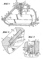
- a standard electronic precision balance 1 of the applicant is housed in a surrounding, pressure-resistant housing 3, 4, which consists of a cover part 3 and a base part 4, which have circumferential flanges which are fixed to one another by means of a plurality of screws 5 or other clamping means are connected.
- the scale 1 has, in a known manner, a large number of electronic components and a transformer which are fed from the outside via the electrical cable 32, the Cable 32 short-circuit and fail-safe and is inserted through the cable bushing 31 into the pressure-resistant housing 3.4.
- the weighing system of the scale 1 can work, for example, according to the principle of electromagnetic force compensation and ends with its load receiver 2 on the top of the scale 1 and normally picks up a load pan.
- the invention is shown on an upper-pan scale, but it is possible to use the same principle for a lower-pan scale.
- the parallel guide described below is arranged in the bottom part 4 of the pressure-resistant housing 3, 4.
- On the weighing system 2 is supported by balls 11 and ball pans 12, the linkage formed from the adapter 10 and plunger 9 for the actual weighing pan 6.
- the plunger 9 passes through the cover part 3 of the pressure-resistant housing without contact, an annular gap of approximately 25 mm in length and 0.2 mm in width being formed between the housing part 3 and the plunger 9.
- the plunger 9 is guided in parallel with the aid of an upper link 13 and a lower link 14, the upper link 13 and lower link 14 having articulated points 33 in a known manner, which in the area of the Provided on the tappet 9 and in the area of the clamping points of the fixed points 16 of the cover part 3 are.
- the possible vertical movement of the load shell 6 and the plunger 9 is limited by stops 8 and is a few tenths of a mm.
- the upper link 13 is covered with a protective hood 7, which ends in the region of the plunger 9 in a collar 18 and forms a labyrinth seal with a further collar 18 of the plunger 9, with which the penetration of foreign bodies into the weighing system is prevented.
- the plunger 9 also has a bracket 19 on which a dead load spring 17 engages, which on the other hand is attached to a gallows 34 of the housing cover 3 and with the help of which the vertically movable parts such as plunger 9, parallel guide 13, 14 and weighing pan 6 in a position that does not stress the weighing system 2.
- the adjustment can be carried out at any time by means of the setting means located outside of the pressure-resistant housing 3, 4, without additional adjustment of the balance 1, which is located in the pressure-proof housing 3, 4, having to take place.
- a viewing window 23 is provided in the cover part 3, which is also designed to be pressure-resistant with the aid of a transparent pane 24 made of tempered glass.
- the bulletproof glass 24 is supported in a circumferential inner fold 25, a lead sealing frame 26 being provided as a seal and lining between the inner fold 25 and the bulletproof glass 24 and a lead frame 29 made of lead between the bulletproof glass 24 and a clamping frame 27.
- the bulletproof glass pane 24 is clamped in the inner fold 25 with the aid of screws 28 and the clamping frame 27.
- FIG. 2 shows a variant of the connection of the plunger 9, adapter 10 and weighing system 2 already shown in FIG. 1.
- the adapter 10 is mounted in a blind hole 21 which is open towards the weighing system 2 and is likewise articulated with balls 11 and ball sockets 12 the plunger 9 and the weighing system 2 coupled.
- the scale 1 is immovably fixed in the base part 4 with the help of the supports 30, so that the pressure-resistant housing 3, 4 with the internal scale 1 can also be safely transported without the risk that the balance 1 slides back and forth within the pressure-resistant housing 3, 4;
- a rigid connection between the plunger 9 and the weighing system 2 would damage the same or the parallel guide 13, 14.
- the adapter 10 Due to the articulated mounting and interposition of the adapter 10 with the help of the balls and ball pans, the adapter 10 has the possibility of pivoting slightly transversely to its vertical axis about the respective ball pivot point, without this having any harmful effects on the weighing system 2.
- the blind hole 21 is accordingly kept somewhat larger in diameter than the diameter of the adapter 10. In the embodiment according to FIG. 1, the adapter 10 can migrate slightly to the side in the same way.
- the overall height of the pressure-resistant housing 3.4 " can be reduced in that the upper link 13 is arranged outside the cover part 3 and that, according to FIG. 2, the adapter 10 is incorporated in a blind hole 21 of the plunger 9.
- the inner contour shape of the pressure-resistant housing 3, 4 is preferably matched to that of a hollow ball or an elongated depression in order to ensure a favorable pressure distribution.
- additional electronics can be housed explosion-proof z.
- Scales with higher loads are mostly designed as so-called weighbridges.
- a rectangular load pan is supported at the four corner points on a bridge of the weighing system (e.g. GB-PS 1369035).
- the parallel guide shown in Fig. 1 and.2 can also be used for such weighbridges.
- the adapter 10 can either merge into a rigid distribution cross, the ends of which are supported on the bridge of the weighing system, or each corner point of the bridge is loaded by a separate plunger with parallel guide, which is guided through the housing 3, 4 analogously to FIG. 1.
- the external load pan is adapted to the load pan of the weighbridge and is supported either via a distributor cross on the central plunger or at the four corner points on the four plungers with parallel guidance.
Landscapes
- Physics & Mathematics (AREA)
- General Physics & Mathematics (AREA)
- Measuring Fluid Pressure (AREA)
- Arrangements For Transmission Of Measured Signals (AREA)
- Casings For Electric Apparatus (AREA)
Applications Claiming Priority (2)
| Application Number | Priority Date | Filing Date | Title |
|---|---|---|---|
| DE7913203U | 1979-05-08 | ||
| DE19797913203U DE7913203U1 (de) | 1979-05-08 | 1979-05-08 | Waage |
Publications (2)
| Publication Number | Publication Date |
|---|---|
| EP0018656A1 true EP0018656A1 (fr) | 1980-11-12 |
| EP0018656B1 EP0018656B1 (fr) | 1983-07-27 |
Family
ID=6703780
Family Applications (1)
| Application Number | Title | Priority Date | Filing Date |
|---|---|---|---|
| EP80102406A Expired EP0018656B1 (fr) | 1979-05-08 | 1980-05-03 | Balance utilisable dans des zônes à danger d'explosion |
Country Status (3)
| Country | Link |
|---|---|
| US (1) | US4320809A (fr) |
| EP (1) | EP0018656B1 (fr) |
| DE (2) | DE7913203U1 (fr) |
Cited By (6)
| Publication number | Priority date | Publication date | Assignee | Title |
|---|---|---|---|---|
| FR2506013A1 (fr) * | 1981-05-13 | 1982-11-19 | Sartorius Gmbh | Balance electromecanique, notamment pour atmospheres a risques d'explosion |
| FR2555314A1 (fr) * | 1983-11-21 | 1985-05-24 | Kubota Ltd | Capteur d'effort a fonction antideflagration |
| GB2165656A (en) * | 1984-10-17 | 1986-04-16 | Sartorius Gmbh | Electronic weighing machine |
| EP0327182A1 (fr) * | 1988-02-05 | 1989-08-09 | Tec-Keylard Weegschalen Nederland B.V. | Comptoir pour marchandises avec un dispositif électronique de pesage |
| EP0362567A3 (fr) * | 1988-09-07 | 1991-04-10 | Ishida Scales Mfg. Co., Ltd. | Dispositif étanche pour le pesage automatique |
| DE10025712A1 (de) * | 2000-05-25 | 2001-12-06 | Mettler Toledo Gmbh | Waage mit Überdruckgehäuse |
Families Citing this family (13)
| Publication number | Priority date | Publication date | Assignee | Title |
|---|---|---|---|---|
| JPS59145922A (ja) * | 1983-02-09 | 1984-08-21 | Shimadzu Corp | 電子天びん |
| US4492280A (en) * | 1983-02-28 | 1985-01-08 | Masstron Scale Inc. | Weighing apparatus including load cells with intrinsic safety barrier |
| JP2000241260A (ja) * | 1999-02-22 | 2000-09-08 | Japan Atom Energy Res Inst | 力・荷重測定器 |
| DE10149606C2 (de) * | 2001-10-09 | 2003-12-24 | Mettler Toledo Gmbh | Labyrinthdichtung mit lösbarem Ringelement und Waage |
| US20080230282A1 (en) * | 2005-08-05 | 2008-09-25 | Weightech, Inc. | Modular sealed portable digital electronic controller |
| US7002084B2 (en) * | 2002-01-16 | 2006-02-21 | Weightech, Inc. | Modular sealed portable digital electronic controller |
| DE10253601B4 (de) † | 2002-11-15 | 2013-11-07 | Mettler-Toledo Ag | Wägemodul mit Vorrichtung zur Staubentfernung |
| US7710714B2 (en) * | 2004-09-13 | 2010-05-04 | Bettcher Industries, Inc. | Housing for scale or load cell controller |
| EP1938058B1 (fr) * | 2005-10-12 | 2016-04-20 | Wipotec Wiege- und Positioniersysteme GmbH | Cellule de pesage avec support de reception |
| DE102005055754B4 (de) * | 2005-11-21 | 2016-10-20 | Wipotec Wiege- Und Positioniersysteme Gmbh | Aufnahme für das Antriebsaggregat einer Transportvorrichtung |
| USD548121S1 (en) | 2005-12-09 | 2007-08-07 | Bettcher Industries, Inc. | Housing for scale or load cell controller |
| US7554043B2 (en) * | 2007-05-03 | 2009-06-30 | Edlund Company, Inc. | Weighing scale having dual housings |
| DE202009005883U1 (de) * | 2009-01-23 | 2010-03-11 | Futehally, Habib | Förderbandwaage |
Citations (6)
| Publication number | Priority date | Publication date | Assignee | Title |
|---|---|---|---|---|
| FR1199877A (fr) * | 1957-07-16 | 1959-12-16 | Molins Machine Co Ltd | Dispositif de pesage perfectionné |
| DE1084046B (de) * | 1959-03-04 | 1960-06-23 | Schenck Gmbh Carl | Kraftmessdose |
| US3444943A (en) * | 1967-08-28 | 1969-05-20 | Hulbert T Tytus | Weighing system with sealed enclosure |
| DE2214418A1 (de) * | 1972-03-24 | 1973-10-11 | Hoefliger & Karg | Waegegeber |
| DE2460734A1 (de) * | 1974-12-21 | 1976-04-22 | Sauter August Gmbh | Waage mit einer aufnahmevorrichtung fuer den waegemechanismus |
| CH604143A5 (fr) * | 1976-12-14 | 1978-08-31 | Mettler Instrumente Ag |
Family Cites Families (3)
| Publication number | Priority date | Publication date | Assignee | Title |
|---|---|---|---|---|
| US2661181A (en) * | 1951-10-31 | 1953-12-01 | Arthur J Stock | Air lock coal scale |
| US3166136A (en) * | 1963-07-12 | 1965-01-19 | Raphael T Coffman | Apparatus for weighing material in a sealed enclosure |
| CH405742A (de) * | 1964-01-17 | 1966-01-15 | Mepag Ag | Waage mit gasdichtem Waagengehäuse |
-
1979
- 1979-05-08 DE DE19797913203U patent/DE7913203U1/de not_active Expired
-
1980
- 1980-05-02 US US06/146,185 patent/US4320809A/en not_active Expired - Lifetime
- 1980-05-03 DE DE8080102406T patent/DE3064378D1/de not_active Expired
- 1980-05-03 EP EP80102406A patent/EP0018656B1/fr not_active Expired
Patent Citations (6)
| Publication number | Priority date | Publication date | Assignee | Title |
|---|---|---|---|---|
| FR1199877A (fr) * | 1957-07-16 | 1959-12-16 | Molins Machine Co Ltd | Dispositif de pesage perfectionné |
| DE1084046B (de) * | 1959-03-04 | 1960-06-23 | Schenck Gmbh Carl | Kraftmessdose |
| US3444943A (en) * | 1967-08-28 | 1969-05-20 | Hulbert T Tytus | Weighing system with sealed enclosure |
| DE2214418A1 (de) * | 1972-03-24 | 1973-10-11 | Hoefliger & Karg | Waegegeber |
| DE2460734A1 (de) * | 1974-12-21 | 1976-04-22 | Sauter August Gmbh | Waage mit einer aufnahmevorrichtung fuer den waegemechanismus |
| CH604143A5 (fr) * | 1976-12-14 | 1978-08-31 | Mettler Instrumente Ag |
Cited By (9)
| Publication number | Priority date | Publication date | Assignee | Title |
|---|---|---|---|---|
| FR2506013A1 (fr) * | 1981-05-13 | 1982-11-19 | Sartorius Gmbh | Balance electromecanique, notamment pour atmospheres a risques d'explosion |
| FR2555314A1 (fr) * | 1983-11-21 | 1985-05-24 | Kubota Ltd | Capteur d'effort a fonction antideflagration |
| GB2150307A (en) * | 1983-11-21 | 1985-06-26 | Kubota Ltd | Load cells |
| GB2165656A (en) * | 1984-10-17 | 1986-04-16 | Sartorius Gmbh | Electronic weighing machine |
| FR2571850A1 (fr) * | 1984-10-17 | 1986-04-18 | Sartorius Gmbh | Balance electronique destinee a une utilisation dans des atmospheres a risques d'explosion |
| EP0327182A1 (fr) * | 1988-02-05 | 1989-08-09 | Tec-Keylard Weegschalen Nederland B.V. | Comptoir pour marchandises avec un dispositif électronique de pesage |
| EP0362567A3 (fr) * | 1988-09-07 | 1991-04-10 | Ishida Scales Mfg. Co., Ltd. | Dispositif étanche pour le pesage automatique |
| DE10025712A1 (de) * | 2000-05-25 | 2001-12-06 | Mettler Toledo Gmbh | Waage mit Überdruckgehäuse |
| DE10025712C2 (de) * | 2000-05-25 | 2003-11-13 | Mettler Toledo Gmbh | Waage mit Überdruckgehäuse |
Also Published As
| Publication number | Publication date |
|---|---|
| EP0018656B1 (fr) | 1983-07-27 |
| US4320809A (en) | 1982-03-23 |
| DE3064378D1 (en) | 1983-09-01 |
| DE7913203U1 (de) | 1980-05-14 |
Similar Documents
| Publication | Publication Date | Title |
|---|---|---|
| EP0018656B1 (fr) | Balance utilisable dans des zônes à danger d'explosion | |
| DE10054847C2 (de) | Wägeaufnehmer mit Justiergewicht | |
| DE2630640B2 (de) | Piezoresistive Druckmeßzellen-Baueinheit | |
| DE1102451B (de) | Beschleunigungsmesser | |
| CH657918A5 (de) | Elektromechanische waage. | |
| DE8616204U1 (de) | Führungsmaschine | |
| DE2653370A1 (de) | Einrichtung zur messung der laenge und endflaechen-achsrechtwinkligkeit von kernbrennstofftabletten | |
| DE1164125B (de) | Optische Einrichtung zum Pruefen von Glaserzeugnissen | |
| DE3313668A1 (de) | Farbmessgeraet | |
| DE2609560C2 (de) | Waage | |
| DE1648693A1 (de) | Vorrichtung zum Messen des Fliessens des Materials von Pruefstaeben | |
| DE3205799C2 (fr) | ||
| DE3144103A1 (de) | Elektrische waage mit kalibriergewicht | |
| DE3208015A1 (de) | Elektromechanische waage | |
| DE3024914C2 (fr) | ||
| DE2023336B2 (de) | Vorrichtung fuer flammenlose atomabsorptionsspektrometrie | |
| DE3144260C2 (fr) | ||
| CH456985A (de) | Elektrischer Dehnungsmesser für die Materialprüfung an Probestäben | |
| CH656233A5 (de) | Justiervorrichtung fuer ein in einem traeger angeordnetes optisches element einer optischen anordnung. | |
| DE3410840A1 (de) | Kapazitiver dehnungsmessaufnehmer mit thermischer kompensation | |
| DE963891C (de) | Oszilloskop mit Kathodenstrahlroehre und Leuchtschirm zur Darstellung veraenderlicher Spannungen | |
| DE2114449B2 (de) | Lasergeraet fuer den einsatz in schlagwetter- oder explosionsgefaehrdeten betrieben | |
| DE2643373A1 (de) | Kabelinstallations- und -anschlusseinrichtung fuer hochfrequenzwinkelstecker und/oder -buchsen | |
| AT400829B (de) | Einrichtung zum dosieren und wägen von schüttfähigen materialien | |
| DE1013879B (de) | Komparator mit einer elektrischen Anzeigevorrichtung |
Legal Events
| Date | Code | Title | Description |
|---|---|---|---|
| PUAI | Public reference made under article 153(3) epc to a published international application that has entered the european phase |
Free format text: ORIGINAL CODE: 0009012 |
|
| AK | Designated contracting states |
Designated state(s): CH DE FR GB |
|
| 17P | Request for examination filed |
Effective date: 19810429 |
|
| GRAA | (expected) grant |
Free format text: ORIGINAL CODE: 0009210 |
|
| AK | Designated contracting states |
Designated state(s): CH DE FR GB LI |
|
| REF | Corresponds to: |
Ref document number: 3064378 Country of ref document: DE Date of ref document: 19830901 |
|
| ET | Fr: translation filed | ||
| PLBE | No opposition filed within time limit |
Free format text: ORIGINAL CODE: 0009261 |
|
| STAA | Information on the status of an ep patent application or granted ep patent |
Free format text: STATUS: NO OPPOSITION FILED WITHIN TIME LIMIT |
|
| 26N | No opposition filed | ||
| PGFP | Annual fee paid to national office [announced via postgrant information from national office to epo] |
Ref country code: DE Payment date: 19910430 Year of fee payment: 12 |
|
| PGFP | Annual fee paid to national office [announced via postgrant information from national office to epo] |
Ref country code: CH Payment date: 19920416 Year of fee payment: 13 |
|
| PGFP | Annual fee paid to national office [announced via postgrant information from national office to epo] |
Ref country code: FR Payment date: 19920429 Year of fee payment: 13 |
|
| PGFP | Annual fee paid to national office [announced via postgrant information from national office to epo] |
Ref country code: GB Payment date: 19920501 Year of fee payment: 13 |
|
| PG25 | Lapsed in a contracting state [announced via postgrant information from national office to epo] |
Ref country code: DE Effective date: 19930202 |
|
| PG25 | Lapsed in a contracting state [announced via postgrant information from national office to epo] |
Ref country code: GB Effective date: 19930503 |
|
| PG25 | Lapsed in a contracting state [announced via postgrant information from national office to epo] |
Ref country code: LI Effective date: 19930531 Ref country code: CH Effective date: 19930531 |
|
| GBPC | Gb: european patent ceased through non-payment of renewal fee |
Effective date: 19930503 |
|
| PG25 | Lapsed in a contracting state [announced via postgrant information from national office to epo] |
Ref country code: FR Effective date: 19940131 |
|
| REG | Reference to a national code |
Ref country code: CH Ref legal event code: PL |
|
| REG | Reference to a national code |
Ref country code: FR Ref legal event code: ST |