EP0018656B1 - Balance utilisable dans des zônes à danger d'explosion - Google Patents
Balance utilisable dans des zônes à danger d'explosion Download PDFInfo
- Publication number
- EP0018656B1 EP0018656B1 EP80102406A EP80102406A EP0018656B1 EP 0018656 B1 EP0018656 B1 EP 0018656B1 EP 80102406 A EP80102406 A EP 80102406A EP 80102406 A EP80102406 A EP 80102406A EP 0018656 B1 EP0018656 B1 EP 0018656B1
- Authority
- EP
- European Patent Office
- Prior art keywords
- pressure
- weighing
- machine according
- housing
- weighing machine
- Prior art date
- Legal status (The legal status is an assumption and is not a legal conclusion. Google has not performed a legal analysis and makes no representation as to the accuracy of the status listed.)
- Expired
Links
Images
Classifications
-
- G—PHYSICS
- G01—MEASURING; TESTING
- G01G—WEIGHING
- G01G21/00—Details of weighing apparatus
- G01G21/24—Guides or linkages for ensuring parallel motion of the weigh-pans
- G01G21/244—Guides or linkages for ensuring parallel motion of the weigh-pans combined with flexure-plate fulcrums
-
- G—PHYSICS
- G01—MEASURING; TESTING
- G01G—WEIGHING
- G01G21/00—Details of weighing apparatus
- G01G21/28—Frames, Housings
Definitions
- the invention relates to a balance with a housing enclosing the weighing system, with an electrical or electronic display device and with a weighing pan receiving the goods to be weighed, which is arranged outside the housing, can be moved to a limited extent in the vertical direction and is supported on the weighing system.
- the electro-mechanical scales in use today have extensive electrics and electronics, which on the one hand allow the weighing goods to be weighed quickly and conveniently, but on the other hand involve the risk of igniting sparks and short circuits when the scale is in rooms with a potentially explosive atmosphere Atmosphere is to be used or weighing goods to be weighed with the balance are to be weighed.
- the weighing pan receiving the goods to be weighed is supported on the weighing system, which is arranged in an enclosing housing.
- the weighing pan support penetrates the housing without contact.
- the annular gap formed in this way is only sealed by a labyrinth seal, so that the weighing pan support can move vertically limited by stops, but is otherwise guided through the housing without friction.
- the lamp of the lighting device is housed in a protective housing arranged in the scale housing and connected to the lighting network via a voltage-reducing stray transformer arranged in the scale housing, which can be switched on and off on the primary side by an explosion protection switch arranged in the scale housing.
- the silicone oil is intended to protect the entire mechanics against corrosion at the same time, if the balance z. B. used in the fish industry and this must be cleaned with hot water or steam.
- the load receiver carrying the load pan passes through the upper part of the housing without contact, so that the silicone oil is also subject to evaporation and can only be filled in on site, since this could leak out of the housing space during transport of the scale.
- a disadvantage of this type of design is that the components to be replaced must first be carefully removed from the oil film during repair.
- the invention is therefore based on the object of providing an electro-mechanical or electronic balance of conventional design with explosion protection without the weighing comfort inherent in these balances being impaired.
- This object is achieved in that a commercially available balance is enclosed in a pressure-resistant housing, which has a defined pressure strength (40 to 50 bar) against a defined explosion pressure originating from the inside (10 to 15 bar), that the weighing pan is provided outside the pressure-resistant housing is, which is supported on a linkage, the linkage penetrating the pressure-resistant housing in a tightly enclosing and relatively long opening without contact, is guided in parallel in the vertical direction and is supported on the weighing system, that a pressure-resistant in the area of the display device in the pressure-resistant housing Viewing window made of transparent material is provided and that the electrical supply lines are explosion-proof inserted into the pressure-resistant housing.
- a pressure-resistant housing which has a defined pressure strength (40 to 50 bar) against a defined explosion pressure originating from the inside (10 to 15 bar)
- the weighing pan is provided outside the pressure-resistant housing is, which is supported on a linkage, the linkage penetrating the pressure-resistant housing in a tightly enclosing and relatively long opening
- the plunger prefferably has its own parallel guide, which is provided partly outside and partly inside the pressure-resistant housing, so that the overall height of the entire device can also be kept relatively low.
- the vertically movable parts that are supported on the weighing system are held in a position that does not stress the weighing system by a dead load spring that can be set outside the pressure-resistant housing.
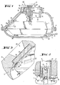
- a standard electronic precision balance 1 of the applicant is housed in a surrounding, pressure-resistant housing 3, 4, which consists of a cover part 3 and a base part 4, which have circumferential flanges which are firmly connected to one another with the aid of a plurality of screws 5 or other clamping means are.
- the scale 1 has, in a known manner, a large number of electronic components and a transformer which are fed from the outside via the electrical cable 32, the cable 32 being short-circuit-proof and fail-safe and inserted through the cable bushing 31 into the pressure-resistant housing 3, 4 .
- the weighing system of the scale 1 can work, for example, according to the principle of electromagnetic force compensation and ends with its load receiver 2 on the top of the scale 1 and normally picks up a load pan.
- the invention is shown on an upper-pan scale, but it is possible to use the same principle for a lower-pan scale.
- the parallel guide described below is arranged in the bottom part 4 of the pressure-resistant housing 3, 4.
- On the weighing system 2 is supported by balls 11 and ball pans 12, the linkage formed from the adapter 10 and plunger 9 for the actual weighing pan 6.
- the plunger 9 passes through the cover part 3 of the pressure-resistant housing without contact, an annular gap of approximately 25 mm in length and 0.2 mm in width being formed between the housing part 3 and the plunger 9.
- the plunger 9 is guided in parallel with the aid of an upper link 13 and a lower link 14, the upper link 13 and lower link 14 having articulated points 33 in a known manner, which in the area of the clamping point Ram 9 and in the area of the clamping points of the fixed points 16 of the cover part 3 are provided.
- the possible vertical movement of the load shell 6 and the plunger 9 is limited by stops 8 and is a few tenths of a millimeter.
- the upper link 13 is covered with a protective hood 7, which ends in the region of the plunger 9 in a collar 18 and forms a labyrinth seal with a further collar 18 'of the plunger 9, with which the penetration of foreign bodies into the weighing system is prevented.
- the plunger 9 also has a bracket 19 on which a dead load spring 17 engages, which on the other hand is fastened to a gallows 34 of the housing cover 3 and with the help of which the vertically movable parts such as plunger 9, parallel guide 13, 14 and weighing pan 6 in a position that does not stress the weighing system 2.
- the adjustment can be carried out at any time by means of the setting means located outside the pressure-resistant housing 3, 4, without the need for additional adjustment of the balance 1 located in the pressure-resistant housing 3, 4.
- a viewing window 23 is provided in the cover part 3, which is also designed to be pressure-resistant with the aid of a transparent pane 24 made of tempered glass.
- the bulletproof glass 24 is supported in a circumferential inner fold 25, a lead sealing frame 26 being provided as a seal and lining between the inner fold 25 and the bulletproof glass 24 and a lead frame 29 made of lead between the bulletproof glass 24 and a clamping frame 27.
- the bulletproof glass pane 24 is clamped in the inner fold 25 with the aid of screws 28 and the clamping frame 27.
- FIG. 2 shows a variant of the connection of the plunger 9, adapter 10 and weighing system 2 already shown in FIG. 1.
- the adapter 10 is mounted in a blind hole 21 which is open towards the weighing system 2 and is likewise articulated via balls 11 and ball sockets 12 coupled with the plunger 9 and the weighing system 2.
- the balance 1 is immovably fixed in the base part 4 with the aid of the supports 30, so that the pressure-resistant housing 3, 4 can also be transported safely with the internal balance 1 without the risk that the balance 1 within the pressure-resistant housing 3, 4 slips back and forth.
- the fixation is only possible within a certain tolerance dimension, a rigid connection between the plunger 9 and the weighing system 2 would damage the same or the parallel guide 13, 14.
- the adapter 10 Due to the articulated mounting and interposition of the adapter 10 with the help of the balls and ball pans, the adapter 10 has the possibility of pivoting slightly transversely to its vertical axis about the respective pivot point without this having any harmful effects on the weighing system 2.
- the blind hole 21 is accordingly kept somewhat larger in diameter than the diameter of the adapter 10. In the embodiment according to FIG. 1, the adapter 10 can migrate slightly to the side in the same way.
- the overall height of the pressure-resistant housing 3, 4 can be reduced in that the upper link 13 is arranged outside the cover part 3 and that, according to FIG. 2, the adapter 10 is included in a blind hole 21 of the plunger 9.
- the inner outline shape of the pressure-resistant housing 3, 4 is preferably matched to that of a hollow ball or an elongated depression in order to ensure a favorable pressure distribution.
- additional electronics can be housed explosion-proof z. B. coupling devices.
- Scales with higher loads are mostly designed as so-called weighbridges.
- a rectangular load pan is supported at the four corner points on a bridge of the weighing system (e.g. GB-PS 1 369 035).
- the parallel guide shown in FIGS. 1 and 2 can also be used for such weighbridges.
- the adapter 10 can either merge into a rigid distribution cross, the ends of which are supported on the bridge of the weighing system, or each corner point of the bridge is loaded by a separate plunger with parallel guidance. which is passed through the housing 3, 4 analogously to FIG. 1.
- the external load pan is adapted to the load pan of the weighbridge and is supported either via a distributor cross on the central plunger or at the four corner points on the four plungers with parallel guidance.
Landscapes
- Physics & Mathematics (AREA)
- General Physics & Mathematics (AREA)
- Measuring Fluid Pressure (AREA)
- Casings For Electric Apparatus (AREA)
- Arrangements For Transmission Of Measured Signals (AREA)
Claims (13)
Applications Claiming Priority (2)
| Application Number | Priority Date | Filing Date | Title |
|---|---|---|---|
| DE7913203U | 1979-05-08 | ||
| DE19797913203U DE7913203U1 (de) | 1979-05-08 | 1979-05-08 | Waage |
Publications (2)
| Publication Number | Publication Date |
|---|---|
| EP0018656A1 EP0018656A1 (fr) | 1980-11-12 |
| EP0018656B1 true EP0018656B1 (fr) | 1983-07-27 |
Family
ID=6703780
Family Applications (1)
| Application Number | Title | Priority Date | Filing Date |
|---|---|---|---|
| EP80102406A Expired EP0018656B1 (fr) | 1979-05-08 | 1980-05-03 | Balance utilisable dans des zônes à danger d'explosion |
Country Status (3)
| Country | Link |
|---|---|
| US (1) | US4320809A (fr) |
| EP (1) | EP0018656B1 (fr) |
| DE (2) | DE7913203U1 (fr) |
Cited By (1)
| Publication number | Priority date | Publication date | Assignee | Title |
|---|---|---|---|---|
| EP1576343B2 (fr) † | 2002-11-15 | 2018-07-11 | Mettler-Toledo GmbH | Module de pesee pourvu d'un dispositif de depoussierage |
Families Citing this family (18)
| Publication number | Priority date | Publication date | Assignee | Title |
|---|---|---|---|---|
| US4416343A (en) * | 1981-05-13 | 1983-11-22 | Sartorius Gmbh | Electromechanical weigher |
| JPS59145922A (ja) * | 1983-02-09 | 1984-08-21 | Shimadzu Corp | 電子天びん |
| US4492280A (en) * | 1983-02-28 | 1985-01-08 | Masstron Scale Inc. | Weighing apparatus including load cells with intrinsic safety barrier |
| GB2150307B (en) * | 1983-11-21 | 1988-09-01 | Kubota Ltd | Load cell having flameproof enclosure |
| DE3437959A1 (de) * | 1984-10-17 | 1986-04-17 | Sartorius GmbH, 3400 Göttingen | Elektronische waage zum einsatz in explosionsgefaehrdeten bereichen |
| NL8800278A (nl) * | 1988-02-05 | 1989-09-01 | Tec Keylard Weegschalen Nederl | Toonbank met geintegreerde elektronische weegschaal. |
| EP0362567B1 (fr) * | 1988-09-07 | 1992-12-09 | Ishida Scales Mfg. Co., Ltd. | Dispositif étanche pour le pesage automatique |
| JP2000241260A (ja) * | 1999-02-22 | 2000-09-08 | Japan Atom Energy Res Inst | 力・荷重測定器 |
| DE10025712C2 (de) * | 2000-05-25 | 2003-11-13 | Mettler Toledo Gmbh | Waage mit Überdruckgehäuse |
| DE10149606C2 (de) * | 2001-10-09 | 2003-12-24 | Mettler Toledo Gmbh | Labyrinthdichtung mit lösbarem Ringelement und Waage |
| US7002084B2 (en) * | 2002-01-16 | 2006-02-21 | Weightech, Inc. | Modular sealed portable digital electronic controller |
| US20080230282A1 (en) * | 2005-08-05 | 2008-09-25 | Weightech, Inc. | Modular sealed portable digital electronic controller |
| US7710714B2 (en) * | 2004-09-13 | 2010-05-04 | Bettcher Industries, Inc. | Housing for scale or load cell controller |
| EP1938058B1 (fr) * | 2005-10-12 | 2016-04-20 | Wipotec Wiege- und Positioniersysteme GmbH | Cellule de pesage avec support de reception |
| DE102005055754B4 (de) * | 2005-11-21 | 2016-10-20 | Wipotec Wiege- Und Positioniersysteme Gmbh | Aufnahme für das Antriebsaggregat einer Transportvorrichtung |
| USD548121S1 (en) | 2005-12-09 | 2007-08-07 | Bettcher Industries, Inc. | Housing for scale or load cell controller |
| US7554043B2 (en) * | 2007-05-03 | 2009-06-30 | Edlund Company, Inc. | Weighing scale having dual housings |
| DE202009005883U1 (de) * | 2009-01-23 | 2010-03-11 | Futehally, Habib | Förderbandwaage |
Family Cites Families (9)
| Publication number | Priority date | Publication date | Assignee | Title |
|---|---|---|---|---|
| US2661181A (en) * | 1951-10-31 | 1953-12-01 | Arthur J Stock | Air lock coal scale |
| FR1199877A (fr) * | 1957-07-16 | 1959-12-16 | Molins Machine Co Ltd | Dispositif de pesage perfectionné |
| DE1084046B (de) * | 1959-03-04 | 1960-06-23 | Schenck Gmbh Carl | Kraftmessdose |
| US3166136A (en) * | 1963-07-12 | 1965-01-19 | Raphael T Coffman | Apparatus for weighing material in a sealed enclosure |
| CH405742A (de) * | 1964-01-17 | 1966-01-15 | Mepag Ag | Waage mit gasdichtem Waagengehäuse |
| US3444943A (en) * | 1967-08-28 | 1969-05-20 | Hulbert T Tytus | Weighing system with sealed enclosure |
| DE2214418A1 (de) * | 1972-03-24 | 1973-10-11 | Hoefliger & Karg | Waegegeber |
| DE2460734A1 (de) * | 1974-12-21 | 1976-04-22 | Sauter August Gmbh | Waage mit einer aufnahmevorrichtung fuer den waegemechanismus |
| CH604143A5 (fr) * | 1976-12-14 | 1978-08-31 | Mettler Instrumente Ag |
-
1979
- 1979-05-08 DE DE19797913203U patent/DE7913203U1/de not_active Expired
-
1980
- 1980-05-02 US US06/146,185 patent/US4320809A/en not_active Expired - Lifetime
- 1980-05-03 DE DE8080102406T patent/DE3064378D1/de not_active Expired
- 1980-05-03 EP EP80102406A patent/EP0018656B1/fr not_active Expired
Cited By (1)
| Publication number | Priority date | Publication date | Assignee | Title |
|---|---|---|---|---|
| EP1576343B2 (fr) † | 2002-11-15 | 2018-07-11 | Mettler-Toledo GmbH | Module de pesee pourvu d'un dispositif de depoussierage |
Also Published As
| Publication number | Publication date |
|---|---|
| US4320809A (en) | 1982-03-23 |
| EP0018656A1 (fr) | 1980-11-12 |
| DE3064378D1 (en) | 1983-09-01 |
| DE7913203U1 (de) | 1980-05-14 |
Similar Documents
| Publication | Publication Date | Title |
|---|---|---|
| EP0018656B1 (fr) | Balance utilisable dans des zônes à danger d'explosion | |
| DE10054847C2 (de) | Wägeaufnehmer mit Justiergewicht | |
| EP2278285B1 (fr) | Capteur de charge pouvant être relié | |
| AT513918B1 (de) | Einstellsystem für einen Fahrzeug-Scheinwerfer sowie Fahrzeug-Scheinwerfer | |
| EP3153830A1 (fr) | Support de charge ayant un dispositif de verrouillage | |
| EP3380814A1 (fr) | Boîtier protégé contre les explosions pour moyens d'émission et de réception de rayonnement électromagnétique | |
| CH657918A5 (de) | Elektromechanische waage. | |
| DE10025712C2 (de) | Waage mit Überdruckgehäuse | |
| DE102018106617A1 (de) | Kalibriergewicht und Kalibrieradapter | |
| DE1164125B (de) | Optische Einrichtung zum Pruefen von Glaserzeugnissen | |
| DE3208015A1 (de) | Elektromechanische waage | |
| DE2527883A1 (de) | Wiegevorrichtung | |
| EP0077981B1 (fr) | Dispositif pour le contrôle de la densité d'un gaz électronégatif dans le blindage d'une installation de distribution électrique | |
| DE3144260C2 (fr) | ||
| CH656233A5 (de) | Justiervorrichtung fuer ein in einem traeger angeordnetes optisches element einer optischen anordnung. | |
| DE4136717C2 (de) | Einrichtung zum Dosieren und Wägen von schüttfähigen Materialien | |
| DE2107219C3 (de) | Mehrteiliges Gehäuse zur schlagwettersicheren Kapselung bzw. explosionsgeschützten Unterbringung eines optischen Gerätes | |
| EP0921379B1 (fr) | Dispositif de pesage pour carrosseries de véhicules avec cellule de charge mobile | |
| DE3242156A1 (de) | Waagschale mit integrierter ueberlastsicherung | |
| DE693607C (de) | Einrichtung zur Mittenfuehrung von Schmelzleitertraegern in Hochspannungssicherungsrohren | |
| DE2114449B2 (de) | Lasergeraet fuer den einsatz in schlagwetter- oder explosionsgefaehrdeten betrieben | |
| DE726921C (de) | OElausdehnungsgefaess, das gegenueber der Aussenluft vollkommen dicht abgeschlossen ist, insbesondere fuer elektrische Kondensatoren | |
| DE3416528A1 (de) | Vorrichtung zur gewichtsmessung von gegenstaenden sowie festen oder fluessigen stoffen | |
| DE1099758B (de) | Anordnung zur Messung der Temperatur an rotierenden Koerpern | |
| DE2456688A1 (de) | Stabile plattformkonstruktion fuer laseroptiken |
Legal Events
| Date | Code | Title | Description |
|---|---|---|---|
| PUAI | Public reference made under article 153(3) epc to a published international application that has entered the european phase |
Free format text: ORIGINAL CODE: 0009012 |
|
| AK | Designated contracting states |
Designated state(s): CH DE FR GB |
|
| 17P | Request for examination filed |
Effective date: 19810429 |
|
| GRAA | (expected) grant |
Free format text: ORIGINAL CODE: 0009210 |
|
| AK | Designated contracting states |
Designated state(s): CH DE FR GB LI |
|
| REF | Corresponds to: |
Ref document number: 3064378 Country of ref document: DE Date of ref document: 19830901 |
|
| ET | Fr: translation filed | ||
| PLBE | No opposition filed within time limit |
Free format text: ORIGINAL CODE: 0009261 |
|
| STAA | Information on the status of an ep patent application or granted ep patent |
Free format text: STATUS: NO OPPOSITION FILED WITHIN TIME LIMIT |
|
| 26N | No opposition filed | ||
| PGFP | Annual fee paid to national office [announced via postgrant information from national office to epo] |
Ref country code: DE Payment date: 19910430 Year of fee payment: 12 |
|
| PGFP | Annual fee paid to national office [announced via postgrant information from national office to epo] |
Ref country code: CH Payment date: 19920416 Year of fee payment: 13 |
|
| PGFP | Annual fee paid to national office [announced via postgrant information from national office to epo] |
Ref country code: FR Payment date: 19920429 Year of fee payment: 13 |
|
| PGFP | Annual fee paid to national office [announced via postgrant information from national office to epo] |
Ref country code: GB Payment date: 19920501 Year of fee payment: 13 |
|
| PG25 | Lapsed in a contracting state [announced via postgrant information from national office to epo] |
Ref country code: DE Effective date: 19930202 |
|
| PG25 | Lapsed in a contracting state [announced via postgrant information from national office to epo] |
Ref country code: GB Effective date: 19930503 |
|
| PG25 | Lapsed in a contracting state [announced via postgrant information from national office to epo] |
Ref country code: LI Effective date: 19930531 Ref country code: CH Effective date: 19930531 |
|
| GBPC | Gb: european patent ceased through non-payment of renewal fee |
Effective date: 19930503 |
|
| PG25 | Lapsed in a contracting state [announced via postgrant information from national office to epo] |
Ref country code: FR Effective date: 19940131 |
|
| REG | Reference to a national code |
Ref country code: CH Ref legal event code: PL |
|
| REG | Reference to a national code |
Ref country code: FR Ref legal event code: ST |