EP0018932A1 - Drahtseilbahn-Transportvorrichtung mit doppeltem Umlaufseil und veränderlicher Geschwindigkeit - Google Patents
Drahtseilbahn-Transportvorrichtung mit doppeltem Umlaufseil und veränderlicher Geschwindigkeit Download PDFInfo
- Publication number
- EP0018932A1 EP0018932A1 EP80420055A EP80420055A EP0018932A1 EP 0018932 A1 EP0018932 A1 EP 0018932A1 EP 80420055 A EP80420055 A EP 80420055A EP 80420055 A EP80420055 A EP 80420055A EP 0018932 A1 EP0018932 A1 EP 0018932A1
- Authority
- EP
- European Patent Office
- Prior art keywords
- cable
- transport device
- link
- speed
- mobile
- Prior art date
- Legal status (The legal status is an assumption and is not a legal conclusion. Google has not performed a legal analysis and makes no representation as to the accuracy of the status listed.)
- Granted
Links
Images




Classifications
-
- B—PERFORMING OPERATIONS; TRANSPORTING
- B61—RAILWAYS
- B61B—RAILWAY SYSTEMS; EQUIPMENT THEREFOR NOT OTHERWISE PROVIDED FOR
- B61B9/00—Tramway or funicular systems with rigid track and cable traction
-
- B—PERFORMING OPERATIONS; TRANSPORTING
- B61—RAILWAYS
- B61B—RAILWAY SYSTEMS; EQUIPMENT THEREFOR NOT OTHERWISE PROVIDED FOR
- B61B12/00—Component parts, details or accessories not provided for in groups B61B7/00 - B61B11/00
- B61B12/10—Cable traction drives
- B61B12/105—Acceleration devices or deceleration devices other than braking devices
-
- B—PERFORMING OPERATIONS; TRANSPORTING
- B61—RAILWAYS
- B61B—RAILWAY SYSTEMS; EQUIPMENT THEREFOR NOT OTHERWISE PROVIDED FOR
- B61B12/00—Component parts, details or accessories not provided for in groups B61B7/00 - B61B11/00
- B61B12/12—Cable grippers; Haulage clips
- B61B12/122—Cable grippers; Haulage clips for aerial ropeways
-
- B—PERFORMING OPERATIONS; TRANSPORTING
- B61—RAILWAYS
- B61B—RAILWAY SYSTEMS; EQUIPMENT THEREFOR NOT OTHERWISE PROVIDED FOR
- B61B15/00—Combinations of railway systems
-
- B—PERFORMING OPERATIONS; TRANSPORTING
- B65—CONVEYING; PACKING; STORING; HANDLING THIN OR FILAMENTARY MATERIAL
- B65G—TRANSPORT OR STORAGE DEVICES, e.g. CONVEYORS FOR LOADING OR TIPPING, SHOP CONVEYOR SYSTEMS OR PNEUMATIC TUBE CONVEYORS
- B65G23/00—Driving gear for endless conveyors; Belt- or chain-tensioning arrangements
- B65G23/38—Driving gear for endless conveyors; Belt- or chain-tensioning arrangements for effecting intermittent movement of belts or chains
Definitions
- the present invention relates to a closed circuit transport device, with variable speed, and offering the advantages of a kinematic chain system of the funicular type.
- the movable member leaves a motor device programmed in a given way to join with another motor device programmed differently from the previous one: for example, the mobile leaves the cable which performs the kinematics of the funicular to hang onto a slower cable or to slow down on its own.
- this type of system has kinematics for the line and (different) kinematics for the station.
- the present invention aims to overcome all the above drawbacks by providing a device which retains the advantages of the cinematics to the funicular.
- Another object of the invention is to provide regulation means capable of always maintaining the voltage of the variator cable below a predetermined limit value, in low speed zones.
- a transport device comprises a track or circuit closed in on itself, or at least one mobile assembly, to constitute a mode of transport of the funicular type, and it is characterized in that the mobile is always secured to a first link which carries out the variation in the speed of movement of the mobile along the circuit, while this mobile is connected integrally and intermittently to a second circulating link, according to a looped track, at a constant high speed, to pull the mobile or a series of mobile all permanently attached to the first link.
- the speed variator link is constituted by a device forming a chain of links of variable length which determines the distance between two successive mobiles, thus making it possible to maintain the "pitch" of the mobiles of the system, while this chain transmits only the tension necessary to tow the mobiles in the variable speed zone, this chain no longer being driving.
- the second link or link engine-tractor circulates at constant speed equal to the highest speed of the mobile or of the system of the invention.
- This tractor link practically collects the traction, braking and other mechanical forces, while its scrolling in a looped circuit at high speed limits tensions.
- This link is, for example, a cable or a series of tractor cables each looped on itself, this or these cables leaving free the speed variation zone or zones in which the mobiles are detached from the tractor link, which lightens the system.
- the system comprises a regulation device in each speed variation zone, this device being common to all the towing cables and having the aim of prohibiting the crossing of a predetermined threshold for the tension in the variator link, by controlling the driving organs of the tractor links.
- the security and reliability of the system are maximum, the mobiles never being free, while the variations in speed (entry and exit in station) are obtained by interaction between elements of a mobile and ramps of the fixed structure of the system, so that the auxiliary safety devices can be considerably simplified.
- the voltage is regulated by a device detecting the force collected by the fixed ramp during the speed variation, therefore of the voltage variation in the variator link.
- connection between a mobile and a tractor link is produced either by pliers, or similar friction device, or by control of parts integral with the tractor link.
- the means ensuring the regulation of the voltage in the variator link act, for a given station, within the sole framework of this station, without acting, by any mode whatsoever, on the motors d drive of the towing cables, and at their own speed, the term "station" designating the area traversed by a mobile between the moment when it has just released the towing cable and the moment when it is re-solidified from the towing cable.
- said regulation means are means capable of varying in a controlled manner the position of the point where the mobile is resolidated from the towing cable.
- a servo device for controlling said means for varying the position of the connection point as a function of the voltage in the variator link detected at the station in question.
- the servo device is provided for adjusting the position of this control ramp as a function of the delay of the mobiles leaving the station.
- the assembly is provided so that the normal gripping of the tractor cable by the clamp of each mobile takes place at a location fixed by construction before the end of the ramps controlling the unwinding, the effective location for gripping the tractor cable by the clamps being able to move on either side of the normal location.
- said regulation means are means capable of inducing a variation of the speed law in the station considered.
- the means capable of inducing a variation in the speed law act on the position of the ramps which limit the length of unwound cable.
- an elastic member is interposed on the section of variator cable which separates two consecutive mobiles.
- each elastic member is associated with a ratchet system which allows the movement of said member only in the deceleration zone and in the low speed zone of the stations.
- each mobile - comprises two connecting members with the towing cable, namely: a first connecting member which secures said mobile to the towing cable in high-speed areas, and a second connecting member capable of carrying out friction training with sliding of varying degrees.
- the second connecting member comprises, for each mobile, a pair of clamping pulleys pinching the towing cable between them, each clamping pulley being composed of two complementary half-pulleys mounted to rotate on a same shaft secured to the mobile, where these two half-pulleys are stacked with friction discs, while means make it possible to tighten more or less the stack of each shaft depending on the overvoltage in the variator link.
- security systems are provided so that a mobile which decelerates always pulls on its rear cable, or upstream, but never on its front cable, or downstream, beyond a certain traction force of predetermined value, while on the contrary a mobile which accelerates always pulls on its front cable, but never on its rear cable beyond a certain traction force of predetermined value.
- each deceleration zone is on a downward slope.
- the safety systems consist of an increase in the inertia of the mobiles, by simple increase in their mass, or by means of flywheels linked in rotation to the rolling members.
- the security systems consist of systems capable of exerting on the decelerating mobiles a thrust oriented in the direction of movement, this thrust being sufficient to balance at least all the accidental and random causes of braking likely to occur.
- said systems consist of linear electric motors of the type where the windings are housed in the fixed part and where the unwound armature is housed in the mobile.
- FIG. 1 a mode of transport using kinematics to funicular.
- a link chain of variable length 1 is looped on itself.
- Each link carries a mobile 2 which remains permanently attached to the chain.
- the transport system is completed by a tractor link, for example a cable 3, looped around itself and driven at high constant speed (equal to the highest speed of mobiles 2) by a motor device 4 of any known type. .
- FIG. 1 While the funicular in FIG. 1 has only one zone DA for high-speed scrolling and a single station zone comprising the section AB of deceleration, the section BC of low speed (or stopped and the CD acceleration section, FIG. 2 illustrates a circuit whose variation chain 1 cooperates with several tractor link sections 5, 6, 7, each section being looped back on itself. tractor links leave free, between them, the intervals corresponding to the speed variations of the mobiles at stations 9, 10, 11.
- the towing cables only extend in high-speed areas: the mobiles are then secured to both the variator and tractor links. On the contrary, in station areas (speed variation), the mobiles are detached from the tractor link, as illustrated in FIGS. 3 to 5 and 10, while they remain fixed to the chain or variator link.
- the engine force is applied simultaneously to each of the mobiles 2 located in the high-speed zones.
- This tensile force is provided by the tractor cable and no longer by the chain 1.
- the connecting members between the links of variable length can thus be standardized. In particular, they no longer have to be adapted to the length of the closed circuit, or to be calculated for voltages at low speed.
- FIG 3 shows a portion of a transport system whose successive mobile lss are constituted by bogies Bi, Bi +1 ⁇ while the upstream bogie Bi is connected to the previous downstream bogie Bi +1 by a variator cable 8 or variator link, which is wound on the downstream and upstream coils respectively of the upstream and downstream bogies.
- each reel comprises a device for controlling rotation, constituted by a roller-bearing plate 12 and 12a capable of coming into abutment against ramps 13 secured to the fixed structure of the system of the invention, and arranged in the areas of speed variation.
- each Bi bogie is fitted with a Pi clamp for its intermittent friction connection with the towing cable 3.
- the Bi mobile travels at constant high speed. It is secured by its clamp Pi, the cable 3 which runs at constant high speed.
- the bogie or downstream mobile B i + 1 has entered the slowdown zone. Its clamp P i + 1 opened under the effect of a control mechanism of any type known, not shown smelled, and placed in the entrance portion of the station ( Figure 6).
- the bogie B i + 1 is detached from the tractor cable 3, but remains integral with the funicular assembly formed subsequently by the bogies, by the variator cable 8.
- the coil b i + 1.1 is rotated in the direction of the arrow 18, by the action of the ramps 13 on the rollers 12 and 12a.
- the coil winds the variator cable 8 on itself and the length of the link M, defined by the distance between the clamps Pi and P i + 1 decreases.
- FIGS. 4 and 5 Another construction of a system according to the invention is illustrated in FIGS. 4 (median side view) and 5 (top view).
- the tractor link 3 runs at high constant speed, from left to right. It carries, at regular intervals, a means for the articulation of a pair of cleats t i, 1 and ti, 2, provided with rollers 19 for rolling or sliding on the ramps 20 of the fixed structure of the transport device, and bearing surfaces 21 to constitute the positive connection members between the tractor cable and a chain with deformable links.
- the mobiles of the system are cross members T i which carry, in known manner, idler rollers for cables or ribbons 22, closed on themselves, each of constant length, as well as means of support on lateral ramps 23 arranged in the speed variation zones.
- a chain with deformable links Mi is produced (FIG. 5).
- FIGS 4 and 5 show a slowdown zone.
- the sleepers T i-1 and T i circulate at high constant speed, along arrow 15A. They are secured, by the cleats t i-1 , and titi of the tractor cable 3 which runs at constant speed.
- the cross member T i + 1 has entered the deceleration phase: the cleats t i + 1 are open. The cross is disconnected from the cable 3. Its two opposite yokes deviate from one another under the action of the ramps 23 against which come to abut and roll rollers 24.
- the mobile Ti +1 remains integral with the assembly funicular of the series of crosspieces by the ribbon 22 which forms a link with constant perimeter.
- the link M i + 1 deforms in s' widening, therefore shortening, hence a slowing down of the mobile T i + 1 .
- this regulation system is to limit the voltage in the dimmer cable.
- the value of this voltage is detected by means of the device illustrated in FIG. 8.
- the bogie B i in the station zone, or low speed zone (corresponding to the section BC of FIG. 6) is connected to the bogie which follows it and to the bogie which precedes it by the variator link 8, which is wound on coils b i integral in rotation with rollers 12 and 12a bearing against the ramp 13a which is part of the fixed structure of the system.
- the tension exerted on the link 8 introduces a torque into the coil b i , a torque which is collected by the support of the roller 12 on the ramp 13a.
- the voltage in the variator link (cable) 8 will be detected, recorded and regulated by the measurement of the force exerted on the ramp 13a, measurement carried out by a known device represented at 33, for example a sensor-detector.
- a known device represented at 33, for example a sensor-detector.
- the regulation system gives the order to the drive member 25 of the tractor link 5, at the entrance of the deceleration zone AB (FIG. 6) , accelerate for a given time, or perform an additional rotation to bring the voltage back within desired limits.
- tractor link loops in the device of the invention will avoid any excess voltage on the variator link, both when the system is launched and during normal operation, braking or emergency stop.
- FIGS. 9 and 10 Another preferred construction variant has been illustrated in FIGS. 9 and 10: the station zone (s) are provided at the ends of the loop formed by the towing cable. It can be seen that the variation chain 1 follows, in the end zones E, a path E 1 E 2 which deviates appreciably from that of the tractor cable 3 returned by the drive wheel 4. This construction is close to that of the Figure 1, with the difference that the station areas are located at the ends of the system channel.
- the tractor cable leaves free the end zone E which is the speed variation zone of the mobiles 2 secured to the variator link 1.
- the mobiles are each equipped with a device for clamp 40 intended to make their intermittent connection with the tractor cable (fig 10). If we consider that the direction of movement of the mobiles is that indicated by the arrows 41, the clamps are ordered to open when the mobiles arrive at the start of the section R 1 R 2 of connection on the variator link.
- the mobile is then separated from the tractor cable, and follows the path of the variator link, passing through a deceleration zone, a station or low speed zone and an acceleration zone (in FIG. 9, these zones have been referenced respectively by the letters D, PV, A). Finally, the mobile reaches the second connection section R ' 1 R' 2 where its clamp is ordered to close on the tractor cable.
- the mobile (2) can then enter the high-speed area GV along which it is integral with the two variator and tractor cables (fig 9 and 10).
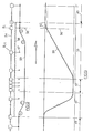
- STATION designates the zone traversed by a mobile secured to a bogie B between the moment when this bogie has just released the tractor cable 50 and the moment where it resociates itself from this towing cable. Between these two moments, the bogie considered will have successively traversed a zone 51 of deceleration, a zone 52 of low speed, and a zone 53 of acceleration. On either side of the station, there are of course high speed zones 49. In parallel with the routing of the tractor cable 50 and the variator cable 54, a speed diagram 55 has been drawn.
- FIG. 12 A first example of such a regulation device is illustrated in FIG. 12, placed in correspondence with the speed diagram of FIG. 13.
- regulation means capable of causing the position to move upstream are used. from point 56 where the bogie is resolidated from the tractor cable 50. We thus see the bogie Bi grab the tractor cable 50 by its clamp 57 before the end of the acceleration zone 53 where the ramps 58 unwind the variator cable 54.
- the curve 59 of the speed diagram corresponds to the variation of the speeds obtained using only the ramps 58.
- the speed variation is then in accordance with the new layout 60.
- this new layout corresponds to a faster acceleration than that of curve 59, the ramps 58 continuing to unwind a certain length of variator cable 54 after the instant corresponding to point 56, slack is obtained in the section of the variator cable separating the bogie B i of the bogie B i + 1 which immediately precedes it. This slack arises to the detriment of the slack present in the variator cable at the station considered.
- this operation makes it possible to re-tension the variator cable 54 at this station.
- any known means can be used.
- a simple combination of known means allows in this way to achieve the desired regulation: detecting the delay d * a bogie comes out of the station set back the control ramp for holding the open clip. The more the delay increases, the more this control ramp moves back. The more the bogie grips the tractor cable 50 t8t, the more the variator cable 54 is tensioned in the station concerned.
- the regulation means are constituted by an elastic system such as a spring 62 interposed on the section of the variator cable 54 which separates two consecutive bogies.
- a predetermined stress is preferably given to the spring.
- the system can be improved by associating each spring 62 with two non-return pawls 63 capable of engaging on racks 64.
- the pawls When the pawls are delivered to the action of the single spring 62, their respective active ends remain engaged on the racks 64 to lock the mechanism and prevent any movement of the spring 62.
- the free ends of the pawls 63 are supported on opening ramps 64, these pawls are driven at a distance from the racks 64, so that the mechanism is to be unlocked to allow free movement of the spring.
- opening ramps 64 are provided in the low speed zone of each station, but are absent in the re-acceleration zone.
- the pawls 63 thus preventing the spring 62 from returning to its natural position when, during the re-acceleration, the tension of the variator cable 54 decreases in opposite direction to the speed. This process amounts to slackening the variator cable 54 in the station considered.
- Ramps are provided at the entrance to each station to cause the pawls 63 to jump when passing through the deceleration zone. The slack that is given to the variator cable 54 in a given station is automatically compensated for by an increase in the tension of this same cable in the next station.
- the regulation device which has just been described is less advantageous than those which have been described previously: the correction of length is not fast considering that the variation obtained is divided by the ratio of extreme speeds.
- This device is, on the other hand, advantageous when it is no longer a weak drift repeatedly repeated, but a brutal excess which caused a delay detrimental to a bogie or a small number of bogies.
- a foreign body introduces at the entrance of the station, on a bogie, a delay of L meters.
- R represents the ratio between the high speed V of the high speed zones 49 and the low speed v of the low speed zone 52.
- the delay of L meters of the bogie still in the zone close to the high speed zone goes immediately result in an elongation equal to elastic systems located at this moment in the low speed zone 52.
- the only overvoltage of the variator cable 54 which will result therefrom will be the overvoltage corresponding to the over-compression of the elastic systems for the elongation equal to , and the excess voltage will be easily swallowed.
- the problem of overvoltages in the variator cable 54 can also be resolved no longer by playing on local variations in the length of this cable, but by locally relieving this variator cable by means of a driving force taken directly from the tractor cable, via a friction mechanism.
- This type of solution is advantageous, for example, if a mechanical accident such as a seizing of rolling or that an introduction of foreign body in the mechanisms exerts a permanent braking on a given bogie.
- the braking intensity is increased when the bogie initiates a deceleration at the start of the station, and when this bogie reaches the low speed zone, the overvoltage of the variator cable 54 will thus have been multiplied by the ratio R of the speeds large and small areas se.
- each bogie is provided with two connecting members with the towing cable.
- the first connecting member is that which secures said bogie of the tractor cable in high-speed areas, and we know that it can, for example, a clamp.
- the second connecting member is capable of providing friction drive with sliding of varying degrees. The intensity of the friction must be able to be adjusted according to the overvoltage to be compensated, so that the compensation takes place by an additional driving force supplied by the towing cable.
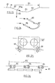
- the term "friction" is used here in its broadest sense: in the case of the example illustrated in FIGS. 17 to 19, there is for example a system which clamps the tractor cable between two pulleys 65 with a variable tightening intensity , or a gradual braking of the pulleys on a drive shaft 66.
- each pulley 65 comprises two substantially identical complementary half-pulleys 65a and 65b and mounted to rotate on the same transmission shaft 66 secured to the bogie Bi considered.
- This shaft 66 is immobilized in rotation in the bogie Bi, and a spring acting on the upper end of the shaft 66 constantly tends to pinch between the lower head 67 of the shaft 66 and a bearing 68 a stack comprising the half pulleys 65a and 65b and friction discs 69.
- This spring 70 is adjacent to a yoke 71 carrying a roller 72 capable of bearing on ramps 73.
- a servo device 74 in connection with a mechanism for positioning the ramps 73 and force sensors 75 positions the ramps 73 so as to more or less combat the pinching force supplied by the spring 70.
- the flanges of the pulleys 65 preferably carry tooth teeth 76 on their periphery. A meshing of these teeth ensures a balancing of the friction forces transmitted through the two pulleys.
- the voltage regulating means of the variator link according to the invention make it possible, on the one hand, to spare the variator cable by preventing this cable from being subjected to excessively high local voltages, and on the other hand, to avoid jolts training. mobiles, in particular when each mobile becomes detached from the towing cable.
- the invention provides a protection system, the operating principle of which can be stated in the following manner: it is made so that a mobile in deceleration always pulls on its rear cable, or upstream, but never on its front cable, or downstream, beyond a certain predetermined traction limit, while on the contrary a mobile in deceleration always pulls on its front cable, or downstream, but never on its rear cable, or upstream, beyond a certain predetermined traction limit.
- FIG. 23 shows a portion of a circuit comprising a high-speed zone 81, a deceleration zone 82, a low-speed zone 83, and an acceleration zone 84, the zones 82, 83 and 84 constituting a station 85.
- the deceleration zone 82 has been designed in a downward slope
- the acceleration zone 84 has been designed in an upward slope.
- the component of the gravity force 86 obtained by projection of this force on the running surface is indeed a force 86a directed so as to generate a traction of the mobile on its rear cable, this traction relieving all the tension of the front cable. Without the presence of the slope, we know that the tension of the front cable would have been multiplied in the low speed zone.
- Figure 24 shows the same principle of construction, but at the end of a looped circuit.
- the station 87 is arranged on an inclined terrain which gives the deceleration zone 88 a descending slope and the acceleration zone 89 an ascending slope.
- the inertia of the mobiles 90 can be increased either by directly increasing their mass, or indirectly by providing each mobile with at least one flywheel linked in rotation with the rolling members 91 of this mobile.
- a linear motor 93 of the type according to which the coils 94 are housed in the fixed part is then provided along the deceleration zones 92, or on part of these zones. that the armature not wound is housed in the mobile 95.
Landscapes
- Engineering & Computer Science (AREA)
- Mechanical Engineering (AREA)
- Transportation (AREA)
- Transmissions By Endless Flexible Members (AREA)
- Tension Adjustment In Filamentary Materials (AREA)
- Control Of Conveyors (AREA)
Applications Claiming Priority (7)
| Application Number | Priority Date | Filing Date | Title |
|---|---|---|---|
| FR7912141 | 1979-05-08 | ||
| FR7912141A FR2456024A1 (fr) | 1979-05-08 | 1979-05-08 | Dispositif de transport funiculaire, a double cable, boucle sur lui-meme et a variation de vitesse |
| FR8001157A FR2473442A2 (fr) | 1980-01-16 | 1980-01-16 | Dispositif de transport funiculaire, a double cable, boucle sur lui-meme et a variation de vitesse |
| FR8001157 | 1980-01-16 | ||
| FR8010659A FR2484349A2 (fr) | 1980-05-07 | 1980-05-07 | Dispositif de transport funiculaire, a double cable, boucle sur lui-meme et a variation de vitesse |
| FR8010659 | 1980-05-07 | ||
| US06/327,333 US4508205A (en) | 1979-05-08 | 1981-12-04 | Double cable funicular transport device, looped on itself and with speed variation |
Publications (2)
| Publication Number | Publication Date |
|---|---|
| EP0018932A1 true EP0018932A1 (de) | 1980-11-12 |
| EP0018932B1 EP0018932B1 (de) | 1984-03-28 |
Family
ID=27446396
Family Applications (1)
| Application Number | Title | Priority Date | Filing Date |
|---|---|---|---|
| EP80420055A Expired EP0018932B1 (de) | 1979-05-08 | 1980-05-08 | Drahtseilbahn-Transportvorrichtung mit doppeltem Umlaufseil und veränderlicher Geschwindigkeit |
Country Status (2)
| Country | Link |
|---|---|
| US (1) | US4508205A (de) |
| EP (1) | EP0018932B1 (de) |
Cited By (6)
| Publication number | Priority date | Publication date | Assignee | Title |
|---|---|---|---|---|
| WO1981002275A1 (fr) * | 1980-02-11 | 1981-08-20 | Kermadec J Huon | Systeme de transport automatique a vehicules passifs tractes par cable |
| EP0108202A1 (de) * | 1982-08-17 | 1984-05-16 | Axel De Broqueville | Transportsystem mit einem ausziehbaren Wagenzug und ausziehbaren Bandförderern |
| EP0306771A1 (de) * | 1987-09-09 | 1989-03-15 | Von Roll Transportsysteme AG | Gleiseinrichtung für die Fahrzeuge einer Förderanlage, insbesondere Umlauf-Seilförderanlage |
| FR2636028A1 (fr) * | 1988-09-07 | 1990-03-09 | Brissonneau & Lotz | Perfectionnement au dispositif de transport funiculaire a double cable |
| FR2691692A1 (fr) * | 1992-06-01 | 1993-12-03 | Soule Sa | Système de transport comprenant des véhicules roulant sur des rails et tractés par un câble. |
| CN113387137A (zh) * | 2021-06-29 | 2021-09-14 | 上海楼哒物流技术中心 | 一种钢丝绳的牵引方法、牵引装置和物流传输系统 |
Families Citing this family (13)
| Publication number | Priority date | Publication date | Assignee | Title |
|---|---|---|---|---|
| DE3406519A1 (de) * | 1984-02-23 | 1985-08-29 | Bergwerksverband Gmbh, 4300 Essen | Spannvorrichtung fuer kettengetriebene betriebsmittel |
| US4744306A (en) * | 1985-04-12 | 1988-05-17 | Kunczynski Jan K | Conveyor system and method of operation for an aerial tramway or the like |
| FR2605574B1 (fr) * | 1986-10-23 | 1990-06-08 | Creissels Denis Sa | Installation de transport ayant un cable aerien a defilement continu et des systemes lanceur et ralentisseur |
| DE3804168A1 (de) * | 1988-02-11 | 1989-08-24 | Gewerk Eisenhuette Westfalia | Planetenueberlagerungsgetriebe und ueberlagerungsantrieb fuer kettenbaender u. dgl., insbesondere fuer kettenfoerderer und kettengezogene bergbau-gewinnungsmaschinen |
| FR2641510B1 (fr) * | 1989-01-09 | 1991-03-29 | Von Roll Transportsysteme | Installation de transport par cable a tension controlee |
| US4953685A (en) * | 1989-08-10 | 1990-09-04 | Otis Elevator Company | Step chain for curved escalator |
| US6766898B2 (en) * | 2001-09-07 | 2004-07-27 | Claude Lessard | Surface conveyor with variable delivery rate for bagging bakery products |
| KR100617419B1 (ko) * | 2003-12-19 | 2006-08-30 | 오티스 엘리베이터 컴파니 | 저소음 체인이상감지장치 |
| FR2881923A1 (fr) * | 2005-02-15 | 2006-08-18 | Mecatherm Sa | Sole pour four |
| JP5218097B2 (ja) * | 2009-01-27 | 2013-06-26 | 千住金属工業株式会社 | 自動はんだ付け装置及び搬送装置 |
| RU2530202C2 (ru) * | 2009-06-16 | 2014-10-10 | Отис Элевэйтор Компани | Двухсоленоидный тормоз главного приводного вала эскалатора |
| US8812152B1 (en) * | 2013-02-22 | 2014-08-19 | TamiCare, Ltd. | Method and apparatus for changing carriage speed on a closed-loop track |
| GB2595666B (en) * | 2020-06-01 | 2022-10-05 | Fraser Monteiro Andre | Ropeway Transport System |
Citations (9)
| Publication number | Priority date | Publication date | Assignee | Title |
|---|---|---|---|---|
| US1886050A (en) * | 1930-03-14 | 1932-11-01 | Firm Adolf Bleichert & Co A G | Process for the working of passenger ropeways with continuous traffic |
| FR2190690A1 (de) * | 1972-06-30 | 1974-02-01 | Patin Pierre | |
| FR2202828A1 (de) * | 1972-10-13 | 1974-05-10 | Patin Pierre | |
| FR2207050A1 (de) * | 1972-11-17 | 1974-06-14 | Goodyear Tire & Rubber | |
| FR2236706A1 (en) * | 1973-07-02 | 1975-02-07 | Branchu Paul | Continuous motion transport system - has power driven endless chain to which vehicles are attached and detached |
| FR2272923A1 (de) * | 1974-02-25 | 1975-12-26 | Goodyear Tire & Rubber | |
| FR2302896A1 (fr) * | 1975-03-01 | 1976-10-01 | Gewerk Eisenhuette Westfalia | Station motrice de transporteur aerien avec dispositif de mise en tension du cable |
| FR2327899A1 (fr) * | 1975-10-17 | 1977-05-13 | Automatisme & Technique | Systeme de transport continu sur voie ferree |
| FR2345329A1 (fr) * | 1976-03-22 | 1977-10-21 | Savec | Convoyeur en boucle a vehicules relies elastiquement |
Family Cites Families (6)
| Publication number | Priority date | Publication date | Assignee | Title |
|---|---|---|---|---|
| US1903488A (en) * | 1931-12-28 | 1933-04-11 | Stibbs Harry | Conveyer system |
| US2609086A (en) * | 1949-05-26 | 1952-09-02 | Palmer Bee Co | Caterpillar drive chain |
| DE1812294A1 (de) * | 1967-12-06 | 1969-07-03 | Pirelli | Personenfoerderer |
| US3565238A (en) * | 1968-05-06 | 1971-02-23 | Basil J Candela | Variable-velocity conveyor |
| FR2236391A5 (de) * | 1973-07-02 | 1975-01-31 | Stephanois Rech Meca Hydr Cent | |
| FR2443955A1 (fr) * | 1978-12-13 | 1980-07-11 | Cesbron Lavau Rene | Dispositif de dilatation-contraction associe a un ensemble lineaire en defilement, et application aux trottoirs roulants |
-
1980
- 1980-05-08 EP EP80420055A patent/EP0018932B1/de not_active Expired
-
1981
- 1981-12-04 US US06/327,333 patent/US4508205A/en not_active Expired - Fee Related
Patent Citations (9)
| Publication number | Priority date | Publication date | Assignee | Title |
|---|---|---|---|---|
| US1886050A (en) * | 1930-03-14 | 1932-11-01 | Firm Adolf Bleichert & Co A G | Process for the working of passenger ropeways with continuous traffic |
| FR2190690A1 (de) * | 1972-06-30 | 1974-02-01 | Patin Pierre | |
| FR2202828A1 (de) * | 1972-10-13 | 1974-05-10 | Patin Pierre | |
| FR2207050A1 (de) * | 1972-11-17 | 1974-06-14 | Goodyear Tire & Rubber | |
| FR2236706A1 (en) * | 1973-07-02 | 1975-02-07 | Branchu Paul | Continuous motion transport system - has power driven endless chain to which vehicles are attached and detached |
| FR2272923A1 (de) * | 1974-02-25 | 1975-12-26 | Goodyear Tire & Rubber | |
| FR2302896A1 (fr) * | 1975-03-01 | 1976-10-01 | Gewerk Eisenhuette Westfalia | Station motrice de transporteur aerien avec dispositif de mise en tension du cable |
| FR2327899A1 (fr) * | 1975-10-17 | 1977-05-13 | Automatisme & Technique | Systeme de transport continu sur voie ferree |
| FR2345329A1 (fr) * | 1976-03-22 | 1977-10-21 | Savec | Convoyeur en boucle a vehicules relies elastiquement |
Non-Patent Citations (1)
| Title |
|---|
| REVUE DES CHEMINS DE FER, Vol. 98, Avril 1979 "Le trax, futur transport hectometrique de la R.A.T.P.?" pages 210,211. * En entier * * |
Cited By (8)
| Publication number | Priority date | Publication date | Assignee | Title |
|---|---|---|---|---|
| WO1981002275A1 (fr) * | 1980-02-11 | 1981-08-20 | Kermadec J Huon | Systeme de transport automatique a vehicules passifs tractes par cable |
| EP0108202A1 (de) * | 1982-08-17 | 1984-05-16 | Axel De Broqueville | Transportsystem mit einem ausziehbaren Wagenzug und ausziehbaren Bandförderern |
| EP0306771A1 (de) * | 1987-09-09 | 1989-03-15 | Von Roll Transportsysteme AG | Gleiseinrichtung für die Fahrzeuge einer Förderanlage, insbesondere Umlauf-Seilförderanlage |
| US5016539A (en) * | 1987-09-09 | 1991-05-21 | Von Roll Transportsysteme Ag | Track installation for the vehicles of a transport installation, especially a revolving aerial cable transport installation |
| FR2636028A1 (fr) * | 1988-09-07 | 1990-03-09 | Brissonneau & Lotz | Perfectionnement au dispositif de transport funiculaire a double cable |
| FR2691692A1 (fr) * | 1992-06-01 | 1993-12-03 | Soule Sa | Système de transport comprenant des véhicules roulant sur des rails et tractés par un câble. |
| EP0573344A1 (de) * | 1992-06-01 | 1993-12-08 | Soule | Transportsystem mit kabelgezogenen Schienenfahrzeugen |
| CN113387137A (zh) * | 2021-06-29 | 2021-09-14 | 上海楼哒物流技术中心 | 一种钢丝绳的牵引方法、牵引装置和物流传输系统 |
Also Published As
| Publication number | Publication date |
|---|---|
| EP0018932B1 (de) | 1984-03-28 |
| US4508205A (en) | 1985-04-02 |
Similar Documents
| Publication | Publication Date | Title |
|---|---|---|
| EP0018932B1 (de) | Drahtseilbahn-Transportvorrichtung mit doppeltem Umlaufseil und veränderlicher Geschwindigkeit | |
| EP3307599B1 (de) | Vorrichtung zur kopplung eines fahrzeugs an ein zugseil, fahrzeug mit solch einer vorrichtung und zugseiltransportvorrichtung mit solch einem fahrzeug | |
| FR2539369A1 (fr) | Dispositif cadenceur pour telecabine ou telesiege debrayable | |
| EP2075043A1 (de) | Amusement device such as a large vertical wheel with suspended cabins | |
| EP0093680A1 (de) | Kabinenbahn mit zwei Trage- und Zugkabeln | |
| EP1864882B1 (de) | Seilgezogene Transportanlage mit Zusammenstellung der Fahrzeuge vor dem Ein-/Ausstieg und deren Steuerungsverfahren | |
| EP0051594B1 (de) | Automatisches transportsystem mit von kabeln gezogenen passiven fahrzeugen | |
| EP0282418A1 (de) | Seilbahn mit zwei Trag- und Zugseilen sowie zwei vertikal versetzten Umlaufrädern | |
| EP0263035A1 (de) | Schwebebahntransportsystem mit zwei Trage- und Zugkabeln, sowie versetzten Endstationsscheibenrädern | |
| CA2064626C (fr) | Dispositif de transport, notamment a element transporteur a vitesse elevee | |
| WO1980002404A1 (fr) | Dispositif de transport funiculaire a double cable, boucle sur lui-meme et a variation de vitesse | |
| EP0015211A1 (de) | Vorrichtung zur Geschwindigkeitsstabilisierung einer Seilförderanlage | |
| WO2015071573A2 (fr) | Dispositif d'attache d'un véhicule à un dispositif d'entraînement d'une ligne de transport | |
| EP2014533A1 (de) | Seilbahnanlage mit einer Überführungsstrecke, die mit einem Drehmomentmotor ausgestattet ist | |
| BE1015744A3 (fr) | Systeme de transport de vehicules. | |
| FR2654052A1 (fr) | Procede pour la mise en route et l'arret d'une installation de transport aerien par cable. | |
| FR2814713A1 (fr) | Installation de deplacement de vehicules tractes par cable | |
| FR2677940A1 (fr) | Installation de transport magnetique. | |
| FR2473442A2 (fr) | Dispositif de transport funiculaire, a double cable, boucle sur lui-meme et a variation de vitesse | |
| CH627420A5 (fr) | Installation de transport continu. | |
| FR2945780A1 (fr) | Installation de transport a cable a regroupement de vehicules avant embarquement et debarquement | |
| FR2706880A1 (en) | Installation for transporting individuals in an upright position | |
| FR3049547B1 (fr) | Systeme de deplacement pour deplacer des vehicules d’une installation de transport aerien par cable tracteur | |
| FR2806688A1 (fr) | Dispositif de freinage progressif et d'arret d'un chariot circulant sur un cable | |
| EP3154840A1 (de) | Winde für wassersport und andere verwendungen |
Legal Events
| Date | Code | Title | Description |
|---|---|---|---|
| PUAI | Public reference made under article 153(3) epc to a published international application that has entered the european phase |
Free format text: ORIGINAL CODE: 0009012 |
|
| AK | Designated contracting states |
Designated state(s): BE CH DE GB IT NL SE |
|
| 17P | Request for examination filed |
Effective date: 19801017 |
|
| ITF | It: translation for a ep patent filed | ||
| GRAA | (expected) grant |
Free format text: ORIGINAL CODE: 0009210 |
|
| AK | Designated contracting states |
Designated state(s): BE CH DE GB IT LI NL SE |
|
| REF | Corresponds to: |
Ref document number: 3067240 Country of ref document: DE Date of ref document: 19840503 |
|
| PLBE | No opposition filed within time limit |
Free format text: ORIGINAL CODE: 0009261 |
|
| STAA | Information on the status of an ep patent application or granted ep patent |
Free format text: STATUS: NO OPPOSITION FILED WITHIN TIME LIMIT |
|
| 26N | No opposition filed | ||
| PGFP | Annual fee paid to national office [announced via postgrant information from national office to epo] |
Ref country code: GB Payment date: 19920501 Year of fee payment: 13 |
|
| PGFP | Annual fee paid to national office [announced via postgrant information from national office to epo] |
Ref country code: CH Payment date: 19920514 Year of fee payment: 13 |
|
| PGFP | Annual fee paid to national office [announced via postgrant information from national office to epo] |
Ref country code: DE Payment date: 19920521 Year of fee payment: 13 |
|
| PGFP | Annual fee paid to national office [announced via postgrant information from national office to epo] |
Ref country code: SE Payment date: 19920526 Year of fee payment: 13 |
|
| ITTA | It: last paid annual fee | ||
| PGFP | Annual fee paid to national office [announced via postgrant information from national office to epo] |
Ref country code: NL Payment date: 19920531 Year of fee payment: 13 |
|
| PGFP | Annual fee paid to national office [announced via postgrant information from national office to epo] |
Ref country code: BE Payment date: 19920616 Year of fee payment: 13 |
|
| PG25 | Lapsed in a contracting state [announced via postgrant information from national office to epo] |
Ref country code: GB Effective date: 19930508 |
|
| PG25 | Lapsed in a contracting state [announced via postgrant information from national office to epo] |
Ref country code: SE Effective date: 19930509 |
|
| PG25 | Lapsed in a contracting state [announced via postgrant information from national office to epo] |
Ref country code: LI Effective date: 19930531 Ref country code: CH Effective date: 19930531 Ref country code: BE Effective date: 19930531 |
|
| BERE | Be: lapsed |
Owner name: CENTRE STEPHANOIS DE RECHERCHES MECANIQUES HYDROM Effective date: 19930531 |
|
| PG25 | Lapsed in a contracting state [announced via postgrant information from national office to epo] |
Ref country code: NL Effective date: 19931201 |
|
| GBPC | Gb: european patent ceased through non-payment of renewal fee |
Effective date: 19930508 |
|
| NLV4 | Nl: lapsed or anulled due to non-payment of the annual fee | ||
| REG | Reference to a national code |
Ref country code: CH Ref legal event code: PL |
|
| PG25 | Lapsed in a contracting state [announced via postgrant information from national office to epo] |
Ref country code: DE Effective date: 19940201 |
|
| EUG | Se: european patent has lapsed |
Ref document number: 80420055.8 Effective date: 19931210 |