EP0018944A2 - Verschliessvorrichtung zum Aufschrauben eines Kunststoff-Schraubverschlusses - Google Patents
Verschliessvorrichtung zum Aufschrauben eines Kunststoff-Schraubverschlusses Download PDFInfo
- Publication number
- EP0018944A2 EP0018944A2 EP80810128A EP80810128A EP0018944A2 EP 0018944 A2 EP0018944 A2 EP 0018944A2 EP 80810128 A EP80810128 A EP 80810128A EP 80810128 A EP80810128 A EP 80810128A EP 0018944 A2 EP0018944 A2 EP 0018944A2
- Authority
- EP
- European Patent Office
- Prior art keywords
- closing device
- magnets
- clutch
- drive
- screwing
- Prior art date
- Legal status (The legal status is an assumption and is not a legal conclusion. Google has not performed a legal analysis and makes no representation as to the accuracy of the status listed.)
- Granted
Links
Images


Classifications
-
- H—ELECTRICITY
- H02—GENERATION; CONVERSION OR DISTRIBUTION OF ELECTRIC POWER
- H02K—DYNAMO-ELECTRIC MACHINES
- H02K49/00—Dynamo-electric clutches; Dynamo-electric brakes
- H02K49/10—Dynamo-electric clutches; Dynamo-electric brakes of the permanent-magnet type
- H02K49/104—Magnetic couplings consisting of only two coaxial rotary elements, i.e. the driving element and the driven element
- H02K49/108—Magnetic couplings consisting of only two coaxial rotary elements, i.e. the driving element and the driven element with an axial air gap
-
- B—PERFORMING OPERATIONS; TRANSPORTING
- B67—OPENING, CLOSING OR CLEANING BOTTLES, JARS OR SIMILAR CONTAINERS; LIQUID HANDLING
- B67B—APPLYING CLOSURE MEMBERS TO BOTTLES JARS, OR SIMILAR CONTAINERS; OPENING CLOSED CONTAINERS
- B67B3/00—Closing bottles, jars or similar containers by applying caps
- B67B3/20—Closing bottles, jars or similar containers by applying caps by applying and rotating preformed threaded caps
- B67B3/2073—Closing bottles, jars or similar containers by applying caps by applying and rotating preformed threaded caps comprising torque limiting means
- B67B3/2086—Magnetic or electromagnetic clutches
-
- F—MECHANICAL ENGINEERING; LIGHTING; HEATING; WEAPONS; BLASTING
- F16—ENGINEERING ELEMENTS AND UNITS; GENERAL MEASURES FOR PRODUCING AND MAINTAINING EFFECTIVE FUNCTIONING OF MACHINES OR INSTALLATIONS; THERMAL INSULATION IN GENERAL
- F16D—COUPLINGS FOR TRANSMITTING ROTATION; CLUTCHES; BRAKES
- F16D7/00—Slip couplings, e.g. slipping on overload, for absorbing shock
Definitions
- the invention relates to a closing device for screwing a plastic screw cap onto a screw-threaded container, which on the one hand can be driven by a drive device and on the other hand is provided with a screw-on head for screwing on the screw cap, a torque-dependent coupling being arranged between the screw-on head and the drive device interrupts the unscrewing process when a predeterminable target torque is reached.
- Closure devices for screwing on screw caps are known and used in various embodiments. In order to prevent the screw cap from being screwed on too tightly and possible damage occurring in the process, such closure devices are provided with a torque-dependent coupling which limit the maximum transmissible torque.
- slip clutches are used practically exclusively. Such slip clutches are e.g. can be seen from German Offenlegungsschrift 24 36 993. Mechanical torque limiting arrangements have also been proposed, e.g. can be seen from US Pat. No. 3,405,499.
- the invention has for its object to avoid the disadvantages of the known, in particular to create a new closing device of the type described above, which transmits a constant torque regardless of environmental influences and is simple in construction and requires no adjustment.
- Such a closing device can be designed particularly advantageously if the clutch has a drive-side clutch disc and a drive-side clutch disc arranged at a distance from it and connected to the screw-on head, and if the drive-side clutch disc and the drive-side clutch disc have permanent magnets on the disc surfaces facing one another, the poles of which are arranged in this way are that the two clutch disks tighten at least in a relative position to each other.
- the magnets provided on both clutch disks ensure that there is less torque drop from pole to pole when the driven clutch disc is turned.
- a magnetic pole ring with alternating polarity of the magnetic poles is provided.
- a sufficiently uniform torque curve which avoids any “rattling” of the clutch disc on the output side when the clutches are rotated, is advantageously achieved if the clutch disc has at least 8 and preferably at least 12 magnets.
- a further improvement in stability and any damage during assembly can be achieved if the magnet of at least one clutch disk is provided with a magnetically non-conductive cover on the surface facing the other clutch disk.
- a magnetically non-conductive cover on the surface facing the other clutch disk.
- brass has proven particularly useful.
- such a cover prevents damage to the magnets by impact or, for example, also loosening of the magnets from the plastic bed.
- the cover has an outer circumferential ring which surrounds the magnets cast in the plastic bed and also protects the circumference.
- the magnetic coupling transmits uniform torque in a particularly constant and wear-independent manner if the distance between the magnets of the two coupling disks is at least 4 mm.
- the closing device shown has an outer coupling part 1, which is screwed onto a cylindrical central part 2.
- the central part 2 is axially displaceably attached to a drive-side connector 3, which can be flanged to a drive device, not shown, in a known manner.
- Pins 4 are provided on the central part 2 and can be displaced in the longitudinal slots 5 of the connecting part 3.
- the central part 2 can be telescopically displaced in the longitudinal direction against the force of the spring 7 in the connecting part 3, both the longitudinal stroke being limited by the pins 4 sliding in the longitudinal slots 5 and the torque being transmitted from the connecting part 3 to the central part 2 becomes.
- the spring 7 and the longitudinal mobility of the outer coupling part 1 with respect to the connecting part 3 is therefore provided in a known manner in order to adapt the coupling to tolerances in the bottle height during the fitting process and in particular to also accommodate the path of the screw cap when screwing onto the bottle.
- another compensation device e.g. hydraulic type.
- the compensation device has no influence on the present invention.
- the magnets 12 are disc-shaped oxide magnets, which are arranged on a concentric circle on the clutch disc 11.
- the polarities of the magnets 12 alternate in such a way that a north pole and a south pole alternate.
- the gaps 12a between the magnets 12 are completely filled with a hardening plastic (araldite) and the clutch disc 11 is covered at the top by a cover 18 made of brass, which merges into a ring 18a which surrounds the clutch disc 11 and the magnets 12 on the circumference.
- the magnets are thus both secured against impact and mechanically held firmly between the shoulder 11c of the clutch disc 11 on the one hand and the ring 18a of the cover on the other.
- the output-side clutch disc 13 which is not shown in the view, is identical in configuration to the clutch disc 11. Accordingly, the output-side clutch disc 13, which is fastened to the inner clutch part 9 and is freely rotatably supported with it in the roller bearing 8, will adjust to a position in the idle state. in which the north / south magnets of the two clutch disks 11 and 13 lie opposite each other.
- the attractive force between the two clutch disks is determined by the dimensioning of the magnets and the size of the air gap 15.
- the dimensioning of the magnet arrangement as a function of the target torque is known in the prior art and is known to the person skilled in the art.
- each clutch disk 11, 13 advantageously ensures that when the two clutch disks 11, 13 rotate against one another, the distance between two successive poles is so small that a "rattling" of the clutch disk 13 or the screw-on head 10 is avoided. This prevents sharply increasing or decreasing changes in the torque curve when the clutch is turned, thereby preventing damage to the screw cap 11. Coupling arrangements with ten to fourteen magnets have proven particularly successful.
- the air gap 15 of the magnets 12 and 14 is approximately 4 mm in the exemplary embodiment.
- the effective distance between the magnets is approximately 6 mm, since the brass cover 18 is also in the space between the magnets 12 and 14.
- the effective distance is about 6 mm. This relatively large distance advantageously ensures that bearing tolerances and play in the overall arrangement have only an insignificant influence on the transmissible torque.
- Fig. 4 From Fig. 4 it can be seen how the tolerances of the drive side (clutch disc 11, cover 18), output side (clutch disc 13, cover 18, spacer ring 17) and the tolerance of the roller bearing 8 and its play add up. It is essential that when dimensioning the coupling arrangement, the distance between the magnets 12 and 14 is at least six times as large as the tolerances Tl (drive side), T2 (output side), T3 (roller bearing) and the roller bearing clearance S1 (Fig. 4) . This ensures that the torque curve is only influenced to a small extent by component tolerances. This eliminates the need to adapt the coupling and the coupling components as part of the manufacturing process and enables economical series production of the closing device.
- FIG. 5 shows a schematic diagram from which the course of the torque transmission characteristic of the clutch arrangement as a function of the tolerance field (including additional tolerances due to wear and tear) is shown. From this it can be seen that the torque curve is hardly influenced by the choice of the large air gap or the distance between the magnet rows. Torque changes therefore only occur extremely slightly with fluctuations T in the axial distance. Such dimensioning is far from the person skilled in the art, since the person skilled in the art will normally endeavor to keep the air gap as small as possible in order to achieve the greatest possible force or torque transmission and to dimension the magnets 12 and 14 small. From this principle the invention deliberately moves away and proposes an air gap or a distance between the rows of magnets which is at least six times larger than the maximum tolerances to be expected in the axial direction.
- the invention thus creates a closing device which is simple in construction, which can be economically manufactured in series production and which is also wear-free and ensures a uniform torque curve.
Landscapes
- Engineering & Computer Science (AREA)
- Mechanical Engineering (AREA)
- General Engineering & Computer Science (AREA)
- Physics & Mathematics (AREA)
- Electromagnetism (AREA)
- Power Engineering (AREA)
- Sealing Of Jars (AREA)
- Dynamo-Electric Clutches, Dynamo-Electric Brakes (AREA)
- Details Of Spanners, Wrenches, And Screw Drivers And Accessories (AREA)
- Closures For Containers (AREA)
Abstract
Description
- Die Erfindung betrifft eine Verschliessvorrichtung zum Aufschrauben eines Kunststoff-Schraubverschlusses auf einen mit Schraubgewinde versehenen Behälter, welcher einerseits durch eine Antriebseinrichtung antreibbar ist und die andererseits mit einem Aufschraubkopf zum Aufschrauben des Schraubverschlusses versehen ist, wobei zwischen Aufschraubkopf und Antriebseinrichtung eine drehmomentabhängige Kupplung angeordnet ist, welche den Aufschraubvorgang beim Erreichen eines vorbestimmbaren Soll-Drehmoments unterbricht.
- Verschliessvorrichtungen zum Aufschrauben von Schraubverschlüssen sind in verschiedenen Ausführungsformen bekannt und gebräuchlich. Um ein zu festes Aufschrauben des Schraubverschlusses und eine dabei möglicherweise eintretende Beschädigung zu vermeiden, sind derartige Verschliessvorrichtungen mit einer drehmomentabhängigen Kupplung versehen, welche das maximal übertragbare Drehmoment begrenzen.
- In der Praxis finden dabei praktisch ausschliesslich Rutschkupplungen Anwendung. Derartige Rutschkupplungen sind z.B. aus der deutschen Offenlegungsschrift 24 36 993 ersichtlich. Auch mechanische Drehmoment-Begrenzungsanordnungen sind bereits vorgeschlagen worden, wie dies z.B. aus der US-PS 3,405,499 ersichtlich ist.
- Schwierigkeiten ergeben sich bei den bekannten Verschliessvorrichtungen vor allem aus der Funktion der Kupplungen, welche verschleissanfällig sind und die vor allem bei den schwankenden Umgebungsbedingungen, welche Flaschenabfüllanlagen ausgesetzt sind, einen grossen Streubereich hinsichtlich der Maximal-Drehmomentwerte aufweist. Die Kupplungsanordnungen sind ausserdem aufwendig in der Konstruktion, bedürfen häufiger Justierung und Einstellung und sind störanfällig.
- Der Erfindung liegt die Aufgabe zugrunde, die Nachteile des Bekannten zu vermeiden, insbesondere also eine neue Verschliessvorrichtung der eingangs beschriebenen Art zu schaffen, welche unabhängig von Umgebungseinflüssen ein konstantes Drehmoment überträgt und einfach in der Konstruktion ist und keine Justierung erforderlich macht.
- Erfindungsgemäss wird dies in erster Linie durch die Verwendung einer Magnetkupplung als drehmomentabhängige Kupplung erreicht. Die Erfindung von Magnetkupplungen für dieses Einsatzgebiet ist bisher trotz des seit mehr als zwanzig Jahren bestehenden und erkannten Problems nicht vorgeschlagen worden. Dies dürfte in erster Linie darin liegen, dass der bei Magnetkupplungen während des Durchdrehens zu beobachtende ansteigende und abfallende Drehmomentverlauf sowie die Drehmoment-Toleranzen bei Magnet-Abstandsänderungen derartige Magnetkupplungen als scheinbar nicht geeignet erscheinen liessen. Erfindungsgemäss hat sich jedoch gezeigt, dass Magnetkupplungen hervorragend zum Einsatz als Kupplungen mit Drehmoment-Begrenzung bei Verschliessvorrichtungen geeignet sind.
- Besonders vorteilhaft lässt sich eine derartige Verschliessvorrichtung ausbilden, wenn die Kupplung eine antriebsseitige Kupplungsscheibe und eine im Abstand dazu angeordnete mit dem Aufschraubkopf verbundene abtriebsseitige Kupplungsscheibe aufweist, und wenn die antriebsseitige Kupplungsscheibe und die abtriebsseitige Kupplungsscheibe an den aneinander zugewandten Scheibenflächen Permanentmagnete aufweisen, deren Pole derart angeordnet sind, dass sich die beiden Kupplungsscheiben wenigstens in einer Relativlage zueinander anziehen. Durch eine derartige Anordnung lassen sich die Rotations-Trägheitsmomente der abtriebsseitigen Kupplungsscheibe reduzieren. Ausserdem wird durch die auf beiden Kupplungsscheiben vorgesehenen Magnete erreicht, dass beim Durchdrehen der abtriebsseitigen Kupplungsscheibe jeweils ein geringerer Drehmomentabfall von Pol zu Pol auftritt. Dazu ist ein Magnet-Polkranz mit jeweils abwechselnder Polarität der Magnetpole vorgesehen. Ein ausreichend gleichmässiger Drehmomentverlauf, der jedes "Rattern" der abtriebsseitigen Kupplungsscheibe beim Durchdrehen der Kupplungen vermeidet, wird vorteilhafterweise erreicht, wenn die Kupplungsscheibe wenigstens 8 und vorzugsweise wenigstens 12 Magnete aufweist.
- Eine besonders platzsparende und einfache Anordnung der Magnete ergibt sich, wenn diese etwa zylindrisch ausgebildet sind.
- Besonders stabile und verschleissfeste Anordnung lässt sich erreichen, wenn die Kupplungsscheibe eine konzentrisch verlaufende Schulter aufweist, an welcher die Magnete seitlich anliegen und dadurch abgestützt werden.
- Stabile Halterung an der Kupplungsscheibe und weitere Verbesserung der Betriebssicherheit lässt sich erreichen, wenn die Mag- . nete in einem Bett aus aushärtendem Kunststoff gegossen sind. Vor allem die Gefahr von magnetischen Nebenschlüssen durch Verunreinigung mit Eisenspänen und dergleichen werden auf diese Weise zuverlässig ausgeschlossen.
- Ausserdem wird die Lagerung der Magnete dadurch stossunempfindlich und im Beschädigungsfall lässt sich eine derart vergossene Magnetanordnung einfach austauschen.
- Besonders platzsparende und stabile Anordnung ergibt sich, wenn das Kunststoffbett etwa ringförmig ausgebildet ist und sich von der konzentrisch verlaufenden Schulter der Kupplungsscheibe bis zu einem ausserhalb der Magnete verlaufenden und die Magnete einschliessenden äusseren Rand erstreckt.
- Weitere Verbesserung der Stabilität und jede Beschädigung beim Zusammenbau lässt sich erreichen, wenn die Magnete wenigstens einer Kupplungsscheibe an der der anderen Kupplungsscheibe zugewandten Fläche mit einer magnetisch nicht leitenden Abdeckung versehen ist. In der Praxis hat sich hier besonders Messing bewährt. Insbesondere beim Einsatz von Oxid-Magneten verhindert eine derartige Abdeckung eine Beschädigung der Magnete durch Stoss oder z.B. auch ein Lösen der Magnete aus dem Kunststoffbett. Besonders vorteilhaft lässt sich eine derartige Anordnung realisieren, wenn die Abdeckung einen aussen umlaufenden Ring aufweist, welcher die im Kunststoffbett eingegossenen Magnete umgibt und auch am Umfang schützt. Erfindungsgemäss hat sich gezeigt, dass die Magnetkupplung besonders konstant und verschleissunabhängig gleichmässiges Drehmoment überträgt, wenn der Abstand zwischen den Magneten der beiden Kupplungsscheiben wenigstens 4 mm beträgt. Auf diese Weise werden Abstandsschwankungen, z.B. durch Lagerspiel der axialen Lagerung zwischen den beiden Kupplungsscheiben nur in einer Weise wirksam, welche das durch die Magnete bewirkte Drehmoment nur geringfügig beeinflussen. Besonders vorteilhaft lässt sich die Erfindung realisieren, wenn der Abstand wenigstens das sechsfache des axialen Lagerspiels zwischen Antriebsseite und Abtriebsseite beträgt. Bekanntlich nehmen die Kräfte zwischen den Magneten bei Abstandsverringerungen exponentiell wenigstens im Quadrat zur Entfernung zu, bzw. ab. Je grösser deshalb das Verhältnis zwischen Lagerspiel und Luftspalte ist, desto geringer wirken sich Toleranzen und Schwankungen im Abstand zwischen den beiden Kupplungsscheiben auf.
- Ersichtlicherweise werden der technische Fortschritt und der erfinderische Inhalt des Anmeldungsgegenstands sowohl durch die Verwendung findenden Einzelmerkmale als auch insbesondere durch Kombination und Unterkombination der Anwendung findenden Merkmale gewährleistet.
- Die Erfindung ist im folgenden in einem Ausführungsbeispiel anhand der Zeichnungen näher erläutert. Es zeigen:
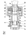
- Fig. 1 Eine Verschliessvorrichtung mit den Merkmalen der Erfindung im Schnitt,
- Fig. 2 die abtriebsseitige Kupplungsscheibe aus Fig. 1 in Draufsicht,
- Fig. 3 die Kupplungsscheibe gemäss Fig. 2 im Schnitt,
- Fig. 4 eine schematische Darstellung von Axial-Spiel und Toleranzen der Kupplung, und
- Fig. 5 eine schematische Darstellung des Einflusses von Spiel und Toleranzen auf das Drehmoment.
- Gemäss Fig. 1 weist die dargestellte Verschliessvorrichtung ein äusseres Kupplungsteil 1 auf, welches auf ein zylindrisches Zentral teil 2 aufgeschraubt ist. Das Zentral teil 2 ist axial verschiebbar an einem antriebsseitigen Anschlussteil 3 befestigt, welches in bekannter Weise an eine nicht dargestellte Antriebseinrichtung angeflanscht werden kann. Am Zentralteil 2 sind Stifte 4 vorgesehen, welche in Längsschlitzen 5 des Anschlussteils 3 verschiebbar sind. Am Anschlussteil 3 ist ausserdem eine umlaufende Schulter 6 vorgesehen, welche eine Feder 7 abstützt, die andererseits am Zentralteil 2 anliegt. Ersichtlicherweise kann dadurch das Zentral teil 2 in Längsrichtung gegen die Kraft der Feder 7 teleskopartig im Anschlussteil 3 verschoben werden, wobei durch die in den Längsschlitzen 5 gleitenden Stifte 4 sowohl der Längshub begrenzt wird, als auch das Drehmoment vom Anschlussteil 3 auf das Zentralteil 2 übertragen wird.
- Die Feder 7 und die Längsbewegbarkeit des äusseren Kupplungsteils 1 gegenüber dem Anschlussteil 3 ist in bekannter Weise deshalb vorgesehen, um die Kupplung beim Aufsetzvorgang- an Toleranzen in der Flaschenhöhe anzupasen und um insbesondere auch den Weg des Schraubverschlusses beim Aufschrauben auf die Flasche aufzunehmen. Selbstverständlich kann statt der Feder 7 auch eine andere Ausgleichsvorrichtung, z.B. hydraulischer Art, vorgesehen werden. Die Ausgleichsvorrichtung ist ohne Einfluss auf die vorliegende Erfindung.
- Im Zentralteil 2 ist ein Wälzlager 8 angeordnet, welches ein inneres Kupplungsteil 9 trägt. Das innere Kupplungsteil 9 ist mit einem konisch ausgebildeten Aufschraubkopf 10 versehen, der in bekannter Weise zur Aufnahme eines Schraubverschlusses 16 und zu dessen form- und/oder kraftschlüssigen Ergreifen während des Aufschraubvorgangs ausgebildet ist. Der im Wälzlager 8 drehbar gelagerte Aufschraubkopf 10 ist mit einer abtriebsseitigen Kupplungsscheibe 11 verbunden, welche eine Vielzahl von Permanent-Magneten 12 trägt. Das äussere Kupplungsteil 1 ist andererseits mit einer antriebsseitigen Kupplungsscheibe 13 versehen, auf welcher ebenfalls eine Vielzahl von Permanent-Magneten 14 angeordnet sind. Zwischen den beiden Kupplungsscheiben 11 und 13 befindet sich ein Luftspalt 15.
- Wie aus Fig. 2 und 3 ersichtlich ist, sind die Magnete 12 scheibenförmige Oxidmagnete, welche auf einem konzentrischen Kreis auf der Kupplungsscheibe 11 angeordnet sind. Die Polaritäten der Magnete 12 wechseln dabei derart ab, dass abwechselnd ein Nordpol und ein Südpol aufeinander folgt. Die Zwischenräume 12a zwischen den Magneten 12 sind vollständig mit einem erhärtenden Kunststoff (Araldit) ausgegossen und die Kupplungsscheibe 11 ist nach oben durch eine Abdeckung 18 aus Messing abgedeckt, welche in einen Ring 18a übergeht, welcher die Kupplungsscheibe 11 und die Magnete 12 am Umfang umgibt. Die Magnete sind damit sowohl gegen Stoss gesichert, als auch mechanisch fest zwischen der Schulter llc der Kupplungsscheibe 11 einerseits und dem Ring 18a der Abdeckung andererseits gehalten.
- Die nicht in Ansicht dargestellte abtriebsseitige Kupplungsscheibe 13 ist in der Konfiguration identisch mit der Kupplungsscheibe 11. Dementsprechend wird sich die abtriebsseitige Kupplungsscheibe 13, die am Inneren Kupplungsteil 9 befestigt und mit diesem im Wälzlager 8 frei drehbar gelagert ist, im Ruhezustand in eine Position einstellen, bei welcher sich jeweils Nord/Südmagnete der beiden Kupplungsscheiben 11 und 13 gegenüberliegen. Die Anziehungskraft zwischen den beiden Kupplungsscheiben wird durch die Dimensionierung der Magnete, sowie die Grösse des Luftspalts 15 bestimmt. Die Dimensionierung der Magnetanordnung in Abhängigkeit vom Soll-Drehmoment ist Stand der Technik und dem Fachmann geläufig. Durch die grosse Anzahl von Magneten auf jeder Kupplungsscheibe 11, 13 wird vorteilhaft sicher gestellt, dass bei einer Drehung der beiden Kupplungsscheiben 11, 13, gegeneinander der Abstand zwischen zwei aufeinander folgenden Polen derart gering ist, dass ein "Rattern" der Kupplungsscheibe 13, bzw. des Aufschraubkopfs 10 vermieden wird. Dadurch werden stark ansteigende, bzw. abfallende Aenderungen des Drehmomentverlaufs beim Durchdrehen der Kupplung vermieden, wodurch Beschädigungen des Schraubverschlusses 11 ausgeschlossen werden. Besonders bewährt haben sich dabei Kupplungsanordnungen mit zehn bis vierzehn Magneten.
- Durch das Eingiessen der Magnete 12, bzw. 14 im Ringspalt zwischen der Abdeckung 18 und der Kupplungsscheibe 11 wird auf optimal einfache Weise ein Kupplungsbauteil geschaffen, bei dem die Magnete gegenüber mechanischen Beanspruchungen, z.B. durch Stoss beim Zusammenbau, geschützt sind. Ausserdem wird durch das Eingiessen der Magnete 12 (und 14, nicht dargestellt) in Kunststoff sichergestellt, dass nicht nachträglich durch Verunreinigungen, z.B. Metallspäne und dergleichen, ein Nebenschluss zwischen den Magneten entsteht, welcher die im Luftspalt 15 wirkende Kraft beeinträchtigen könnte.
- Der Luftspalt 15 den Magneten 12 und 14 beträgt beim Ausführungsbeispiel etwa 4 mm. Der effektive Abstand zwischen den Magneten beträgt jedoch ca. 6 mm, da die Messing-Abdeckung 18 sich ebenfalls im Raum zwischen den Magneten 12 und 14 befinden. Der effektive Abstand beträgt etwa 6 mm. Durch diesen relativ grossen Abstand wird vorteilhafterweise sichergestellt, dass Lagertoleranzen und Spiel in der Gesamtanordnung nur unbedeutenden Einfluss auf das übertragbare Drehmoment haben.
- Aus Fig. 4 ist ersichtlich, wie sich die Toleranzen von Antriebsseite (Kupplungsscheibe 11, Abdeckung 18), Abtriebsseite (Kupplungsscheibe 13, Abdeckung 18, Abstandsring 17) und die Toleranz des Wälzlagers 8 sowie dessen Spiel addieren. Wesentlich ist es, dass bei der Dimensionierung der Kupplungsanordnung der Abstand zwischen den Magneten 12 und 14 wenigstens sechsmal so gross ist, wie die Toleranzen Tl (Antriebsseite), T2 (Abtriebsseite), T3 (Wälzlager) sowie das Wälzlagerspiel S1 (Fig. 4). Dadurch wird gewährleistet, dass auf vorteilhafte Weise der Drehmomentverlauf durch Bauteiltoleranzen nur in geringem Masse beeinflusst wird. Dies erübrigt spezielle Anpassung der Kupplung und der Kupplungsbauteile im Rahmen des Herstellungsvorgangs und erlaubt wirtschaftliche Serienfertigung der Verschliessvorrichtung. In der Praxis hat sich ausserdem gezeigt, dass diese Dimensionierung erst den praktischen Einsatz der Kupplung ermöglicht. Da bei Verschliessvorrichtungen für Flaschenverschlüsse durch die vertikale Belastung des Aufschraubkopfs 10 gegen den Druck der Feder 7 eine starke axiale Belastung sämtlicher beweglicher Teile, einschliesslich der die Toleranzen Tl bis T3 und das Spiel S1 beeinflussenden Teil auftritt, ist im Gegensatz zu den üblicherweiser stationär angeordneten herkömmlichen Magnetkupplungen eine Veränderung der Toleranzen Tl bis T3 und des Spiels S1 durch Verschleisserscheinungen zu beobachten. Der Einsatz von Magnetkupplungen, deren Kraftübertragungs-Charakteristik ausschlaggebend vom Luftspalt, bzw. vom Wirkabstand zwischen den Magnetreihen abhängt, wurde unter anderem deshalb für Verschliessvorrichtungen für nicht möglich erachtet.
- Fig. 5 zeigt ein schematisches Diagramm, aus welchem der Verlauf der Drehmoment-Uebertragungscharakteristik der Kupplungsanordnung in Abhängigkeit vom Toleranzfeld (einschliesslich zusätzlicher Toleranzen durch Verschleisserscheinungen) darstellt. Daraus ist ersichtlich, dass durch die Wahl des grossen Luftspalts, bzw. des Abstands zwischen den Magnetreihen der Drehmomentverlauf kaum beeinflusst wird. Drehmomentänderungen treten demnach bei Schwankungen T des Axialabstands nur ausserordentlich geringfügig auf. Eine derartige Dimensionierung liegt dem Fachmann an sich fern, da der Fachmann normalerweise bestrebt sein wird, den Luftspalt so gering als möglich zu halten, um möglichst grosse Kraft, bzw. Drehmomentübertragung zu erreichen und die Magnete 12 und 14 klein dimensionieren zu n Von diesem Prinzip rückt die Erfindung bewusst ab und schlägt einen Luftspalt, bzw. einen Abstand zwischen den Magnetreihen vor, welcher wenigstens sechsmal grösser ist, als die maximal zu erwartenden Toleranzen in Axialrichtung.
- Der Einfluss von Schwankungen Tx des Axialabstands auf das Drehmoment x bei einer derartigen "konventionellen" Auslegung ist in Fig. 5 ebenfalls angedeutet.
- Ersichtlicherweise schafft die Erfindung damit eine Verschliessvorrichtung, die einfach im Aufbau ist, die sich in der Serienherstellung wirtschaftlich fertigen lässt und die darüber hinaus verschleissfrei ist und gleichmässigen Drehmomentverlauf sichert.
Claims (15)
Priority Applications (1)
| Application Number | Priority Date | Filing Date | Title |
|---|---|---|---|
| AT80810128T ATE8376T1 (de) | 1979-04-25 | 1980-04-17 | Verschliessvorrichtung zum aufschrauben eines kunststoff-schraubverschlusses. |
Applications Claiming Priority (3)
| Application Number | Priority Date | Filing Date | Title |
|---|---|---|---|
| CH3885/79 | 1979-04-25 | ||
| CH388579A CH636063A5 (de) | 1979-04-25 | 1979-04-25 | Verschliessvorrichtung zum aufschrauben eines kunststoff-schraubverschlusses. |
| AU24897/84A AU2489784A (en) | 1979-04-25 | 1984-02-23 | Apparatus for screwing on a plastics screw closure |
Publications (3)
| Publication Number | Publication Date |
|---|---|
| EP0018944A2 true EP0018944A2 (de) | 1980-11-12 |
| EP0018944A3 EP0018944A3 (en) | 1981-01-28 |
| EP0018944B1 EP0018944B1 (de) | 1984-07-11 |
Family
ID=25619488
Family Applications (1)
| Application Number | Title | Priority Date | Filing Date |
|---|---|---|---|
| EP80810128A Expired EP0018944B1 (de) | 1979-04-25 | 1980-04-17 | Verschliessvorrichtung zum Aufschrauben eines Kunststoff-Schraubverschlusses |
Country Status (7)
| Country | Link |
|---|---|
| EP (1) | EP0018944B1 (de) |
| JP (1) | JPS55154285A (de) |
| AU (2) | AU534331B2 (de) |
| CA (1) | CA1144788A (de) |
| CH (1) | CH636063A5 (de) |
| DE (2) | DE2930891A1 (de) |
| ES (1) | ES490859A0 (de) |
Cited By (7)
| Publication number | Priority date | Publication date | Assignee | Title |
|---|---|---|---|---|
| EP0061095A1 (de) * | 1981-03-25 | 1982-09-29 | Etablissements Andre Zalkin Et Cie | Rutschschraubkopf mit gesteuertem Drehmoment zum Anbringen von Kapseln |
| FR2518982A1 (fr) * | 1981-12-28 | 1983-07-01 | Owens Illinois Inc | Dispositif a mecanisme limiteur de couple pour le vissage de bouchons filetes sur le goulot de recipients |
| WO1986002917A1 (fr) * | 1984-11-16 | 1986-05-22 | Ernst Wiedmer | Tete de fermeture d'une installation de remplissage de bouteilles de boisson |
| DE3500945A1 (de) * | 1985-01-14 | 1986-07-17 | Verpackungssysteme AG, Schaffhausen | Drehmomentbegrenzende kupplung |
| CN104500609A (zh) * | 2014-12-26 | 2015-04-08 | 常熟市喆宏机械科技有限公司 | 扭力限制器 |
| CN112279179A (zh) * | 2020-11-03 | 2021-01-29 | 湖南精正同业机械有限公司 | 一种新型顶压下置恒扭矩旋盖头 |
| EP3828128A1 (de) * | 2019-11-28 | 2021-06-02 | Krones Ag | Vorrichtung und verschliessvorrichtung zum verschliessen eines behälters mit einem schraubverschluss |
Family Cites Families (3)
| Publication number | Priority date | Publication date | Assignee | Title |
|---|---|---|---|---|
| US2481172A (en) * | 1948-05-17 | 1949-09-06 | Jesse D Staggs | Magnetically driven fluidhandling device |
| CH313871A (de) * | 1951-11-28 | 1956-05-15 | Philips Nv | Einrichtung mit mindestens einem Körper aus Dauermagnetmaterial |
| US3899762A (en) * | 1974-10-03 | 1975-08-12 | Permag Magnetics Corp | Permanent magnetic structure |
-
1979
- 1979-04-25 CH CH388579A patent/CH636063A5/de not_active IP Right Cessation
- 1979-07-30 DE DE19792930891 patent/DE2930891A1/de not_active Withdrawn
-
1980
- 1980-04-17 EP EP80810128A patent/EP0018944B1/de not_active Expired
- 1980-04-17 DE DE8080810128T patent/DE3068499D1/de not_active Expired
- 1980-04-22 JP JP5346180A patent/JPS55154285A/ja active Pending
- 1980-04-22 AU AU57689/80A patent/AU534331B2/en not_active Ceased
- 1980-04-24 ES ES490859A patent/ES490859A0/es active Granted
- 1980-04-24 CA CA000350613A patent/CA1144788A/en not_active Expired
-
1984
- 1984-02-23 AU AU24897/84A patent/AU2489784A/en not_active Abandoned
Cited By (9)
| Publication number | Priority date | Publication date | Assignee | Title |
|---|---|---|---|---|
| EP0061095A1 (de) * | 1981-03-25 | 1982-09-29 | Etablissements Andre Zalkin Et Cie | Rutschschraubkopf mit gesteuertem Drehmoment zum Anbringen von Kapseln |
| FR2502605A1 (fr) * | 1981-03-25 | 1982-10-01 | Zalkin Andre & Cie | Tete visseuse a friction controlee par couple de torsion pour la mise en place de capsules |
| FR2518982A1 (fr) * | 1981-12-28 | 1983-07-01 | Owens Illinois Inc | Dispositif a mecanisme limiteur de couple pour le vissage de bouchons filetes sur le goulot de recipients |
| WO1986002917A1 (fr) * | 1984-11-16 | 1986-05-22 | Ernst Wiedmer | Tete de fermeture d'une installation de remplissage de bouteilles de boisson |
| DE3500945A1 (de) * | 1985-01-14 | 1986-07-17 | Verpackungssysteme AG, Schaffhausen | Drehmomentbegrenzende kupplung |
| CN104500609A (zh) * | 2014-12-26 | 2015-04-08 | 常熟市喆宏机械科技有限公司 | 扭力限制器 |
| EP3828128A1 (de) * | 2019-11-28 | 2021-06-02 | Krones Ag | Vorrichtung und verschliessvorrichtung zum verschliessen eines behälters mit einem schraubverschluss |
| CN112279179A (zh) * | 2020-11-03 | 2021-01-29 | 湖南精正同业机械有限公司 | 一种新型顶压下置恒扭矩旋盖头 |
| CN112279179B (zh) * | 2020-11-03 | 2024-06-11 | 湖南精正同业机械有限公司 | 一种新型顶压下置恒扭矩旋盖头 |
Also Published As
| Publication number | Publication date |
|---|---|
| CH636063A5 (de) | 1983-05-13 |
| JPS55154285A (en) | 1980-12-01 |
| EP0018944B1 (de) | 1984-07-11 |
| AU534331B2 (en) | 1984-01-19 |
| ES8102981A1 (es) | 1981-02-16 |
| DE2930891A1 (de) | 1980-11-06 |
| DE3068499D1 (en) | 1984-08-16 |
| EP0018944A3 (en) | 1981-01-28 |
| AU2489784A (en) | 1984-06-07 |
| CA1144788A (en) | 1983-04-19 |
| ES490859A0 (es) | 1981-02-16 |
| AU5768980A (en) | 1981-08-13 |
Similar Documents
| Publication | Publication Date | Title |
|---|---|---|
| DE3245966C2 (de) | Verschlußvorrichtung zum Aufschrauben von Verschlußkappen auf Behälter | |
| DE3014692C2 (de) | Magnetisch betätigbares stopfbüchsenloses Hochdruckventil | |
| DE19642446C2 (de) | Vorrichtung zum Halten zweier Bauteile in einer Abstandslage zueinander | |
| DE19912431A1 (de) | Ausrückvorrichtung | |
| EP0018944B1 (de) | Verschliessvorrichtung zum Aufschrauben eines Kunststoff-Schraubverschlusses | |
| DE2932661A1 (de) | Kupplung | |
| DE4118778C2 (de) | Staurollenbahn zum Transport von Fördergut | |
| DE3224759A1 (de) | Stirnzahnkupplung mit elektromagnetischer betaetigung | |
| DE3208182C2 (de) | ||
| DE4236428A1 (en) | Magnetically actuated torque limiting coupling - has driving cylinder between cylinders with inner and outer rings of magnets permitting relative rotation for torque adjustment | |
| DE2516947A1 (de) | Sicherheitskupplung | |
| DE1675159B2 (de) | Als Rückstellfeder wirkende Scheibenfeder für die Ankerscheibe einer elektromagnetisch betätigten Reibungskupplung mit auf dem Umfange gleichmäßig verteilten Ausnehmungen | |
| DE1114917B (de) | Magnetkupplung | |
| DE19600545B4 (de) | Formschlüssig arbeitende Überlastkupplung mit magnetischer innerer Haltekraft | |
| DE2649252A1 (de) | Regelbares, elektromagnetisches kupplungs- und/oder bremssystem und verfahren zu seiner einstellung | |
| DE3543025A1 (de) | Bewegliche kupplung | |
| DE4234596C2 (de) | Elektromagnetische Kupplung | |
| DE202014102645U1 (de) | Drehschwingungsdämpfer sowie Drehschwingungsdämpfersystem | |
| EP3828128B1 (de) | Vorrichtung und verschliessvorrichtung zum verschliessen eines behälters mit einem schraubverschluss | |
| EP0541187B1 (de) | Einrichtung zum Abbremsen einer Drehbewegung | |
| DE3048010A1 (de) | "drehmaschine, insbesondere horizontal-drehbank" | |
| DE4132164A1 (de) | Gleitringdichtung fuer eine welle einer pumpe o. dgl. | |
| WO1986002917A1 (fr) | Tete de fermeture d'une installation de remplissage de bouteilles de boisson | |
| DE7605936U1 (de) | Impuls-positionsgeber fuer naehmaschinen | |
| DE1809127C3 (de) | Antrieb für eine zwischen Endstellungen hin- und hergehende Bewegung |
Legal Events
| Date | Code | Title | Description |
|---|---|---|---|
| PUAI | Public reference made under article 153(3) epc to a published international application that has entered the european phase |
Free format text: ORIGINAL CODE: 0009012 |
|
| AK | Designated contracting states |
Designated state(s): AT BE DE FR GB IT LU NL SE |
|
| PUAL | Search report despatched |
Free format text: ORIGINAL CODE: 0009013 |
|
| AK | Designated contracting states |
Designated state(s): AT BE DE FR GB IT LU NL SE |
|
| 17P | Request for examination filed |
Effective date: 19801224 |
|
| ITF | It: translation for a ep patent filed | ||
| GRAA | (expected) grant |
Free format text: ORIGINAL CODE: 0009210 |
|
| AK | Designated contracting states |
Designated state(s): AT BE DE FR GB IT LU NL SE |
|
| REF | Corresponds to: |
Ref document number: 8376 Country of ref document: AT Date of ref document: 19840715 Kind code of ref document: T |
|
| REF | Corresponds to: |
Ref document number: 3068499 Country of ref document: DE Date of ref document: 19840816 |
|
| ET | Fr: translation filed | ||
| BECN | Be: change of holder's name |
Effective date: 19840711 |
|
| PLBI | Opposition filed |
Free format text: ORIGINAL CODE: 0009260 |
|
| 26 | Opposition filed |
Opponent name: ALCOA DEUTSCHLAND GMBH Effective date: 19850328 |
|
| NLR1 | Nl: opposition has been filed with the epo |
Opponent name: ALCOA DEUTSCHLAND GMBH |
|
| RAP2 | Party data changed (patent owner data changed or rights of a patent transferred) |
Owner name: CROWN OBRIST AG |
|
| PLBM | Termination of opposition procedure: date of legal effect published |
Free format text: ORIGINAL CODE: 0009276 |
|
| STAA | Information on the status of an ep patent application or granted ep patent |
Free format text: STATUS: OPPOSITION PROCEDURE CLOSED |
|
| NLT2 | Nl: modifications (of names), taken from the european patent patent bulletin |
Owner name: CROWN OBRIST AG TE REINACH, ZWITSERLAND. |
|
| 27C | Opposition proceedings terminated |
Effective date: 19860426 |
|
| ITTA | It: last paid annual fee | ||
| EPTA | Lu: last paid annual fee | ||
| NLR2 | Nl: decision of opposition | ||
| EAL | Se: european patent in force in sweden |
Ref document number: 80810128.1 |
|
| PGFP | Annual fee paid to national office [announced via postgrant information from national office to epo] |
Ref country code: SE Payment date: 19950210 Year of fee payment: 16 |
|
| PGFP | Annual fee paid to national office [announced via postgrant information from national office to epo] |
Ref country code: AT Payment date: 19950214 Year of fee payment: 16 |
|
| PGFP | Annual fee paid to national office [announced via postgrant information from national office to epo] |
Ref country code: LU Payment date: 19950301 Year of fee payment: 16 |
|
| PGFP | Annual fee paid to national office [announced via postgrant information from national office to epo] |
Ref country code: BE Payment date: 19950314 Year of fee payment: 16 |
|
| PGFP | Annual fee paid to national office [announced via postgrant information from national office to epo] |
Ref country code: GB Payment date: 19950403 Year of fee payment: 16 |
|
| PGFP | Annual fee paid to national office [announced via postgrant information from national office to epo] |
Ref country code: NL Payment date: 19950430 Year of fee payment: 16 |
|
| PG25 | Lapsed in a contracting state [announced via postgrant information from national office to epo] |
Ref country code: LU Free format text: LAPSE BECAUSE OF NON-PAYMENT OF DUE FEES Effective date: 19960417 Ref country code: GB Effective date: 19960417 Ref country code: AT Effective date: 19960417 |
|
| PG25 | Lapsed in a contracting state [announced via postgrant information from national office to epo] |
Ref country code: SE Effective date: 19960418 |
|
| PG25 | Lapsed in a contracting state [announced via postgrant information from national office to epo] |
Ref country code: BE Effective date: 19960430 |
|
| BERE | Be: lapsed |
Owner name: CROWN OBRIST A.G. Effective date: 19960430 |
|
| PG25 | Lapsed in a contracting state [announced via postgrant information from national office to epo] |
Ref country code: NL Effective date: 19961101 |
|
| GBPC | Gb: european patent ceased through non-payment of renewal fee |
Effective date: 19960417 |
|
| NLV4 | Nl: lapsed or anulled due to non-payment of the annual fee |
Effective date: 19961101 |
|
| EUG | Se: european patent has lapsed |
Ref document number: 80810128.1 |
|
| PGFP | Annual fee paid to national office [announced via postgrant information from national office to epo] |
Ref country code: FR Payment date: 19980312 Year of fee payment: 19 |
|
| PGFP | Annual fee paid to national office [announced via postgrant information from national office to epo] |
Ref country code: DE Payment date: 19980325 Year of fee payment: 19 |
|
| PG25 | Lapsed in a contracting state [announced via postgrant information from national office to epo] |
Ref country code: FR Free format text: LAPSE BECAUSE OF NON-PAYMENT OF DUE FEES Effective date: 19991231 |
|
| REG | Reference to a national code |
Ref country code: FR Ref legal event code: ST |
|
| PG25 | Lapsed in a contracting state [announced via postgrant information from national office to epo] |
Ref country code: DE Free format text: LAPSE BECAUSE OF NON-PAYMENT OF DUE FEES Effective date: 20000201 |