EP0019005A1 - Verfahren und Vorrichtung zum Herstellen von Verpackungsbehältern für Suppositorien - Google Patents
Verfahren und Vorrichtung zum Herstellen von Verpackungsbehältern für Suppositorien Download PDFInfo
- Publication number
- EP0019005A1 EP0019005A1 EP79101454A EP79101454A EP0019005A1 EP 0019005 A1 EP0019005 A1 EP 0019005A1 EP 79101454 A EP79101454 A EP 79101454A EP 79101454 A EP79101454 A EP 79101454A EP 0019005 A1 EP0019005 A1 EP 0019005A1
- Authority
- EP
- European Patent Office
- Prior art keywords
- cells
- fact
- tapes
- band
- shaping
- Prior art date
- Legal status (The legal status is an assumption and is not a legal conclusion. Google has not performed a legal analysis and makes no representation as to the accuracy of the status listed.)
- Granted
Links
- 238000000034 method Methods 0.000 title claims abstract description 22
- 239000000829 suppository Substances 0.000 title claims abstract description 17
- 238000004519 manufacturing process Methods 0.000 title claims abstract description 8
- 238000007493 shaping process Methods 0.000 claims abstract description 29
- 238000007664 blowing Methods 0.000 claims abstract description 14
- 238000003466 welding Methods 0.000 claims abstract description 9
- 239000012815 thermoplastic material Substances 0.000 claims abstract description 5
- 238000003860 storage Methods 0.000 claims abstract 3
- 238000010438 heat treatment Methods 0.000 claims description 9
- 238000005304 joining Methods 0.000 claims description 8
- 238000001816 cooling Methods 0.000 claims description 6
- 238000007639 printing Methods 0.000 claims description 5
- 238000003825 pressing Methods 0.000 claims description 2
- 239000012530 fluid Substances 0.000 claims 1
- 230000001360 synchronised effect Effects 0.000 claims 1
- 238000004804 winding Methods 0.000 claims 1
- 238000000071 blow moulding Methods 0.000 abstract 1
- 238000002360 preparation method Methods 0.000 description 5
- 239000000463 material Substances 0.000 description 3
- 238000005520 cutting process Methods 0.000 description 2
- 238000000465 moulding Methods 0.000 description 2
- 238000004080 punching Methods 0.000 description 2
- 238000007792 addition Methods 0.000 description 1
- 239000012809 cooling fluid Substances 0.000 description 1
- 238000010586 diagram Methods 0.000 description 1
- 239000002184 metal Substances 0.000 description 1
- 238000012986 modification Methods 0.000 description 1
- 230000004048 modification Effects 0.000 description 1
- 238000012856 packing Methods 0.000 description 1
- 239000000825 pharmaceutical preparation Substances 0.000 description 1
- 229940127557 pharmaceutical product Drugs 0.000 description 1
- 239000004033 plastic Substances 0.000 description 1
- 238000007789 sealing Methods 0.000 description 1
- 238000006467 substitution reaction Methods 0.000 description 1
Images


Classifications
-
- A—HUMAN NECESSITIES
- A61—MEDICAL OR VETERINARY SCIENCE; HYGIENE
- A61J—CONTAINERS SPECIALLY ADAPTED FOR MEDICAL OR PHARMACEUTICAL PURPOSES; DEVICES OR METHODS SPECIALLY ADAPTED FOR BRINGING PHARMACEUTICAL PRODUCTS INTO PARTICULAR PHYSICAL OR ADMINISTERING FORMS; DEVICES FOR ADMINISTERING FOOD OR MEDICINES ORALLY; BABY COMFORTERS; DEVICES FOR RECEIVING SPITTLE
- A61J3/00—Devices or methods specially adapted for bringing pharmaceutical products into particular physical or administering forms
- A61J3/08—Devices or methods specially adapted for bringing pharmaceutical products into particular physical or administering forms into the form of suppositories or sticks
-
- B—PERFORMING OPERATIONS; TRANSPORTING
- B29—WORKING OF PLASTICS; WORKING OF SUBSTANCES IN A PLASTIC STATE IN GENERAL
- B29C—SHAPING OR JOINING OF PLASTICS; SHAPING OF MATERIAL IN A PLASTIC STATE, NOT OTHERWISE PROVIDED FOR; AFTER-TREATMENT OF THE SHAPED PRODUCTS, e.g. REPAIRING
- B29C49/00—Blow-moulding, i.e. blowing a preform or parison to a desired shape within a mould; Apparatus therefor
- B29C49/02—Combined blow-moulding and manufacture of the preform or the parison
- B29C49/06905—Using combined techniques for making the preform
- B29C49/0691—Using combined techniques for making the preform using sheet like material, e.g. sheet blow-moulding from joined sheets
-
- B—PERFORMING OPERATIONS; TRANSPORTING
- B29—WORKING OF PLASTICS; WORKING OF SUBSTANCES IN A PLASTIC STATE IN GENERAL
- B29C—SHAPING OR JOINING OF PLASTICS; SHAPING OF MATERIAL IN A PLASTIC STATE, NOT OTHERWISE PROVIDED FOR; AFTER-TREATMENT OF THE SHAPED PRODUCTS, e.g. REPAIRING
- B29C49/00—Blow-moulding, i.e. blowing a preform or parison to a desired shape within a mould; Apparatus therefor
- B29C49/42—Component parts, details or accessories; Auxiliary operations
- B29C49/48—Moulds
- B29C49/4823—Moulds with incorporated heating or cooling means
-
- B—PERFORMING OPERATIONS; TRANSPORTING
- B29—WORKING OF PLASTICS; WORKING OF SUBSTANCES IN A PLASTIC STATE IN GENERAL
- B29C—SHAPING OR JOINING OF PLASTICS; SHAPING OF MATERIAL IN A PLASTIC STATE, NOT OTHERWISE PROVIDED FOR; AFTER-TREATMENT OF THE SHAPED PRODUCTS, e.g. REPAIRING
- B29C49/00—Blow-moulding, i.e. blowing a preform or parison to a desired shape within a mould; Apparatus therefor
- B29C49/42—Component parts, details or accessories; Auxiliary operations
- B29C49/58—Blowing means
-
- B—PERFORMING OPERATIONS; TRANSPORTING
- B29—WORKING OF PLASTICS; WORKING OF SUBSTANCES IN A PLASTIC STATE IN GENERAL
- B29C—SHAPING OR JOINING OF PLASTICS; SHAPING OF MATERIAL IN A PLASTIC STATE, NOT OTHERWISE PROVIDED FOR; AFTER-TREATMENT OF THE SHAPED PRODUCTS, e.g. REPAIRING
- B29C49/00—Blow-moulding, i.e. blowing a preform or parison to a desired shape within a mould; Apparatus therefor
- B29C49/42—Component parts, details or accessories; Auxiliary operations
- B29C49/48—Moulds
- B29C49/48185—Moulds with more than one separate mould cavity
Definitions
- the present invention relates to a method allowing to pro- f cute shells or envelopes for suppositories in a particularly advantageous way as well as an apparatus for carrying out said method.
- the envelopes or shells for suppositories are consisting of the cell, i.e. the portion having the characteristic shape of an ogive and the volume corresponding to the dosage of pharmaceutical product to be administered, and the bell i.e. that funnel shaped portion through which filling of the cell is effected and then is closed generally by welding or sometimes by a sealing strip.
- the shells are produced by joining two continuous tapes of thermoplastic material and making the cells on them by heating and molding or blowing. As a general rule from each tape two continuous rows of oppositely arranged cells are obtained, which are then generally severed at the moment of preparing the suppositories.
- the present invention removes the drawbacks of both these systems adopted up to now, and is the ideal compromise solution avoiding high costs of carrying already shaped shells and at the same time not requiring the high cost of installing a manufacturing machine at each pharmaceutical industry, thus giving a brilliant compromise which is the ideal solution for everybody but more particularly for pharmaceutical industries of small and medium size.
- the method according to the present invention substantially consists in joining two continuos tapes of thermoplastic material, making on one of said tapes central holes having a spacing equal to that of the cells and then carrying out joining of the tapes by electronic or thermal welding, at the same time obtaining the outline of the cells which will then be shaped, thus obtaining a continuous band having the plan outline of the cells but still being flat, so as to be transported with little room, and thereafter effecting shaping of the cells by heating the band and blowing air between the two tapes while they are in a mould through said holes made in one of the two tapes, so as to inflate and bring the outline of the cells to their final shape ready for preparation of the suppositories.
- shaping of the cells is effected at the plant of the pharmaceutical industry preparing the suppositories and this operation may be effected with a very simple apparatus of reduced size and moderate cost, within the reach of any small pharmaceutical industry.
- the apparatus for shaping the cells substantially consists of a mould made of two parts or dies closing around the band formed by the two joined tapes and previously heated, each die bearing the cavities of the hemiogives to be made; the part of the mould or die, adapted to be contacted with the tape on which the central holes were previously made, has a suction system, adapted to keep the tape adhering during the operation of shaping the cells, and a blowing system to shape said cells.
- the apparatus provides also means for cooling the mould and means for timed advancement of the band,exactly in register with the cavities of the dies.
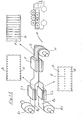
- the method of the present invention substantially comprises the following steps: starting from two feeding rolls A and A of a tape of thermoplastic material, two tapes B and B 2 to be joined, are obtained.
- the first operation carried out on tapes B 1 and B 2 is punching by means of suitable punching dies or plates C 1 and C 2 ; while one of the tapes (B 1 ) receives only two rows of punches on the lateral edges, to obtain perforations D like those of photographic or cinematographic films, so as to allow during the step of shaping the cells, the advancement of the tapes in perfect timing and register with the cavities of the shaping die, the other tape (B 2 ) in addition to said lateral perforations, receives also a row of central perforations E with a spacing equal to that of the outline of the cells to be shaped.
- the lateral perforations D and the central perforations E are aligned and have the same spacing.
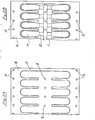
- the two tapes B 1 and B 2 then go to the actual joining step, carried out by electronic or thermal welding F leaving on the joined tapes the flat outline of two oppositely arranged groups of cells, each group containing a number of cells equal to that being produced at each blow of the shaping mould.
- the band G is obtained, formed by the two joined tapes and bearing the perforations and the outline ; of the cells to be shaped, as illustrated in Fig. 2A.
- This band is wound into rolls H or lengths and is therefore ready ; for being delivered to the user with the minimum possible room consumption.
- the roll H is unwound and first goes to the printing station I where a printing machine of known type prints the captions on the tape; this operation may be effected at one oppositely arranged twin cell for each blow or by groups of cells. In any case it is preferred that the operation of printing the captions is not strictly bound to the subsequent step of shaping the cells and therefore a loop or reserve J of material is provided between the printing - station I and the subsequent steps which are the most important part of the method according to the present invention.
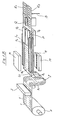
- the band G is catched and entrained by a couple of upper belts K 1 -K 2 and a couple of lower belts L 1 -L 2 ; one couple of belts is provided with cogs having a spacing equal to that of the lateral perforations D of the band G and are inserted into them, while the other couple of belts has a continuous channel pressing on the band G.
- the band G is moved in perfect timing and register with the station for shaping the cells.
- the band G Prior to shaping, the band G is heated at the heating station M by any system adapted to bring the material into a mouldable condition. It has to be pointed out that a device should be provided, adapted to keep cooled the central zone of the tape B 2 , where the central perforations E are made, so that this zone does not stick to the corresponding zone of the other tape B 1 under the influence of heat. As a matter of fact, this is essential in order that the air, which subsequently will be blown, may freely flow along the central channel T formed between the two oppositely arranged rows of cells.
- This device is preferably formed by a cooled metal blade N or similar thermal screen for this limited zone of the tape B 2 .
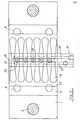
- the band G then goes to the shaping station, comprised of the apparatus which will be illustrated in its structural details with reference to Figs. 3-6 of the drawings, and at this shaping station the two dies O 1 -O 2 , bearing the cavities of the hemiogives of the cells, clamp the heated band G and shape the cells by blowing.
- the die (O 2 ) on which lies the tape (B 2 ) bearing the central perforations E has a suction system holding the tape adhering to it, while a blowing system, immediately after suction start, provides to blow air into the central perforations E so as to inflate and shape in the cavities of the dies, the cells whose outline contour is determined by the electronic welding.
- the electronic welding determines a general outline of the cell, in which the actual shape and size given by the cavities of the dies may be varied.
- the band G now bearing the shaped cells P passes over a slitter Q, so as to obtain two continuous rows R 1 -R 2 of cells, which are received in a suitable vessel or reservoir and thereafter are fed to the preparation line of the suppositories, preferably after being cut into long lengths e.g. of one thousand cells each, by means of a device S counting the cells and cutting the lengths.
- this device is dispensed with if the operation of cutting into lengths was already carried out by the manufacturer of the joined tapes.
- the various processing stations are comprised of very simple devices and generally of a type common in the treatment of tapes of plastic materials, excepting the blow shaping apparatus, which although it is very simple, economical and requiring little room, is especially devised for carrying out the method of the present invention and therefore is now described in detail with reference to Figures 3-6 of the accompanying drawings.
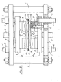
- the apparatus for shaping the cells comprises a rigid support frame formed by crosspieces 1-2 and tierods 3-4.
- Crosspieces 1-2 bear bushings 5 in which slide the columns 6 supporting the plates or beds 7 which are reciprocated by hydraulic cylinders 8 with their piston rods 9 whose head is secured to the corresponding bed 7.
- Each bed 7 bears a stationary mould or die 10 having the cavity for the bells 12 of the shells to be shaped, which always have the same sizes, whatever is the volume of the cell or ogive of the shell.
- the movable lateral I dies 13 are applied, containing the cavities for the hemiogives 14 of different sizes according to the type of suppository to be prepared.
- the movable lateral dies are movably fixed by means of bolts 15 passing through the holes 16 of beds 7 and accessible through the passages 17 made in the crosspieces 1-2.
- Beds 7 have a cooling system formed by passages 18, 19, 20, 21 and 22 made in their body and ending with the inlet connections 23 and outlet connections 24 for the lines of the cooling fluid circuit. It will be noted that the cooling circuit in the bed 7 is placed toward the inlet edge of the band G coming from the heating station M, so as to cool more the zone which is more subjected to heat.
- the die or mould 0 2 facing the tape B 2 provided with the central perforations E has also suction and blowing systems being the main features of the illustrated apparatus.
- this mould shows, at the center of each distance between two cavities of oppositely arranged bells 12, a groove 25 in the form of a ring provided with a little hole 26 communicating with the passage 27 in turn communicating with the line coming from the source of suction or negative pressure, so as to keep tape B 2 adhering during shaping in the die of the mould.
- the nozzle 28 At the center of each ring 25 there is the nozzle 28 as outlet of channels 29 communicating with passage 30 feeding pressurized air coming from a suitable source (not shown).
- die 0 2 has a protruding part 31 so as to allow the connection to the lines coming from the suction source and the pressurized air source, respectively.
- the opposite die 0 has a central channel 11 allowing tape B 1 to be inflated under the thrust of air coming out from nozzles 28 and to form therein the connection channel for the several cells of the same group. Air cannot escape from the two ends of this channel, as it is hindered by the perimetrical electronic welding of each group of shaped cells.
- the groove 25 must perform the function of surrounding the central holes E of tape B 2 and therefore may have any suitable perimetrical form, in addition to the circular one, e.g. a square or polygonal form, It is therefore easy to understand that the above described apparatus is a simple and reliable means for forming the cells, allowing to carry out the method of the present invention in a quick and economical manner.
Landscapes
- Engineering & Computer Science (AREA)
- Manufacturing & Machinery (AREA)
- Mechanical Engineering (AREA)
- Health & Medical Sciences (AREA)
- Animal Behavior & Ethology (AREA)
- Medicinal Chemistry (AREA)
- Pharmacology & Pharmacy (AREA)
- Life Sciences & Earth Sciences (AREA)
- Chemical & Material Sciences (AREA)
- General Health & Medical Sciences (AREA)
- Public Health (AREA)
- Veterinary Medicine (AREA)
- Containers And Plastic Fillers For Packaging (AREA)
- Blow-Moulding Or Thermoforming Of Plastics Or The Like (AREA)
- Pharmaceuticals Containing Other Organic And Inorganic Compounds (AREA)
- Medicinal Preparation (AREA)
- Lining Or Joining Of Plastics Or The Like (AREA)
Priority Applications (3)
| Application Number | Priority Date | Filing Date | Title |
|---|---|---|---|
| AT79101454T ATE6830T1 (de) | 1979-05-11 | 1979-05-11 | Verfahren und vorrichtung zum herstellen von verpackungsbehaeltern fuer suppositorien. |
| DE7979101454T DE2966853D1 (en) | 1979-05-11 | 1979-05-11 | Method and apparatus for the production of suppository shells |
| EP79101454A EP0019005B1 (de) | 1979-05-11 | 1979-05-11 | Verfahren und Vorrichtung zum Herstellen von Verpackungsbehältern für Suppositorien |
Applications Claiming Priority (1)
| Application Number | Priority Date | Filing Date | Title |
|---|---|---|---|
| EP79101454A EP0019005B1 (de) | 1979-05-11 | 1979-05-11 | Verfahren und Vorrichtung zum Herstellen von Verpackungsbehältern für Suppositorien |
Publications (2)
| Publication Number | Publication Date |
|---|---|
| EP0019005A1 true EP0019005A1 (de) | 1980-11-26 |
| EP0019005B1 EP0019005B1 (de) | 1984-03-28 |
Family
ID=8186117
Family Applications (1)
| Application Number | Title | Priority Date | Filing Date |
|---|---|---|---|
| EP79101454A Expired EP0019005B1 (de) | 1979-05-11 | 1979-05-11 | Verfahren und Vorrichtung zum Herstellen von Verpackungsbehältern für Suppositorien |
Country Status (3)
| Country | Link |
|---|---|
| EP (1) | EP0019005B1 (de) |
| AT (1) | ATE6830T1 (de) |
| DE (1) | DE2966853D1 (de) |
Cited By (7)
| Publication number | Priority date | Publication date | Assignee | Title |
|---|---|---|---|---|
| FR2559710A1 (fr) * | 1984-02-22 | 1985-08-23 | Contrapac | Procede et dispositif pour conserver la planeite des bordures libres en contact de feuilles soudees qui constituent une bande continue a alveoles |
| EP0229109A4 (de) * | 1985-06-18 | 1988-08-10 | Baxter Travenol Lab | Verfahren und einrichtung zur erzeugung von beckenwerksbändern. |
| EP0692364A1 (de) * | 1994-07-12 | 1996-01-17 | Unifill S.P.A. | Formen von Behältern in mehreren Blasformschritten |
| WO1998056660A3 (en) * | 1997-06-09 | 1999-03-04 | Unifill International Ag | Method and apparatus for making and advancing groups of containers |
| WO2001049472A3 (en) * | 1999-12-31 | 2001-12-20 | Elopak Systems | Forming of containers |
| WO2003043799A1 (en) * | 2001-11-23 | 2003-05-30 | Sarong Societa'per Azioni | Method and apparatus for forming containers |
| US7959851B2 (en) * | 2002-01-24 | 2011-06-14 | Sarong Societa' per Zioni | Method for forming strips of containers |
Citations (7)
| Publication number | Priority date | Publication date | Assignee | Title |
|---|---|---|---|---|
| DE957159C (de) * | 1952-11-29 | 1957-01-31 | Charles Nicolle | Verfahren und Vorrichtung zur Verpackung von spritzbaren Produkten |
| US2991500A (en) * | 1954-06-14 | 1961-07-11 | Hagen Norbert | Method and apparatus for making plastic containers |
| DE1461946A1 (de) * | 1965-08-13 | 1969-02-06 | Becton Dickinson Co | Maschine zum Herstellen von Verpackungen aus fortlaufendem Bandmaterial und zum Fuellen derselben mit Ware |
| DE1479014A1 (de) * | 1961-09-08 | 1969-02-13 | Crespi Dr Ing Franco | Verfahren und Einrichtung zur Herstellung von Giessform-Verpackungsbehaeltern,beispielsweise fuer Stuhlzaepfchen u.dgl. |
| DE2142034A1 (de) * | 1971-08-21 | 1973-03-01 | Franco Pozzi | Verfahren zur kontinuierlichen herstellung von behaeltern aus plastischem material, insbesondere fuer suppositorien u. dgl. und vorrichtung zur durchfuehrung des verfahrens |
| DE2251724A1 (de) * | 1971-10-25 | 1973-05-03 | Sarong Spa | Verfahren und einrichtung zur herstellung von aus folienbahnen gebildeten vielzelligen packungen, bei welchen die hergestellten zellen zur einfuellung mit dem verpackungsgut bestimmt sind |
| FR2201958A1 (en) * | 1972-10-06 | 1974-05-03 | Robache Roger | Prodn. of multiple pocket strip packaging - using equipment for continuously welding and inflating twin thermoplastic sheeting |
-
1979
- 1979-05-11 DE DE7979101454T patent/DE2966853D1/de not_active Expired
- 1979-05-11 EP EP79101454A patent/EP0019005B1/de not_active Expired
- 1979-05-11 AT AT79101454T patent/ATE6830T1/de not_active IP Right Cessation
Patent Citations (7)
| Publication number | Priority date | Publication date | Assignee | Title |
|---|---|---|---|---|
| DE957159C (de) * | 1952-11-29 | 1957-01-31 | Charles Nicolle | Verfahren und Vorrichtung zur Verpackung von spritzbaren Produkten |
| US2991500A (en) * | 1954-06-14 | 1961-07-11 | Hagen Norbert | Method and apparatus for making plastic containers |
| DE1479014A1 (de) * | 1961-09-08 | 1969-02-13 | Crespi Dr Ing Franco | Verfahren und Einrichtung zur Herstellung von Giessform-Verpackungsbehaeltern,beispielsweise fuer Stuhlzaepfchen u.dgl. |
| DE1461946A1 (de) * | 1965-08-13 | 1969-02-06 | Becton Dickinson Co | Maschine zum Herstellen von Verpackungen aus fortlaufendem Bandmaterial und zum Fuellen derselben mit Ware |
| DE2142034A1 (de) * | 1971-08-21 | 1973-03-01 | Franco Pozzi | Verfahren zur kontinuierlichen herstellung von behaeltern aus plastischem material, insbesondere fuer suppositorien u. dgl. und vorrichtung zur durchfuehrung des verfahrens |
| DE2251724A1 (de) * | 1971-10-25 | 1973-05-03 | Sarong Spa | Verfahren und einrichtung zur herstellung von aus folienbahnen gebildeten vielzelligen packungen, bei welchen die hergestellten zellen zur einfuellung mit dem verpackungsgut bestimmt sind |
| FR2201958A1 (en) * | 1972-10-06 | 1974-05-03 | Robache Roger | Prodn. of multiple pocket strip packaging - using equipment for continuously welding and inflating twin thermoplastic sheeting |
Cited By (8)
| Publication number | Priority date | Publication date | Assignee | Title |
|---|---|---|---|---|
| FR2559710A1 (fr) * | 1984-02-22 | 1985-08-23 | Contrapac | Procede et dispositif pour conserver la planeite des bordures libres en contact de feuilles soudees qui constituent une bande continue a alveoles |
| EP0229109A4 (de) * | 1985-06-18 | 1988-08-10 | Baxter Travenol Lab | Verfahren und einrichtung zur erzeugung von beckenwerksbändern. |
| EP0692364A1 (de) * | 1994-07-12 | 1996-01-17 | Unifill S.P.A. | Formen von Behältern in mehreren Blasformschritten |
| WO1998056660A3 (en) * | 1997-06-09 | 1999-03-04 | Unifill International Ag | Method and apparatus for making and advancing groups of containers |
| WO2001049472A3 (en) * | 1999-12-31 | 2001-12-20 | Elopak Systems | Forming of containers |
| WO2003043799A1 (en) * | 2001-11-23 | 2003-05-30 | Sarong Societa'per Azioni | Method and apparatus for forming containers |
| US7959851B2 (en) * | 2002-01-24 | 2011-06-14 | Sarong Societa' per Zioni | Method for forming strips of containers |
| US8475153B2 (en) | 2002-01-24 | 2013-07-02 | Sarong Societa' Per Azioni | Method for forming strips of containers |
Also Published As
| Publication number | Publication date |
|---|---|
| ATE6830T1 (de) | 1984-04-15 |
| DE2966853D1 (en) | 1984-05-03 |
| EP0019005B1 (de) | 1984-03-28 |
Similar Documents
| Publication | Publication Date | Title |
|---|---|---|
| US3081491A (en) | Molding machine | |
| US3577700A (en) | Method and apparatus for producing container parts from sheet material | |
| US5795535A (en) | Method of thermoforming plastic articles | |
| US3353329A (en) | Method of and apparatus for packaging elongated articles such as nipples | |
| JP2780367B2 (ja) | プラスチックボトルの製造装置及び製造方法 | |
| US4477243A (en) | Thermoforming apparatus | |
| JPH01111621A (ja) | シールされたパッケージを自動的に製造するコンパクトな成型充填シール機械 | |
| EP0001626A1 (de) | Spritzblas-Vorrichtung und -Verfahren | |
| US3287198A (en) | Apparatus for applying members, as labels, platens, or the like to hollow bodies in a blowing process | |
| JPS5919108A (ja) | 製品搬送装置を備えた合成樹脂用差圧成形機 | |
| EP0019005A1 (de) | Verfahren und Vorrichtung zum Herstellen von Verpackungsbehältern für Suppositorien | |
| JPS61246040A (ja) | ピクニツクプレ−トの様な合成樹脂物品の製造装置と製造方法 | |
| JP2003095220A (ja) | ブリスター包装機のフィルム加熱成形方法及びその装置 | |
| US4728381A (en) | Machine and method for manufacturing a disposable absorbent continence pad | |
| ITTO930896A1 (it) | Macchina per la fabbricazione di oggetti di materiale plastico mediante termoformatura. | |
| ES364344A1 (es) | Instalacion para la formacion en caliente de recipientes demateria plastica con paredes. | |
| US3422522A (en) | Method and apparatus for making caps | |
| US4124434A (en) | Apparatus for lining by lamination air-permeable containers with thermoplastic sheeting or film | |
| US3964856A (en) | Vacuum moulding techniques | |
| US4435244A (en) | Reciprocating clamp apparatus for thermoforming plastic containers | |
| JP2004167954A (ja) | Ptpシートの製造装置 | |
| EP0595587B1 (de) | Verfahren und Vorrichtung zum Formen eines Bodens auf einen rohrförmigen Container | |
| US3904345A (en) | Cupping machine for producing containers in thermoplastic film and comprising a device for placing a tape-like strip in a mold | |
| JP3115375B2 (ja) | 連続製袋方法およびその装置 | |
| EP1074471B1 (de) | Maschine zum herstellen und befüllen von behältern |
Legal Events
| Date | Code | Title | Description |
|---|---|---|---|
| PUAI | Public reference made under article 153(3) epc to a published international application that has entered the european phase |
Free format text: ORIGINAL CODE: 0009012 |
|
| AK | Designated contracting states |
Designated state(s): AT BE CH DE FR GB NL SE |
|
| 17P | Request for examination filed |
Effective date: 19810526 |
|
| GRAA | (expected) grant |
Free format text: ORIGINAL CODE: 0009210 |
|
| AK | Designated contracting states |
Designated state(s): AT BE CH DE FR GB NL SE |
|
| REF | Corresponds to: |
Ref document number: 6830 Country of ref document: AT Date of ref document: 19840415 Kind code of ref document: T |
|
| REF | Corresponds to: |
Ref document number: 2966853 Country of ref document: DE Date of ref document: 19840503 |
|
| PG25 | Lapsed in a contracting state [announced via postgrant information from national office to epo] |
Ref country code: AT Effective date: 19840511 |
|
| PG25 | Lapsed in a contracting state [announced via postgrant information from national office to epo] |
Ref country code: SE Effective date: 19840512 |
|
| PGFP | Annual fee paid to national office [announced via postgrant information from national office to epo] |
Ref country code: FR Payment date: 19840529 Year of fee payment: 6 |
|
| PG25 | Lapsed in a contracting state [announced via postgrant information from national office to epo] |
Ref country code: BE Effective date: 19840531 |
|
| ET | Fr: translation filed | ||
| PGFP | Annual fee paid to national office [announced via postgrant information from national office to epo] |
Ref country code: CH Payment date: 19840709 Year of fee payment: 6 |
|
| PGFP | Annual fee paid to national office [announced via postgrant information from national office to epo] |
Ref country code: DE Payment date: 19840711 Year of fee payment: 6 |
|
| BERE | Be: lapsed |
Owner name: POZZI FRANCO Effective date: 19840511 |
|
| PG25 | Lapsed in a contracting state [announced via postgrant information from national office to epo] |
Ref country code: NL Effective date: 19841201 |
|
| NLV4 | Nl: lapsed or anulled due to non-payment of the annual fee | ||
| PLBE | No opposition filed within time limit |
Free format text: ORIGINAL CODE: 0009261 |
|
| STAA | Information on the status of an ep patent application or granted ep patent |
Free format text: STATUS: NO OPPOSITION FILED WITHIN TIME LIMIT |
|
| 26N | No opposition filed | ||
| PG25 | Lapsed in a contracting state [announced via postgrant information from national office to epo] |
Ref country code: CH Effective date: 19850531 |
|
| GBPC | Gb: european patent ceased through non-payment of renewal fee | ||
| PG25 | Lapsed in a contracting state [announced via postgrant information from national office to epo] |
Ref country code: FR Free format text: LAPSE BECAUSE OF NON-PAYMENT OF DUE FEES Effective date: 19860131 |
|
| REG | Reference to a national code |
Ref country code: CH Ref legal event code: PL |
|
| PG25 | Lapsed in a contracting state [announced via postgrant information from national office to epo] |
Ref country code: DE Effective date: 19860201 |
|
| REG | Reference to a national code |
Ref country code: FR Ref legal event code: ST |
|
| PG25 | Lapsed in a contracting state [announced via postgrant information from national office to epo] |
Ref country code: GB Effective date: 19881118 |
|
| EUG | Se: european patent has lapsed |
Ref document number: 79101454.1 Effective date: 19850417 |