EP0019083B1 - Magnetkopf-Befestigungsvorrichtung - Google Patents
Magnetkopf-Befestigungsvorrichtung Download PDFInfo
- Publication number
- EP0019083B1 EP0019083B1 EP80101916A EP80101916A EP0019083B1 EP 0019083 B1 EP0019083 B1 EP 0019083B1 EP 80101916 A EP80101916 A EP 80101916A EP 80101916 A EP80101916 A EP 80101916A EP 0019083 B1 EP0019083 B1 EP 0019083B1
- Authority
- EP
- European Patent Office
- Prior art keywords
- assembly
- head
- arm
- carrier element
- mounting
- Prior art date
- Legal status (The legal status is an assumption and is not a legal conclusion. Google has not performed a legal analysis and makes no representation as to the accuracy of the status listed.)
- Expired
Links
- 238000000429 assembly Methods 0.000 title description 3
- 230000033001 locomotion Effects 0.000 claims description 15
- 210000005181 root of the tongue Anatomy 0.000 claims 2
- 239000000725 suspension Substances 0.000 description 3
- 230000002463 transducing effect Effects 0.000 description 3
- 230000000712 assembly Effects 0.000 description 2
- 230000000694 effects Effects 0.000 description 2
- 229910001220 stainless steel Inorganic materials 0.000 description 2
- 239000010935 stainless steel Substances 0.000 description 2
- 238000003466 welding Methods 0.000 description 2
- 230000002411 adverse Effects 0.000 description 1
- XAGFODPZIPBFFR-UHFFFAOYSA-N aluminium Chemical compound [Al] XAGFODPZIPBFFR-UHFFFAOYSA-N 0.000 description 1
- 229910052782 aluminium Inorganic materials 0.000 description 1
- 239000000463 material Substances 0.000 description 1
- NJPPVKZQTLUDBO-UHFFFAOYSA-N novaluron Chemical compound C1=C(Cl)C(OC(F)(F)C(OC(F)(F)F)F)=CC=C1NC(=O)NC(=O)C1=C(F)C=CC=C1F NJPPVKZQTLUDBO-UHFFFAOYSA-N 0.000 description 1
- 125000006850 spacer group Chemical group 0.000 description 1
- 238000012876 topography Methods 0.000 description 1
Images

Classifications
-
- G—PHYSICS
- G11—INFORMATION STORAGE
- G11B—INFORMATION STORAGE BASED ON RELATIVE MOVEMENT BETWEEN RECORD CARRIER AND TRANSDUCER
- G11B5/00—Recording by magnetisation or demagnetisation of a record carrier; Reproducing by magnetic means; Record carriers therefor
- G11B5/48—Disposition or mounting of heads or head supports relative to record carriers ; arrangements of heads, e.g. for scanning the record carrier to increase the relative speed
- G11B5/54—Disposition or mounting of heads or head supports relative to record carriers ; arrangements of heads, e.g. for scanning the record carrier to increase the relative speed with provision for moving the head into or out of its operative position or across tracks
Definitions
- the invention relates to assemblies for mounting magnetic heads, particularly the so-called flying magnetic heads used in disc files, and to magnetic disc files.
- a magnetic head arm assembly is employed for radially accessing different data tracks of the rotating magnetic disc and is subject to variable forces that will vary the spatial position of the head transducing gap relative to a data track on the disc that is being scanned.
- U.S. specification No. 3,612,775 describes an assembly for mounting a magnetic head from a frame support so as to permit go-and-return movement of the head towards and away from a record.
- the Miller assembly comprises a mounting element on which the head is to be mounted, an elongate flexible cantilevered arm carrying the mounting element at its free end, a carrier element to which the other end of the cantilevered arm is secured and a positioning arm on which the carrier element is mounted.
- the mounting element is a slack fit in an aperture through the wall of a tubular element forming the carrier element and is carried via a ball-joint connection by the free end of a leaf spring.
- a head mounted on the Miller mounting element is therefore urged towards a record surface by the leaf spring.
- the carrier element is secured e.g. welded to the free end of the positioning arm so that the element is moved in an arc towards and away from recording medium by movement of the arm.
- the invention provides an assembly for mounting a magnetic head from a frame support so as to permit go-and-return movement of the head towards and away from a record, said assembly comprising a mounting element on which the head is to be mounted, an elongate flexible cantilevered arm carrying the mounting element at or adjacent its free end, a carrier element to which the other end of the cantilevered arm is secured and a positioning arm on which the carrier element is mounted, characterised in that the carrier element is a sliding fit in a guide passage in the positioning arm and slides linearly therein in the manner of a piston without rotation during go-and-retum movement of the head and in that the carrier element and the positioning arm are interconnected by a spring device which flexes during such sliding movement.
- a magnetic head 10 is shown attached to a rigid load beam 12.
- the beam 12 is coupled to an arm structure 14 through a hinge spring 16.
- the head 10 is shown in an unloaded position relative to a magnetic disk 18, which is stationary prior to operation of a disk drive.
- the head 10 is shown loaded to the disc 18, which is rotating during the read and write modes of the disc drive. It is noted that the attitude of the head relative to the disc is such that there is no parallel relation between the surfaces of the head and disc. This non- parallelism will adversely affect signal resolu-tion and amplitude, and may cause head crashes.
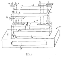
- a flexible spring 20 ( Figure 6) is attached to an arm 22 and to a load beam 24.
- the spring 20 is formed with two legs 26 and 28 and a connecting portion 30, and is generally C-shaped, or in an open rectangular form.
- the flexible spring may be made from a thin, flat stainless steel and is joined, by spot welding for example, at its connecting portion 30 to the top surface of the load beam 24.
- the ends of the legs 26 and 28 of the spring 20 are connected to the adjacent surface 32 of the arm 22, by clamping screws 34, by way of example.
- Apertured spacers 50 which accommodate the screws 34 are provided between the surface 32 of the arm 22 and legs 26, 28 of the spring 20.
- the arm 22 is configured as a hollow box, made of relatively light material such as aluminum.
- the arm 22 may be connected to an actuator 23, ( Figure 5) such as a voice coil motor, for accessing different data tracks, or may be stationary and supporting a fixed head relative to an associated data track.
- the arm 22 has a recess 36 formed in the surface 32 into which the load beam 24 is seated.
- the load beam is formed in a box-like configuration, and is made of stainless steel, for example.
- the geometry of the load beam is such that clearance is minimal between the walls of the box-like beam and the walls of the arm recess, thereby minimizing air leakage, yet allowing the beam to move up and down relative to the depth of the recess 36.
- the head mounting assembly shown in Figures 3 and 4 permits go-and-return movement of the head towards and away from a magnetic record.
- the arm 22 and beam 24 provide relatively movable rigid structural parts interconnected through the spring device 20.
- the beam 24 is a sliding fit in the guide passage provided by the aperture entrance in the wall of the arm 22 leading to recess 36. The close fit causes the beam 24 to slide linearly in the manner of a piston in a cylinder and prevents rotation of the beam in the plane of the aperture entrance.
- the head mounting assembly of Figures 3 and 4 minimise undesirable radial, circumferential and yaw motion of the head.
- the arm 22 has a slot or second aperture 38 formed in its side, which allows air to be drawn into the interior of the hollow arm when an adjacent disc 40 is rotating.
- the air entering the slot 38 provides an aerodynamic force for loading the beam towards the surface of the rotating disc 40.
- Flexures 42a, b are attached to each end of the load beam 24, by spot welding for example, to form cantilevered arms.
- Each of the flexures 42 has a dimple or button-like protuberance 44 that contacts the flat top of respective raised pedestals 46 disposed on the surface of the load beam.
- the dimple 44 and pedestal 46 form a pivot point for the flexure to allow pitch and roll to occur while the head is following the variations in the disc surface.
- Air bearing head sliders 48 (only one shown in Figure 6) are bonded to the center of each flexure 42a, b. Each slider supports a magnetic transducer having a transducing gap at the air bearing surface of the slider for transducing action with the rotating magnetic disc.
- a force applied transversely to the length of the load beam and spring will cause the load beam to move in the direction of the force without any rotational effects.
- the structures including the flexures and heads on either side of the centerline will move together, towards and away from a rotating disk, in a plane that is substantially parallel to the plane of the rotating disc, surface facing the heads.
- the force for moving the load beam and heads to the disc may be the air pressure generated by the rotating disc and transmitted through the arm slot and applied to the load beam; or a mechanically applied force.
Landscapes
- Supporting Of Heads In Record-Carrier Devices (AREA)
Claims (9)
daß ein zweites Trägerelement (Fig. 5) im anderen Ende der durchgehenden Ausnehmung bzw. -öffnung, wie in der vorbeschriebenen Weise gleitet, und
daß ein zweiter freitragender Arm und Befestigungsblock durch das zweite Trägerelement getragen wird, wodurch zwei Köpfe, die auf entgegengesetzte Seiten eines Aufzeichnungsmediums arbeiten, montiert werden können.
Applications Claiming Priority (2)
| Application Number | Priority Date | Filing Date | Title |
|---|---|---|---|
| US36614 | 1979-05-07 | ||
| US06/036,614 US4268879A (en) | 1979-05-07 | 1979-05-07 | Suspension for air bearing head arm assembly |
Publications (2)
| Publication Number | Publication Date |
|---|---|
| EP0019083A1 EP0019083A1 (de) | 1980-11-26 |
| EP0019083B1 true EP0019083B1 (de) | 1983-06-15 |
Family
ID=21889612
Family Applications (1)
| Application Number | Title | Priority Date | Filing Date |
|---|---|---|---|
| EP80101916A Expired EP0019083B1 (de) | 1979-05-07 | 1980-04-10 | Magnetkopf-Befestigungsvorrichtung |
Country Status (5)
| Country | Link |
|---|---|
| US (1) | US4268879A (de) |
| EP (1) | EP0019083B1 (de) |
| JP (1) | JPS5823664B2 (de) |
| CA (1) | CA1147854A (de) |
| DE (1) | DE3063740D1 (de) |
Families Citing this family (13)
| Publication number | Priority date | Publication date | Assignee | Title |
|---|---|---|---|---|
| FR2475267A1 (fr) * | 1980-01-31 | 1981-08-07 | Cii Honeywell Bull | Plate-forme contenant au moins un transducteur de lecture et/ou d'enregistrement d'un support d'informations |
| US4399476A (en) * | 1981-04-13 | 1983-08-16 | Datapoint Corporation | Suspension assembly for magnetic head |
| US4443824A (en) * | 1981-09-14 | 1984-04-17 | International Business Machines Corporation | Magnetic head arm assembly |
| JPS631886A (ja) * | 1987-03-03 | 1988-01-06 | 川崎重工業株式会社 | 端部前処理溶接ユニツト二重管構造 |
| JPH0182101U (de) * | 1987-11-24 | 1989-06-01 | ||
| US4855851A (en) * | 1988-03-02 | 1989-08-08 | Magnetic Peripherals Inc. | Head suspension for magnetic recording |
| US5065268A (en) * | 1989-12-22 | 1991-11-12 | Seagate Technology, Inc. | Load beam having an additional bend in a head-gimbal assembly |
| US5461525A (en) * | 1990-09-14 | 1995-10-24 | Hutchinson Technology Incorporated | Load beam having areas of varying thickness in the spring region formed by varying numbers of lamina |
| EP0548290A4 (en) * | 1990-09-14 | 1993-08-04 | Hutchinson Technology, Inc. | Improved reverse rail head suspension |
| US5912788A (en) * | 1990-11-09 | 1999-06-15 | Hutchinson Technology Inc. | Flexure region for one-piece flexure-load beam structure |
| US5198945A (en) * | 1990-11-09 | 1993-03-30 | Hutchinson Technology Incorporated | Magnetic head suspension |
| US5796554A (en) * | 1997-04-01 | 1998-08-18 | Western Digital Corporation | Load beam assembly with separate spring and hinge functions |
| US7136261B2 (en) * | 2002-06-12 | 2006-11-14 | Seagate Technology Llc | Aerodynamically shaped load beam having reduced windage and reduced off-track PES |
Family Cites Families (15)
| Publication number | Priority date | Publication date | Assignee | Title |
|---|---|---|---|---|
| FR1043503A (fr) * | 1950-10-07 | 1953-11-10 | Loewe Opta Ag | Organe d'enregistrement ou de reproduction du son |
| US3268877A (en) * | 1954-05-26 | 1966-08-23 | Floating magnetic transducing head | |
| DE1042257B (de) * | 1956-04-21 | 1958-10-30 | Bruno Woelke Dipl Ing | Mehrspur-Magnetkopf fuer bandfoermige Magnettontraeger |
| US3368210A (en) * | 1964-12-02 | 1968-02-06 | Burroughs Corp | Mounting device for magnetic transducing head |
| US3405404A (en) * | 1965-10-04 | 1968-10-08 | Sperry Rand Corp | Air bearing magnetic head mounting |
| US3612775A (en) * | 1969-07-16 | 1971-10-12 | Sperry Rand Corp | Magnetic transducing head assembly with head level adjustment |
| US3812535A (en) * | 1972-10-24 | 1974-05-21 | Memorex Corp | Disk recorder arm assembly |
| US3896495A (en) * | 1974-02-25 | 1975-07-22 | Control Data Corp | Mechanically isolated transducer head with spring loaded arm for flying |
| US3936881A (en) * | 1974-07-01 | 1976-02-03 | International Business Machines Corporation | Air damped head suspension |
| US4058843A (en) * | 1975-07-03 | 1977-11-15 | Burroughs Corporation | Head and gimbal assembly |
| FR2341174A1 (fr) * | 1976-02-12 | 1977-09-09 | Sagem | Dispositif de support d'une tete d'impression et/ou de lecture magnetique |
| JPS52145013A (en) * | 1976-05-27 | 1977-12-02 | Nippon Telegr & Teleph Corp <Ntt> | Magnetic disk device |
| US4141049A (en) * | 1977-12-23 | 1979-02-20 | International Business Machines Corporation | Loading mechanism for negative pressure sliders |
| US4167766A (en) * | 1978-06-05 | 1979-09-11 | Ex-Cell-O Corporation | Flexible disk transducer loading and unloading system |
| US4167765A (en) * | 1978-07-27 | 1979-09-11 | International Business Machines Corporation | Transducer suspension mount apparatus |
-
1979
- 1979-05-07 US US06/036,614 patent/US4268879A/en not_active Expired - Lifetime
-
1980
- 1980-02-08 JP JP55013758A patent/JPS5823664B2/ja not_active Expired
- 1980-03-17 CA CA000347836A patent/CA1147854A/en not_active Expired
- 1980-04-10 EP EP80101916A patent/EP0019083B1/de not_active Expired
- 1980-04-10 DE DE8080101916T patent/DE3063740D1/de not_active Expired
Also Published As
| Publication number | Publication date |
|---|---|
| US4268879A (en) | 1981-05-19 |
| JPS55150157A (en) | 1980-11-21 |
| DE3063740D1 (en) | 1983-07-21 |
| JPS5823664B2 (ja) | 1983-05-17 |
| EP0019083A1 (de) | 1980-11-26 |
| CA1147854A (en) | 1983-06-07 |
Similar Documents
| Publication | Publication Date | Title |
|---|---|---|
| US4408238A (en) | Magnetic head arm assembly | |
| EP0025826A1 (de) | Wandleraufbau mit Tragarm für einen fliegenden Magnetkopf | |
| US3931641A (en) | Transducer suspension mount apparatus | |
| US5184265A (en) | Magnetic head suspension assembly in a disk drive | |
| EP0019083A1 (de) | Magnetkopf-Befestigungsvorrichtung | |
| JPH10507569A (ja) | データ記憶装置用アクチュエータにおける摩擦を低下させる撓み部材 | |
| US4807070A (en) | Supporting structure for dual magnetic head | |
| US5161076A (en) | Magnetic head slider suspension apparatus and method of fabrication | |
| EP0208605B1 (de) | Magnetkopfhaltevorrichtung | |
| JPH0536035A (ja) | 磁気デイスク装置の磁気ヘツド支持装置 | |
| US4783710A (en) | Flexure mount for a disc drive actuator | |
| JP2001076413A (ja) | フレキシブル磁気ディスク用ヘッドスライダー | |
| US4835642A (en) | Magnetic head assembly for double-sided disk drive apparatus | |
| CA2021359C (en) | Magnetic head suspension assembly in a disk drive | |
| US4855851A (en) | Head suspension for magnetic recording | |
| US4943881A (en) | Head supporting structure in disk drive system for double sided flexible disk | |
| US4131924A (en) | Flexure mounted magnetic head positioner for high-speed translation | |
| KR940000890B1 (ko) | 디스크 드라이브의 개량로터리 액튜에이터 | |
| JP3144372B2 (ja) | 磁気ヘッドスライダ支持機構及びこれを備える磁気ディスク装置 | |
| JPH0823976B2 (ja) | 磁気記録再生装置 | |
| JP2841069B2 (ja) | 浮動ヘッドスライダ支持機構 | |
| JP3704042B2 (ja) | 可撓支持緩衝装置 | |
| US4745501A (en) | Thermal isolation of the voice coil motor from base plate and carriage guide rails of a disc drive | |
| JPS62167681A (ja) | 浮動形磁気ヘツド | |
| JP2539075B2 (ja) | 磁気記録再生装置 |
Legal Events
| Date | Code | Title | Description |
|---|---|---|---|
| PUAI | Public reference made under article 153(3) epc to a published international application that has entered the european phase |
Free format text: ORIGINAL CODE: 0009012 |
|
| AK | Designated contracting states |
Designated state(s): DE FR GB IT SE |
|
| 17P | Request for examination filed |
Effective date: 19801216 |
|
| GRAA | (expected) grant |
Free format text: ORIGINAL CODE: 0009210 |
|
| AK | Designated contracting states |
Designated state(s): DE FR GB IT SE |
|
| PG25 | Lapsed in a contracting state [announced via postgrant information from national office to epo] |
Ref country code: IT Free format text: LAPSE BECAUSE OF FAILURE TO SUBMIT A TRANSLATION OF THE DESCRIPTION OR TO PAY THE FEE WITHIN THE PRESCRIBED TIME-LIMIT;WARNING: LAPSES OF ITALIAN PATENTS WITH EFFECTIVE DATE BEFORE 2007 MAY HAVE OCCURRED AT ANY TIME BEFORE 2007. THE CORRECT EFFECTIVE DATE MAY BE DIFFERENT FROM THE ONE RECORDED. Effective date: 19830615 |
|
| REF | Corresponds to: |
Ref document number: 3063740 Country of ref document: DE Date of ref document: 19830721 |
|
| ET | Fr: translation filed | ||
| PLBE | No opposition filed within time limit |
Free format text: ORIGINAL CODE: 0009261 |
|
| STAA | Information on the status of an ep patent application or granted ep patent |
Free format text: STATUS: NO OPPOSITION FILED WITHIN TIME LIMIT |
|
| 26N | No opposition filed | ||
| PGFP | Annual fee paid to national office [announced via postgrant information from national office to epo] |
Ref country code: SE Payment date: 19840630 Year of fee payment: 5 |
|
| PG25 | Lapsed in a contracting state [announced via postgrant information from national office to epo] |
Ref country code: SE Effective date: 19850411 |
|
| PGFP | Annual fee paid to national office [announced via postgrant information from national office to epo] |
Ref country code: FR Payment date: 19900328 Year of fee payment: 11 |
|
| PGFP | Annual fee paid to national office [announced via postgrant information from national office to epo] |
Ref country code: GB Payment date: 19900331 Year of fee payment: 11 |
|
| PGFP | Annual fee paid to national office [announced via postgrant information from national office to epo] |
Ref country code: DE Payment date: 19900427 Year of fee payment: 11 |
|
| PG25 | Lapsed in a contracting state [announced via postgrant information from national office to epo] |
Ref country code: GB Effective date: 19910410 |
|
| GBPC | Gb: european patent ceased through non-payment of renewal fee | ||
| PG25 | Lapsed in a contracting state [announced via postgrant information from national office to epo] |
Ref country code: FR Effective date: 19911230 |
|
| PG25 | Lapsed in a contracting state [announced via postgrant information from national office to epo] |
Ref country code: DE Effective date: 19920201 |
|
| REG | Reference to a national code |
Ref country code: FR Ref legal event code: ST |
|
| EUG | Se: european patent has lapsed |
Ref document number: 80101916.7 Effective date: 19860128 |