EP0019101A1 - Installation pour le traitement au mouillé de matières textiles en boyau - Google Patents
Installation pour le traitement au mouillé de matières textiles en boyau Download PDFInfo
- Publication number
- EP0019101A1 EP0019101A1 EP80102123A EP80102123A EP0019101A1 EP 0019101 A1 EP0019101 A1 EP 0019101A1 EP 80102123 A EP80102123 A EP 80102123A EP 80102123 A EP80102123 A EP 80102123A EP 0019101 A1 EP0019101 A1 EP 0019101A1
- Authority
- EP
- European Patent Office
- Prior art keywords
- nozzle
- textile material
- strand
- sensor element
- air
- Prior art date
- Legal status (The legal status is an assumption and is not a legal conclusion. Google has not performed a legal analysis and makes no representation as to the accuracy of the status listed.)
- Granted
Links
- 239000004753 textile Substances 0.000 title claims abstract description 86
- 239000000463 material Substances 0.000 title claims abstract description 74
- 230000000694 effects Effects 0.000 claims description 2
- 238000009434 installation Methods 0.000 claims 1
- 238000007664 blowing Methods 0.000 abstract description 5
- 238000013461 design Methods 0.000 description 4
- 230000000284 resting effect Effects 0.000 description 2
- 230000000717 retained effect Effects 0.000 description 2
- 238000000926 separation method Methods 0.000 description 2
- 230000007547 defect Effects 0.000 description 1
- 238000004043 dyeing Methods 0.000 description 1
- 238000002474 experimental method Methods 0.000 description 1
- 230000002349 favourable effect Effects 0.000 description 1
- 238000003780 insertion Methods 0.000 description 1
- 230000037431 insertion Effects 0.000 description 1
- 230000007257 malfunction Effects 0.000 description 1
- 239000002184 metal Substances 0.000 description 1
- 238000012986 modification Methods 0.000 description 1
- 230000004048 modification Effects 0.000 description 1
- 238000012360 testing method Methods 0.000 description 1
- 238000012549 training Methods 0.000 description 1
- 238000005406 washing Methods 0.000 description 1
Images


Classifications
-
- D—TEXTILES; PAPER
- D06—TREATMENT OF TEXTILES OR THE LIKE; LAUNDERING; FLEXIBLE MATERIALS NOT OTHERWISE PROVIDED FOR
- D06B—TREATING TEXTILE MATERIALS USING LIQUIDS, GASES OR VAPOURS
- D06B3/00—Passing of textile materials through liquids, gases or vapours to effect treatment, e.g. washing, dyeing, bleaching, sizing, impregnating
- D06B3/24—Passing of textile materials through liquids, gases or vapours to effect treatment, e.g. washing, dyeing, bleaching, sizing, impregnating of fabrics in roped form
- D06B3/26—Passing of textile materials through liquids, gases or vapours to effect treatment, e.g. washing, dyeing, bleaching, sizing, impregnating of fabrics in roped form in superimposed, i.e. stack-packed, form
Definitions
- the invention relates to a device for the wet treatment of strand-like textile material, comprising at least one nozzle for supplying an air flow to the textile material and devices for retaining an air bubble formed in the strand-like material, for sensing this air bubble and for controlling the air supply.
- the invention is therefore based on the object, while avoiding these defects, to design a device of the type mentioned in such a way that absolutely reliable, trouble-free operation is achieved with simple constructional means.
- a separate scanning device which contains a sensor element resting on the side of the air bubble facing away from the nozzle.
- the scanning device is arranged in the direction of movement of the textile goods in front of the device which retains the air bubble.
- the spatial separation enables the selection of an optimal position of the scanning device for the scanning function. It is also advantageous that the scanning device can be made relatively light, since it does not have to retain the air bubble at the same time, as in the known prior art described at the outset.
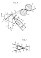
- strand-like textile material 1 is wet treated, e.g. rinsed or washed, and transported in the direction of arrows 2.
- At least one nozzle 3 for the supply of an air flow is provided in the part of the wet treatment device which is of particular interest here. 1 shows only one nozzle 3 with the parts assigned to it, depending on the width of the textile material or the number of adjacent textile material strands, several such - similar - nozzles can also be provided, which - as seen perpendicular to the plane of the drawing in FIG. 1 - lie one behind the other .
- the nozzle 3 is provided with an outwardly widening mouthpiece 5, which guides the textile material 1 close to the nozzle opening 6.
- This mouthpiece is - as can be seen above all from FIG. 2 - essentially formed by two V-shaped guide plates 5a, 5b which form guide surfaces for the textile material 1 on their inner sides and from the nozzle opening 6 in the direction of the The nozzle of the emerging air flow (arrows 4) diverge.
- the guide plates can be essentially flat (see FIG. 2) and can be made of sheet metal or suitable plastic plates, for example.
- the mouthpiece 5 is fastened in a suitable manner in the area of the nozzle opening 6 to the nozzle 3 in such a way that the textile material strand to be blown is in any case directed past the nozzle opening 6 (in the area of the narrowest point of the V-shape) between the two guide plates 5a, 5b becomes.
- the size of the guide plates 5a, 5b of the mouthpiece 5 should be said that this one On the one hand, they should be sufficiently wide to be able to guide the textile material 1 sufficiently in front of and behind the nozzle opening 6, and on the other hand they should have a sufficient length (in the direction of the air flow emerging from the nozzle 3 according to arrow 4) so that they are particularly large inflated strand of textile goods can still grasp this laterally.
- the edges of the guide plates 5a, 5b directed opposite the textile material transport direction (arrow 2) are rounded or flanged so that a gentle insertion of the textile material 1 into the mouthpiece 5 is ensured.
- the nozzle 3 is arranged to blow obliquely upwards, while the strand-like textile material 1 is transported approximately vertically or approximately vertically upwards from a wet treatment bath (not shown) (arrow 2) in such a way that the textile material 1 always rests on the nozzle opening 6 due to its own weight.
- the textile material 1 is conveyed continuously upwards after passing through the nozzle opening 6 and the mouthpiece 5.
- a device for retaining an air bubble 10 formed in the textile material is provided behind the nozzle 3.
- the above-mentioned restraint device is formed by two deflecting rollers 8, 9, which in this case are arranged approximately obliquely one behind the other and are successively passed through by the textile goods 1 transported in the direction of arrow 2.
- the first passed through the textile material 1 deflection roller 8 ensures that the textile material 1 that runs onto it is compressed by the first deflection so that the area between this deflection roller 8 and mouthpiece 5 or Nozzle 3 existing air bubble 10 cannot migrate beyond these deflecting rollers.
- a throttle valve 11 which is provided as a control element, is installed inside the nozzle 3 and can be adjusted between a fully open and a completely closed position.
- this throttle valve 11 is set as a function of the pivoting position of a control bracket 12 which is articulated on the side of the textile material strand opposite the nozzle opening 6 and can be pivoted by the air bubble 10 formed in the textile material 1.
- this control bracket 12 is carried by the mouthpiece 5 at its end pointing in the transport direction (arrow 2) of the textile material 1 via an articulated axis 13.
- the control lever 12 can then be pivoted about its hinge axis 13 in the direction of the double arrow 14 by always resting on the said side of the textile material 1 and thereby scanning the size of the air bubble 10.
- the control bracket 12 is connected to the throttle valve 11, in particular to its pivot axis 11a, via a hinge point 15 and a connecting linkage 16 (cf. FIG. 1).
- This connection between the throttle valve 11 and the control bracket 12 should allow control in such a way that this control bracket 12 can cause the throttle valve 11 to close even with a small deflection, but at the same time it must be ensured that a further deflection of the control bracket 12 by a Free stroke of this bracket is possible so that this control bracket 12 in no way hinders the transport movement of the strand-like textile material 1.
- the supply of air it is preferred to supply it to the nozzle 3 from the interior of the wet treatment container, for example the interior of the runner.
- the nozzle 3 is at one end of an air supply line Pipe 17 grown, in which a fan 18, for example designed as an axial fan, is arranged, which generates the air flow 4 for blowing the textile material 1.
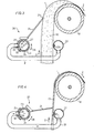
- the scanning device for the air bubble contains a control bracket 12 which is in control connection with the air supply throttle valve 11 via a connecting rod 16, the scanning device with the associated control elements can also be designed differently, as the following examples show.
- the separate scanning device 20 contains a sensor element in the form of a closed control bracket 21, on which the side of the air bubble 10 or the textile material 1 that is remote from the air nozzle 22 rests.
- the control bracket 21 is carried by a tubular control body 23 to which it is connected in a rotationally fixed manner.
- This tubular control body 23 surrounds an air supply pipe 24 relatively closely, but rotatably on a short longitudinal section of the air supply pipe 24 (see FIG. 5).
- the control body 23 is fixed in its axial position by an arcuate pipe connection element 25 encompassing it, the pipe connection element 25 being welded onto the air supply pipe 24.
- the rotational mobility of the control body 23 in the direction of the double arrow 26 is limited by a guide slot 27 provided in the air supply pipe 24, into which a stop pin 28 engages in a rotationally fixed manner with the control body 23.
- an opening 29 is provided in the air supply pipe 24, which is opposite an opening 30 of the same size in the pipe connection element 25, to which a connecting pipe 31 to the nozzle 22 is connected.
- the air supply pipe 24 with the control body 23 arranged thereon is also located on the side of the textile material 1 facing away from the nozzle 22; the connecting pipe 31 between the air supply pipe 24 and the nozzle 22 must therefore be guided so that it does not hinder the movement of the textile material strand.
- this nozzle 22 can be designed in the form of a nozzle tube extending over the entire working width of the wet treatment device, i.e. perpendicular to the plane of the drawing in FIGS. 3 and 4, which preferably has a number of over its length individual nozzle openings 22a (Fig. 3), but possibly also has a continuous nozzle slot.
- control bracket 21 (viewed in the direction of the working width, parallel to the nozzle 22) will generally depend on the size or width of the textile material 1 to be treated. In the embodiment of the scanning device 20 shown in FIG. 5, the control bracket 21 is designed to be correspondingly narrow for relatively narrow strands of textile material.
- FIG. 6, shows an embodiment variant in which the scanning device 20 'is proportional broad textile or relatively wide strands of textile goods is determined.
- the control bracket 21 'therefore also has a relatively large width, and therefore two control bodies 23' are also arranged on the air supply pipe 24 with a corresponding axial distance in the same manner as described and illustrated with reference to FIGS. 3 and 4.
- the control bracket 21 ' is in this case rotatably arranged with two control bodies 23' on the same air supply line 24.
- a connecting pipe 31' is connected to the same air supply pipe 24 in the same way as in the case of FIGS. 3 and 4, both connecting pipes 31 'having approximately the same length - between the air supply pipe 24 and the nozzle pipe 22' .
- These two connecting tubes 31 ' are then guided to the nozzle tube 22' on both sides of the strand cross section of the textile material.
- a further modification of the embodiment variants of the separate scanning device described with reference to FIGS. 5 and 6 can be achieved in that when using two control bodies with these two control bodies either a common broad sensor element (corresponding to FIG. 6) or a narrow sensor element ( 5) can be connected, for example, so that the wet treatment device can be used for an alternative treatment of broadly or narrowly guided strand-like textile goods.
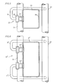
- a structurally particularly simple embodiment means the third exemplary embodiment of the device illustrated in FIGS. 7 to 9.
- the preferably strand-like textile material 1 is first transported in a manner similar to that in the previous exemplary embodiments - in the direction of the arrows 2 - from the bottom upwards and is guided around at least one deflecting roller 8 which is intended to retain an air bubble 10 to be formed in the textile material 1 is.
- a nozzle tube 35 which supplies the air is arranged.
- the nozzle tube 35 extends - perpendicular to the plane of the drawing in FIGS. 7 and 8 - approximately over the entire working width of the wet treatment device and can have one or more through openings 36 (if necessary, however, at least one through slot is also possible).
- the separately arranged scanning device 37 for the air bubble 10 or the textile material 1 also contains a pivotable sensor element in the form of a control bracket 38, which - in a manner similar to the second exemplary embodiment according to FIGS. 3 to 6 - with at least one Air supply to the nozzle determining nozzle body 39 is rotatably connected.
- the pivot axis of the control bracket 38 which in turn coincides with the longitudinal axis 40 of the nozzle tube 35, is arranged on the same side of the strand-like textile material 1 as the nozzle or the nozzle tube 35.
- the control bracket 38 encloses the strand-like textile material 1 at least on three sides. As shown in FIG.
- this control bracket 38 can, however, preferably be designed in the form of a completely closed bracket and in this case have an adjustable web 42 which delimits the strand cross section 1 a on the one side (on the fourth side) and extends over the entire width of the control bracket 38 is sufficient and - as indicated by dashed lines - can be inserted in various positions (for example through opposite bores in the side struts 38a of the control bracket 38).
- a single control body 39 is sufficient for a control bracket 38, which can extend approximately over the width of a strand of textile material (cf. FIG. 9).
- the control body 39 is in turn tubular and encompasses the nozzle tube 35 relatively narrowly, although it can be rotated to a limited extent in the direction of the double arrow 41 and at its ends by limit pieces (not shown) - similar Lich as in the second embodiment according to FIGS. 3 to 6 - is fixed in its axial position.
- a counterweight 43 for the control bracket 38 is expediently arranged on the control body 39, as shown in FIGS. 7 and 8, in such a way that the latter, in addition to its frictional entrainment by the textile material 1, also against the side of the textile material facing away from the nozzle tube 35 can be held. This counterweight may also be adjustable in its force effect.
- control body 39 has at least one nozzle opening 44 in its circumferential area in contact with one side of the textile material 1, which, depending on the pivoting position of the control bracket 38 and thus of the control body 39 (pivoting direction according to double arrow 41) the corresponding through openings 36 in the nozzle tube 35 can be covered or, in contrast, can be completely displaced. In this way, the air supply through the nozzle tube 35 and its through openings 36 can be released or completely blocked, intermediate positions also being possible, of course.
- control bracket 38 and control body 39 can be limited by a stop pin 45 which engages with a correspondingly long guide slot 46, the stop pin 45 being fastened in the fixed nozzle tube and the guide slot 46 is arranged in the control body 39 (a reverse arrangement is also conceivable).
- a wet treatment device as described above with the aid of the various exemplary embodiments, can be constructed in such a way that it is intended for the wet treatment of a single, circular and endlessly sewn together strand of textile, or it can also be used for a plurality of endlessly made strands of textile running in parallel or can also be constructed for an endlessly sewn together and spirally passed textile strand several times through the treatment bath.
- a number of separate scanning devices with nozzles corresponding to the number of strand sections running next to one another can be arranged next to one another with a corresponding distance.
- the wet treatment device can be used for both continuous and discontinuous treatment.
Landscapes
- Engineering & Computer Science (AREA)
- Textile Engineering (AREA)
- Treatment Of Fiber Materials (AREA)
Applications Claiming Priority (2)
| Application Number | Priority Date | Filing Date | Title |
|---|---|---|---|
| DE2918695 | 1979-05-09 | ||
| DE19792918695 DE2918695A1 (de) | 1979-05-09 | 1979-05-09 | Vorrichtung zur nassbehandlung von strangfoermigem textilgut |
Publications (2)
| Publication Number | Publication Date |
|---|---|
| EP0019101A1 true EP0019101A1 (fr) | 1980-11-26 |
| EP0019101B1 EP0019101B1 (fr) | 1984-09-12 |
Family
ID=6070316
Family Applications (1)
| Application Number | Title | Priority Date | Filing Date |
|---|---|---|---|
| EP80102123A Expired EP0019101B1 (fr) | 1979-05-09 | 1980-04-19 | Installation pour le traitement au mouillé de matières textiles en boyau |
Country Status (4)
| Country | Link |
|---|---|
| US (1) | US4318209A (fr) |
| EP (1) | EP0019101B1 (fr) |
| JP (1) | JPS5928654B2 (fr) |
| DE (2) | DE2918695A1 (fr) |
Cited By (1)
| Publication number | Priority date | Publication date | Assignee | Title |
|---|---|---|---|---|
| FR2595726A1 (fr) * | 1986-03-14 | 1987-09-18 | Abs Sobrinho Jose | Machine de nettoyage et/ou de blanchiment et/ou de lavage et/ou de teinture notamment pour tissu a mailles |
Families Citing this family (10)
| Publication number | Priority date | Publication date | Assignee | Title |
|---|---|---|---|---|
| IT1135149B (it) * | 1981-01-23 | 1986-08-20 | Attilio Bertoldi | Macchina per la follatura,lavaggio e pre-asciugatura di tessuti in corda |
| DE3200373C2 (de) * | 1982-01-08 | 1985-09-26 | Brückner-Apparatebau GmbH, 6120 Erbach | Verfahren und Vorrichtung zum Verlegen von strangförmigem Textilgut |
| JPS5966044A (ja) * | 1982-10-06 | 1984-04-14 | Hitachi Ltd | 電子線偏向器 |
| JPS6147047A (ja) * | 1984-08-13 | 1986-03-07 | Jeol Ltd | 試料結晶性組織の分析方法 |
| DE3433701A1 (de) * | 1984-09-13 | 1986-03-20 | Brückner-Apparatebau GmbH, 6120 Erbach | Verfahren und vorrichtung zum dehnen von schlauchware |
| DE3600558A1 (de) * | 1986-01-10 | 1987-07-16 | Brueckner Apparatebau Gmbh | Vorrichtung zum aufblasen einer schlauchfoermigen warenbahn |
| JPS63150062U (fr) * | 1987-03-23 | 1988-10-03 | ||
| DE3742597A1 (de) * | 1987-12-16 | 1989-06-29 | Brueckner Apparatebau Gmbh | Verfahren und vorrichtung zur diskontinuierlichen nassbehandlung von gestricktem oder gewirktem textilgut |
| DE3929599A1 (de) * | 1989-09-06 | 1991-03-07 | Dornier Gmbh Lindauer | Rundbreithalter fuer textile schlauchware |
| US9416474B2 (en) * | 2013-04-12 | 2016-08-16 | Teresa Catallo | Washer for tubular knitted fabric material |
Citations (5)
| Publication number | Priority date | Publication date | Assignee | Title |
|---|---|---|---|---|
| FR1583849A (fr) * | 1967-05-10 | 1969-12-05 | ||
| DE1460259B1 (de) * | 1964-12-08 | 1970-03-26 | Inst Fuer Textiltechnologie | Haspelkufe zum Färben von schlauchf¦rmigen Textilgut |
| FR2193333A6 (fr) * | 1972-07-13 | 1974-02-15 | Leemetals Ltd | |
| US3837801A (en) * | 1972-03-21 | 1974-09-24 | Woodside Constr Corp | Method and apparatus for processing fabrics in rope-like form |
| US3958432A (en) * | 1974-02-25 | 1976-05-25 | Aronoff Edward Israel | Apparatus for treating tubular fabrics |
Family Cites Families (1)
| Publication number | Priority date | Publication date | Assignee | Title |
|---|---|---|---|---|
| GB1230477A (fr) * | 1968-11-20 | 1971-05-05 |
-
1979
- 1979-05-09 DE DE19792918695 patent/DE2918695A1/de not_active Withdrawn
-
1980
- 1980-04-16 US US06/141,137 patent/US4318209A/en not_active Expired - Lifetime
- 1980-04-19 DE DE8080102123T patent/DE3069130D1/de not_active Expired
- 1980-04-19 EP EP80102123A patent/EP0019101B1/fr not_active Expired
- 1980-05-09 JP JP55061628A patent/JPS5928654B2/ja not_active Expired
Patent Citations (6)
| Publication number | Priority date | Publication date | Assignee | Title |
|---|---|---|---|---|
| DE1460259B1 (de) * | 1964-12-08 | 1970-03-26 | Inst Fuer Textiltechnologie | Haspelkufe zum Färben von schlauchf¦rmigen Textilgut |
| FR1583849A (fr) * | 1967-05-10 | 1969-12-05 | ||
| DE1760268A1 (de) * | 1967-05-10 | 1972-02-10 | Nyman Curt Lennart | Verfahren und Vorrichtung zum Aufnehmen aus einem Zurichtungsbad,zum Normalisieren und maschengerechten Ordnen von Trikotgewebeschlaeuchen od.dgl. |
| US3837801A (en) * | 1972-03-21 | 1974-09-24 | Woodside Constr Corp | Method and apparatus for processing fabrics in rope-like form |
| FR2193333A6 (fr) * | 1972-07-13 | 1974-02-15 | Leemetals Ltd | |
| US3958432A (en) * | 1974-02-25 | 1976-05-25 | Aronoff Edward Israel | Apparatus for treating tubular fabrics |
Cited By (1)
| Publication number | Priority date | Publication date | Assignee | Title |
|---|---|---|---|---|
| FR2595726A1 (fr) * | 1986-03-14 | 1987-09-18 | Abs Sobrinho Jose | Machine de nettoyage et/ou de blanchiment et/ou de lavage et/ou de teinture notamment pour tissu a mailles |
Also Published As
| Publication number | Publication date |
|---|---|
| DE3069130D1 (en) | 1984-10-18 |
| JPS5620663A (en) | 1981-02-26 |
| US4318209A (en) | 1982-03-09 |
| JPS5928654B2 (ja) | 1984-07-14 |
| DE2918695A1 (de) | 1980-11-13 |
| EP0019101B1 (fr) | 1984-09-12 |
Similar Documents
| Publication | Publication Date | Title |
|---|---|---|
| DE3214396C2 (de) | Vorrichtung zum Aufwickeln einer Bahn, wie Papierbahn | |
| CH643612A5 (de) | Vorrichtung zum schusseintrag an einer schuetzenlosen webmaschine. | |
| DE69116672T2 (de) | Vorrichtung zum Strecken eines Schussfadens in einer Webmaschine | |
| EP0019101B1 (fr) | Installation pour le traitement au mouillé de matières textiles en boyau | |
| EP0318802B1 (fr) | Système d'insertion de la trame pour machines à tisser pneumatiques avec au moins deux tuyères réunies en faisceau | |
| DE1617959A1 (de) | Verfahren und Vorrichtung zur aseptischen Entfernung von Fluessigkeit von einem bahnfoermigen Verpackungsmaterial | |
| EP0879907B1 (fr) | Machine de texturation | |
| EP0023929A1 (fr) | Buses pour métier à tisser à jet de fluide | |
| DE3819426C2 (fr) | ||
| DE3833969A1 (de) | Garnzufuhreinrichtung | |
| EP0527355A1 (fr) | Procédé et dispositif pour l'introduction pneumatique d'une mèche de fibres dans un métier à filer | |
| DE19531987C2 (de) | Fadeneinfädeleinrichtung an einer Strecktexturiermaschine | |
| CH621371A5 (fr) | ||
| CH656650A5 (de) | Vorrichtung zum abziehen eines fadens von einer spinnstelle. | |
| CH625189A5 (en) | Thread feeler device for automatic cone-winders | |
| AT410328B (de) | Anordnung zum einfädeln in einen kalander | |
| DE2713624B2 (de) | Vorrichtung zum selbsttätigen Einfädeln eines Fadens in einen Läufer | |
| DE1899360U (de) | Streckwerk fuer spinnmaschinen. | |
| DE2919254C2 (de) | Faltmaschine für Wäschestücke | |
| DE1710119C3 (de) | Vorrichtung zum Erfassen des Fadenanfanges eines Kopses mittels einer Saugdüse | |
| EP0058227B1 (fr) | Rameuse pour bandes textiles | |
| CH669803A5 (de) | Vorrichtung an einer duesenwebmaschine zum speichern eines einzutragenden schussfadens. | |
| DE19524187B4 (de) | Stofflegemaschine mit einem Legewagen | |
| DE8111908U1 (de) | Vorrichtung zur heissluft-trocknung einer warenbahn | |
| DE19527994C1 (de) | Angelrolle mit einer Schnurführungsrollenanordnung |
Legal Events
| Date | Code | Title | Description |
|---|---|---|---|
| PUAI | Public reference made under article 153(3) epc to a published international application that has entered the european phase |
Free format text: ORIGINAL CODE: 0009012 |
|
| AK | Designated contracting states |
Designated state(s): CH DE FR GB IT |
|
| 17P | Request for examination filed |
Effective date: 19810331 |
|
| ITF | It: translation for a ep patent filed | ||
| GRAA | (expected) grant |
Free format text: ORIGINAL CODE: 0009210 |
|
| AK | Designated contracting states |
Designated state(s): CH DE FR GB IT LI |
|
| REF | Corresponds to: |
Ref document number: 3069130 Country of ref document: DE Date of ref document: 19841018 |
|
| ET | Fr: translation filed | ||
| PLBE | No opposition filed within time limit |
Free format text: ORIGINAL CODE: 0009261 |
|
| STAA | Information on the status of an ep patent application or granted ep patent |
Free format text: STATUS: NO OPPOSITION FILED WITHIN TIME LIMIT |
|
| 26N | No opposition filed | ||
| ITTA | It: last paid annual fee | ||
| PGFP | Annual fee paid to national office [announced via postgrant information from national office to epo] |
Ref country code: FR Payment date: 19970307 Year of fee payment: 18 |
|
| PGFP | Annual fee paid to national office [announced via postgrant information from national office to epo] |
Ref country code: GB Payment date: 19970319 Year of fee payment: 18 |
|
| PGFP | Annual fee paid to national office [announced via postgrant information from national office to epo] |
Ref country code: CH Payment date: 19970324 Year of fee payment: 18 |
|
| PGFP | Annual fee paid to national office [announced via postgrant information from national office to epo] |
Ref country code: DE Payment date: 19970630 Year of fee payment: 18 |
|
| PG25 | Lapsed in a contracting state [announced via postgrant information from national office to epo] |
Ref country code: GB Free format text: LAPSE BECAUSE OF NON-PAYMENT OF DUE FEES Effective date: 19980419 |
|
| PG25 | Lapsed in a contracting state [announced via postgrant information from national office to epo] |
Ref country code: LI Free format text: LAPSE BECAUSE OF NON-PAYMENT OF DUE FEES Effective date: 19980430 Ref country code: FR Free format text: THE PATENT HAS BEEN ANNULLED BY A DECISION OF A NATIONAL AUTHORITY Effective date: 19980430 Ref country code: CH Free format text: LAPSE BECAUSE OF NON-PAYMENT OF DUE FEES Effective date: 19980430 |
|
| GBPC | Gb: european patent ceased through non-payment of renewal fee |
Effective date: 19980419 |
|
| REG | Reference to a national code |
Ref country code: CH Ref legal event code: PL |
|
| PG25 | Lapsed in a contracting state [announced via postgrant information from national office to epo] |
Ref country code: DE Free format text: LAPSE BECAUSE OF NON-PAYMENT OF DUE FEES Effective date: 19990202 |
|
| REG | Reference to a national code |
Ref country code: FR Ref legal event code: ST |