EP0527355A1 - Procédé et dispositif pour l'introduction pneumatique d'une mèche de fibres dans un métier à filer - Google Patents
Procédé et dispositif pour l'introduction pneumatique d'une mèche de fibres dans un métier à filer Download PDFInfo
- Publication number
- EP0527355A1 EP0527355A1 EP92112303A EP92112303A EP0527355A1 EP 0527355 A1 EP0527355 A1 EP 0527355A1 EP 92112303 A EP92112303 A EP 92112303A EP 92112303 A EP92112303 A EP 92112303A EP 0527355 A1 EP0527355 A1 EP 0527355A1
- Authority
- EP
- European Patent Office
- Prior art keywords
- sliver
- injector
- insertion funnel
- spinning machine
- nozzle
- Prior art date
- Legal status (The legal status is an assumption and is not a legal conclusion. Google has not performed a legal analysis and makes no representation as to the accuracy of the status listed.)
- Granted
Links
Images


Classifications
-
- D—TEXTILES; PAPER
- D01—NATURAL OR MAN-MADE THREADS OR FIBRES; SPINNING
- D01H—SPINNING OR TWISTING
- D01H9/00—Arrangements for replacing or removing bobbins, cores, receptacles, or completed packages at paying-out or take-up stations ; Combination of spinning-winding machine
- D01H9/005—Arrangements for replacing or removing bobbins, cores, receptacles, or completed packages at paying-out or take-up stations ; Combination of spinning-winding machine for removing empty packages or cans and replacing by completed (full) packages or cans at paying-out stations; also combined with piecing of the roving
- D01H9/008—Arrangements for replacing or removing bobbins, cores, receptacles, or completed packages at paying-out or take-up stations ; Combination of spinning-winding machine for removing empty packages or cans and replacing by completed (full) packages or cans at paying-out stations; also combined with piecing of the roving for cans
Definitions
- the present invention relates to a method and a device for the pneumatic introduction of sliver into a spinning machine according to the preambles of claims 1 and 7.
- a device and a method are known from EP 0 348 678 A1 with which the fiber sliver is pneumatically introduced into a spinning device.
- the device shown there is provided with a compressor.
- This compressor is provided to be installed in a fixed position at a spinning station and, after being offered with sliver at a tubular sliver suction opening, is acted upon by an air stream which is emitted by a previously docked injector nozzle in such a way that the sliver flows or is conveyed in the direction of the narrowest point of the compressor shall be.
- a disadvantage of this known device is that a relatively low suction force acts on the fiber sliver in the tubular suction opening due to the required cross sections.
- the air pressure acting on the sliver clogs the compressor by the sliver and thus does not always ensure that the sliver exits the compressor to the extent that it is there seized by other devices will and can be further promoted.
- the object of the present invention is now to overcome the disadvantages described above and to provide a method and an apparatus which make it possible to make the feeding of sliver into a spinning machine simple and safe.
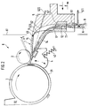
- FIG. 1 schematically shows a section of an open-end spinning device with an insertion funnel 1, a feed roller 2, a feed trough 4 and an opening roller 3 attached to it, which is located in an opening roller housing 31.
- a fiber feed channel 32 connects to the opening roller housing 31 and serves to convey the opened fibers to a spinning element, not shown, for example a rotor or a friction spinning device. Since these are well-known open-end spinning devices, a more detailed description is omitted here.
- the insertion funnel 1 is positively arranged in the feed trough 4, which can be moved concentrically about the axis of the opening roller, for example with a clip or dovetail closure. This connection can be made detachable.
- the feed trough 4 is pressed by a spring 42, on the one hand, against the outer wall of an opening roller housing 31 and, on the other hand, against the feed roller 2.
- the sliver 9 is passed through a channel 12 of the loop catcher 11 and then guided to the introduction funnel 1.
- the loop catcher 11 serves primarily to separate adhering second loops from the sliver 9, which is conveyed out of a sliver can, so that only the correct sliver cross-section can enter the spinning station.
- the cross section of the channel 12 is usually round-oval.
- the loop catcher 11 itself can be designed to be removable from the inlet funnel 1 and is expediently clipped into the foot part 13 of the inlet funnel 1 by means of a clip.
- the inlet funnel 1 has two walls 14 and 15, shown here in section, approaching in the direction of the clamping point of the feeding device, the greatest approximation of which is at a narrow point 16 which is closest to the clamping line of the clamping elements 2 and 4.
- the spring 42 which presses the feed trough 4 against the feed roller 2 and the opening roller housing 31, is supported in the housing of the spinning station. Only one spring 42 is shown in this example. Of course, several springs with different points of attack can also be provided. It is also possible to move the feed roller around a pivot point that is not in the axis of rotation of the opening roller.
- Figure 2 essentially shows the device described in Figure 1, but here is an injector 5, which is provided on the contact surface with the inlet funnel 1 with a seal, is placed on the inlet funnel 1 and is already moving in such a way that inlet funnel 1 and the associated one now move Feed trough 4 from the feed roller Have removed 2 so that the clamping line between these two clamping elements is open.
- the injector 5 was moved into this position by a movement in the direction of the arrow Z and placed on the insertion funnel 1.
- the feed trough 4 is pressed down and the clamping line is thus opened.
- the injector 5 is expediently articulated in such a way that it can follow a small rotational movement of the feed trough 4 without 5 leaks occurring between the insertion funnel 1 and the injector. If, after threading the sliver 9, the injector 5 is moved away from the spinning position in the direction of arrow E, the feed trough 4 and the insertion funnel 1 attached to it move up again due to the spring action of the spring 42. The feed trough 4 then presses the sliver against the stationary feed roller 2.
- the procedure for feeding a sliver 9 to a spinning station is carried out as follows:
- the injector 5 is turned on with a device (not shown), which is, for example, a ground vehicle traveling along the OE spinning machine, an automatic maintenance device arranged on the spinning machine, or another maintenance vehicle guided the spinning station and moved against the insertion funnel 1 in such a way that the feed trough 4 moves away from the feed roller 2.
- the injector 5 must be positioned on the inlet funnel 1, for example using the usual positioning methods that are customary for maintenance machines at spinning positions. Then one of them is not shown Device the injector 5 in the direction of arrow A at its insertion opening the beginning of the sliver 9 presented.
- the sliver channel 8 is formed in that the two parts of the device, insertion funnel 1 and injector 5, close together.
- the sliver 9 passes through the constriction 16, between the feed roller 2 and the feed trough 4, so that the beginning of the sliver is offered to the opening roller 3 for processing.
- a nozzle 51 can be fitted in the lower part of the injector 5.
- the nozzle 52 is expediently arranged such that it emits a flow which acts in the channel 12 of the loop catcher 11 in such a way that there is a slight vortex flow which twists the beginning of the sliver 9 in a manner such as how to end the thread with the fingers twisted together to sharpen it a bit and lead it through a constriction.
- the injector 5 from the insertion funnel 1, or from the spinning unit 6, preferably in the direction of arrow E. Because the injector on its underside in the area of Nozzle 52, pointing to the spinning machine, is open, it can be removed from the spinning position without hindrance without impairing the sliver 9. This recess at the foot of the injector is visible in the dashed line in FIG. 3, which is designated 58.
- FIG. 3 shows a top view of the injector 5, a line labeled 59, which shows the inner wall of the "channel half" of the channel 8, which is formed by joining the parts injector and insertion funnel.
- the symmetrical arrangement of the nozzle channel 522 and the nozzle 52 can also be seen in FIG.
- FIG. 4 shows nozzle channels 522a and 522b, or their nozzles 52a and 52b, the nozzle channels 522a and 522b preferably being aligned such that their lines of action intersect in the constriction 16 of the insertion funnel 1.
- the arrangement of a nozzle channel 511 and the nozzle 51 can also be seen here.
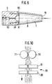
- Figure 5 shows the front view of the injector 5, it being very easy to see in the lower part that a sliver insertion opening 55 is formed such that it extends essentially conically upwards, so that its cross section at the transition point in the loop catcher 11 of the Insertion funnel 1 is approximately as large as the cross section of the channel 12 of the loop catcher.
- a wall 58 will pass into the wall of the channel 12 of the loop catcher 11 and in the further course of the channel 8 into a wall 59 of the injector 5.
- the transitions of the channel parts The insertion opening 55 of the injector 5, the channel 12 and the channel wall 59 should be designed to be as smooth and free of edges as possible so that there is no damage to the sliver 9 when the individual parts of the device are inserted or fly.
- FIG. 6 shows a further advantageous embodiment of the subject matter of the invention.
- An injector 5 is provided here, which has a further nozzle 53 which does not open directly into the sliver channel 8 like the other two nozzles 52 and 51, but into a nozzle channel 177 which is arranged in the upper wall 15 of the insertion funnel 1 and with a nozzle 178, which is located just before the nip between feed roller 2 and feed trough 4, opens.
- This third nozzle 53 is useful, for example, when processing sliver materials which, due to their weight or their friction behavior, cannot be inserted into the introduction funnel 1 so easily.
- the conveying air flow for the sliver 9 is supported in the direction of the clamping point of the spinning device, in that a vacuum is created at the constriction 16 by means of the air flowing through the nozzle 178, which causes the sliver 9 or the beginning of the sliver 9 moves more easily through the constriction 16 to the clamping point or between the clamping elements of the spinning device.
- nozzle in the wall 14 which can be acted upon by the injector 5 with compressed air.
- the feeding of the sliver 9 can also be supported by the fact that the sliver 9 is lifted so far from a device (for example from a spinning can) so that the device according to the invention only lifts the sliver length that is introduced into the spinning station got to.
- a device for example from a spinning can
- the above-described method and the various devices for this are of course applicable to all open-end spinning devices and are not limited to rotor spinning.
- the feed device can be designed, for example, as an apron drafting system.
- the spinning device can be a friction or air spinning device or, more generally, a spinning device that works with an open end or with fibers released.
- This sliver feed can also be used on other sliver processing machines such as Routes are provided, where it is useful to provide a feed device which is capable of further conveying the sliver itself for further processing after the feed device has presented and presented the sliver to the feed device.
- the feed devices for the nozzles 51, 52 and 53 or further arranged nozzles are supplied with compressed air via the feed lines shown.
- the control of the timing of the injector nozzle flows can be individually adjusted depending on the sliver.
- a control is expediently provided here, which it allows the nozzles and their switching sequence to be controlled after the operator has been freely selected.
- the device according to the invention is also expediently integrated into electronically controlled maintenance machines which check for the possible presence of another sliver before a new sliver is attached or before a sliver is introduced into a spinning station.
- a sliver can containing the sliver supply is already present at a spinning station, the sliver end to be inserted hanging out of the can at a certain position or has already been presented to a fixing point at the spinning station by means of a known device.
- a maintenance vehicle can remove an empty sliver can from the respective spinning station, bring a sliver containing sliver to the spinning station and then feed this sliver to the spinning device by means of the device according to the invention.
- the injector 5 or the control device (not shown) of the nozzles of the injector 5 are expediently set such that an injection process takes approximately 1 second. This is advantageous for the sliver, since not too long currents act on the sliver and change or damage it in such a way that it can no longer be conveyed without errors by the feed device.
- the nozzle 178 shown in FIG. 6 can of course also be used in cooperation with the nozzle 53 of the injector 5 to clean a possibly missed clamping point by means of a short air flow pulse before the sliver 9 of the insertion opening 55 for insertion is presented.
- a gripper is advantageously used which has two gripping elements, at least one of which is arranged so as to be movable, that the gripper can be opened and closed again for gripping the sliver.
- the two grippers are designed as rollers which rotate to support the insertion process in such a way that the sliver is conveyed in the direction of the spinning station. The conveying speed and the timing of the running of the rollers are expediently coordinated with the control unit controlling the nozzles.
- Figure 7 shows an injector 5 in longitudinal section.
- the arrangements of the nozzles 51 and 52 and a nozzle 62 are provided.
- Nozzle 51 is directed against the side wall of the sliver insertion opening 55 in such a way that an air vortex is created which twists and / or sharpens the sliver 9. It is thereby achieved that simple threading into the loop catcher 11 of the insertion funnel 1 is possible.
- nozzle 51 is connected to nozzle 62.
- Nozzle 62 supports due to the suction effect of threading the sliver 9 into the insertion funnel 1, which extends into the sliver insertion opening 55, the nozzle 52 can be controlled independently of this and can therefore be pressurized with compressed air after the nozzles 51 and 62. An optimal deflection of the sliver (9) in the direction of the narrow point (16) of the insertion funnel 1 is achieved.
- Rollers 70, 71 are arranged as an additional mechanical tape feed device in the sliver conveying direction directly in front of the injector 5. These rollers 70, 71 grip the fiber sliver 9 and convey it by a rotational movement in the direction of the injector 5. The gripping of the fiber sliver 9 is facilitated by conical ends 701 of the rollers 70, 71. The sliver 9 thus threads itself into the corrugated rolls 70, 71 when it comes into contact with the conical ends 701 of the rotating rolls 70, 71.
- the speed of rotation of the rollers 70, 71 is advantageously such that, compared to the conveying action of the nozzles 51, 52, 62, it slows down the conveyance of the sliver 9 slightly. It is thereby achieved that the sliver 9 is always conveyed in a taut state through the loop catcher 12 or the constriction 16 of the insertion funnel 1. This prevents the sliver 9 from clogging the channels 11, 16 to be traversed and thus would prevent a safe threading into the feeding device.
- the rollers 70, 71 ensure that a defined amount and thus also the weight of the sliver 9 is always conveyed. This is an adjustment of the nozzles 51, 52, 62 with respect to their Flow duration and intensity easier. A safe conveying of the sliver through the channels 11, 16 is thus ensured.
- a seal 63 is arranged on the upper edge of the injector 5. This seal 63 has the effect that a tight connection between injector 5 and inlet funnel 1 can be established. This prevents flow losses from occurring in the channels 8, 11.
- Figure 8 shows a front view of the injector 5 with the rollers 70, 71.
- the nozzle 51 is so inclined to the center line of the injector 5 that it generates an air vortex that prepares the sliver for threading into the narrow points.
- nozzle 51 causes by means of its air jet that the sliver 9 is conveyed in the direction of the nozzle 52.
- the nozzle 52 causes the fiber sliver 9 to be deflected in the direction of the constriction 16 of the insertion funnel 1.
- the fiber sliver 9 is guided at this deflection point through the wall 59 of the injector 5.
- nozzles 60, 61 are arranged on the front of the injector 5.
- the nozzles 60, 61 are also directed in the direction of the constriction 16 of the insertion funnel 1 and cause the sliver to be blown towards the constriction 16. Due to the additional use of the nozzles 60, 61, the flow velocity is maintained despite the changed cross-section, without turbulence or significant flow velocity losses occurring. This is advantageous achieved that the sliver is conveyed towards the narrow point 16 without forming swirls or loops. Clogging of the constriction 16 by the sliver is thus prevented.
- the nozzles 60, 61 ensure safe conveying of the sliver 9 up to the feeding device.
- the rollers 70, 71 rotate in the direction of the injector 5.
- the conveyance of the sliver 9 is mechanically supported by the air nozzles 51, 52, 60, 61.
- the rollers 70, 71 are operated at a speed such that the sliver 9 is always tightened during the pneumatic conveying. This means that the rollers 70, 71 convey more slowly than the air nozzles 51, 52, 60, 61 would do. Clogging of the constrictions by the sliver 9 is thus avoided.
- rollers 70, 71 are advantageously arranged on a maintenance device. Rollers 70, 71 and injector 5 are accordingly only fed to the spinning machine or the spinning station if sliver is to be conveyed through the narrow points and threaded into the spinning machine.
- the maintenance device can either be arranged directly on the spinning machine and can be moved, for example, along a large number of spinning stations, or independently of the individual spinning machine, for example on one or more spinning machines operating automated transport system can be arranged. It has proven to be advantageous to arrange the injector 5 and rollers 70, 71 on a can transporter and thus to introduce the new fiber sliver 9 into the spinning station when the can needs to be replaced at the spinning station.
- roller 70, 71 it is possible that the roller 70, 71 can be removed from one another (70 ') for gripping the fiber sliver 9 and can be brought together again. This ensures a secure and defined gripping of the sliver 9.
- FIG. 9 shows a section through a top view of the injector 5 and the insertion funnel 1.
- the sliver 9 which is deflected along the wall 59 from the injector 5 into the insertion funnel 1, would be swirled strongly without the support of the nozzles 60, 61 when entering the insertion funnel 1 and thus run the risk of narrowing 16 of the insertion funnel 1 to clog.
- the nozzles 60, 61 increase the flow velocity in the larger cross section of the insertion funnel 1 and thereby cause the sliver 9 to be tightened. In addition, they prevent excessive friction of the sliver 9 on the walls of the insertion funnel 1. This also ensures that the sliver is guided safely 9 guaranteed by the constriction 16 of the insertion funnel 1.
- the nozzles 60, 61 are preferably arranged such that they produce an air flow parallel to the side walls of the insertion funnel 1.
- An air cushion is formed which reduces the friction of the sliver 9 on the side walls.
- the nozzles 60, 61 can be dispensed with if the cross-sectional expansion between injector 5 and insertion funnel 1 is not very large. This can be achieved with a given insertion funnel 1 in that 5 side elements are attached to the injector, which are inserted into the channel 8 and thus reduce the cross section. It is also possible to design the injector 5 with its wall 59 or the injector 1 in such a way that there is no major change in cross-section.
- FIG. 10 shows a sliver separating device 80.
- a clamp 81 grips the sliver 9 on the side of the rollers 70, 71 facing the injector 5 and holds the sliver 9 firmly.
- a clamping device 82 also grips the sliver 9 and moves away from the clamping device 81 in the direction of the arrow after the clamping process.
- the sliver 9 is separated between the clamping device 81 and 82.
- the clamping device 81 detaches from the sliver 9. It is thus a defined length of the sliver 9 from the rollers 70, 71 to the beginning of the Sliver 9 made. This defined length ensures that the fiber sliver is securely inserted into the injector 5 or the insertion funnel 1.
- FIG. 11 shows an automatic maintenance machine 90 on a spinning machine 91.
- the automatic maintenance machine 90 runs on a rail along the spinning machine 91. If a fiber sliver 9 is inserted into the spinning station, the automatic walking machine 90 stops at this spinning station. The sliver is gripped and fed to the injector 5, which is arranged on the automatic hiking device 90. The sliver 9 is then inserted into the nip of the spinning station.
Landscapes
- Engineering & Computer Science (AREA)
- Mechanical Engineering (AREA)
- Textile Engineering (AREA)
- Spinning Or Twisting Of Yarns (AREA)
Applications Claiming Priority (4)
| Application Number | Priority Date | Filing Date | Title |
|---|---|---|---|
| DE4126552 | 1991-08-10 | ||
| DE19914126552 DE4126552C2 (de) | 1991-08-10 | 1991-08-10 | Verfahren und Vorrichtung zum pneumatischen Einführen von Faserband in eine OE-Spinnmaschine |
| DE4130510 | 1991-09-13 | ||
| DE19914130510 DE4130510A1 (de) | 1991-09-13 | 1991-09-13 | Verfahren und vorrichtung zum pneumatischen einfuehren von faserband in eine spinnereimaschine |
Publications (2)
| Publication Number | Publication Date |
|---|---|
| EP0527355A1 true EP0527355A1 (fr) | 1993-02-17 |
| EP0527355B1 EP0527355B1 (fr) | 1998-04-01 |
Family
ID=25906261
Family Applications (1)
| Application Number | Title | Priority Date | Filing Date |
|---|---|---|---|
| EP92112303A Expired - Lifetime EP0527355B1 (fr) | 1991-08-10 | 1992-07-18 | Procédé et dispositif pour l'introduction pneumatique d'une mèche de fibres dans un métier à filer |
Country Status (7)
| Country | Link |
|---|---|
| US (1) | US5343686A (fr) |
| EP (1) | EP0527355B1 (fr) |
| JP (1) | JPH05195338A (fr) |
| BR (1) | BR9203046A (fr) |
| CZ (1) | CZ284254B6 (fr) |
| DE (1) | DE59209258D1 (fr) |
| RU (1) | RU2072401C1 (fr) |
Cited By (1)
| Publication number | Priority date | Publication date | Assignee | Title |
|---|---|---|---|---|
| EP3441509B1 (fr) * | 2017-08-11 | 2021-07-21 | Saurer Spinning Solutions GmbH & Co. KG | Dispositif d'alimentation pour un dispositif ouvreur d'un ruban de fibres d'un métier à filer à bout libre |
Families Citing this family (10)
| Publication number | Priority date | Publication date | Assignee | Title |
|---|---|---|---|---|
| CZ29294A3 (en) * | 1994-02-10 | 1995-10-18 | Rieter Deutschland Gmbh | Method of spinning yarn on spindleless spinning machines and apparatus for making the same |
| DE4428580A1 (de) * | 1994-08-12 | 1996-02-15 | Schlafhorst & Co W | Verfahren und Vorrichtung zur Handhabung des Faserbandes bei der Reinigung einer Offenend-Spinnstelle |
| ITMI20081098A1 (it) * | 2007-06-29 | 2008-12-30 | Truetzschler Gmbh & Co Kg | Apparecchiatura per la cernita di fibre o la selezione di fibre di un fascio di fibre comprendente fibre tessili, specialmente per la pettinatura |
| GB0811207D0 (en) * | 2007-06-29 | 2008-07-23 | Truetzschler Gmbh & Co Kg | Apparatus for the fibre-sorting or fibre-selection of a fibre bundle comprising textile fibres, especially for combing |
| CH704224B1 (de) * | 2007-06-29 | 2012-06-15 | Truetzschler Gmbh & Co Kg | Vorrichtung zur Sortierung bzw. Selektion von Fasern eines Faserverbandes aus Textilfasern. |
| DE102008004098A1 (de) * | 2007-06-29 | 2009-01-02 | TRüTZSCHLER GMBH & CO. KG | Vorrichtung zur Fasersortierung bzw. -selektion eines Faserverbandes aus Textilfasern, insbesondere zum Kämmen, der über Zuführmittel einer Fasersortiereinrichtung, insbesondere Kämmeinrichtung zugeführt wird |
| CH703786B1 (de) * | 2007-06-29 | 2012-03-30 | Truetzschler Gmbh & Co Kg | Vorrichtung zur Fasersortierung bzw. -selektion eines Faserverbandes aus Textilfasern. |
| GB0811191D0 (en) * | 2007-06-29 | 2008-07-23 | Truetzschler Gmbh & Co Kg | Apparatus for the fibre-sorting or fibre-selection of a fibre bundle comprising textille fibre, especially for combing |
| CH703154B1 (de) * | 2007-06-29 | 2011-11-30 | Truetzschler Gmbh & Co Kg | Vorrichtung zur Fasersortierung bzw. -selektion eines Faserverbandes aus Textilfasern. |
| DE102020106675A1 (de) * | 2020-03-11 | 2021-09-16 | Maschinenfabrik Rieter Ag | Spinnmaschine |
Citations (3)
| Publication number | Priority date | Publication date | Assignee | Title |
|---|---|---|---|---|
| EP0296547A1 (fr) * | 1987-06-24 | 1988-12-28 | Schubert & Salzer Maschinenfabrik Aktiengesellschaft | Procédé et dispositif pour la jonction automatique d'un ruban de fibres discontinues |
| DE3802413A1 (de) * | 1988-01-28 | 1989-08-03 | Fritz Stahlecker | Spinnmaschine mit einer vielzahl von nebeneinander liegenden spinnstellen |
| EP0348678A1 (fr) * | 1988-06-29 | 1990-01-03 | SCAGLIA S.p.A. | Procédé pour saisir et introduire une mèche dans un métier à filer à bout libre et dispositif pour la mise en oeuvre de ce procédé |
Family Cites Families (7)
| Publication number | Priority date | Publication date | Assignee | Title |
|---|---|---|---|---|
| DE2361787C3 (de) * | 1973-12-12 | 1981-05-27 | Stahlecker, Fritz, 7347 Bad Überkingen | Entlang einer Offenend-Spinnmaschine verfahrbare Vorrichtung zum Anspinnen |
| DE2507153C3 (de) * | 1975-02-19 | 1988-07-28 | Stahlecker, Fritz, 7347 Bad Überkingen | Verfahren zum Anspinnen eines Fadens bei Offenend-Spinnaggregaten und Offenend-Spinnmaschine zum Durchführen des Verfahrens |
| DE3010303C2 (de) * | 1980-03-18 | 1983-11-17 | Schubert & Salzer Maschinenfabrik Ag, 8070 Ingolstadt | Vorrichtung zum Unterbrechen der Faserbandzufuhr bei Offenend-Spinneinheiten |
| DE3325928A1 (de) * | 1983-07-19 | 1985-01-31 | Fritz 7347 Bad Überkingen Stahlecker | Verfahren und vorrichtung zum anspinnen eines garnes an einem spinnaggregat einer oe-friktionsspinnmaschine |
| DE3612133C2 (de) * | 1986-04-10 | 1995-02-16 | Truetzschler Gmbh & Co Kg | Bandführungskanal zwischen Ausgangswalzen und Kalanderwalzen an einer Spinnereivorbereitungsmaschine |
| DE3640217A1 (de) * | 1986-11-25 | 1988-05-26 | Fritz Stahlecker | Oe-rotorspinnmaschine |
| DE3831637A1 (de) * | 1988-09-17 | 1990-04-05 | Schlafhorst & Co W | Aggregat aus einem oe-spinnautomaten und einer kannenwechselvorrichtung |
-
1992
- 1992-07-18 DE DE59209258T patent/DE59209258D1/de not_active Expired - Fee Related
- 1992-07-18 EP EP92112303A patent/EP0527355B1/fr not_active Expired - Lifetime
- 1992-08-03 CZ CS922411A patent/CZ284254B6/cs not_active IP Right Cessation
- 1992-08-05 US US07/926,003 patent/US5343686A/en not_active Expired - Fee Related
- 1992-08-06 BR BR929203046A patent/BR9203046A/pt not_active Application Discontinuation
- 1992-08-07 RU SU925052481A patent/RU2072401C1/ru active
- 1992-08-10 JP JP4212977A patent/JPH05195338A/ja active Pending
Patent Citations (3)
| Publication number | Priority date | Publication date | Assignee | Title |
|---|---|---|---|---|
| EP0296547A1 (fr) * | 1987-06-24 | 1988-12-28 | Schubert & Salzer Maschinenfabrik Aktiengesellschaft | Procédé et dispositif pour la jonction automatique d'un ruban de fibres discontinues |
| DE3802413A1 (de) * | 1988-01-28 | 1989-08-03 | Fritz Stahlecker | Spinnmaschine mit einer vielzahl von nebeneinander liegenden spinnstellen |
| EP0348678A1 (fr) * | 1988-06-29 | 1990-01-03 | SCAGLIA S.p.A. | Procédé pour saisir et introduire une mèche dans un métier à filer à bout libre et dispositif pour la mise en oeuvre de ce procédé |
Cited By (1)
| Publication number | Priority date | Publication date | Assignee | Title |
|---|---|---|---|---|
| EP3441509B1 (fr) * | 2017-08-11 | 2021-07-21 | Saurer Spinning Solutions GmbH & Co. KG | Dispositif d'alimentation pour un dispositif ouvreur d'un ruban de fibres d'un métier à filer à bout libre |
Also Published As
| Publication number | Publication date |
|---|---|
| EP0527355B1 (fr) | 1998-04-01 |
| RU2072401C1 (ru) | 1997-01-27 |
| JPH05195338A (ja) | 1993-08-03 |
| DE59209258D1 (de) | 1998-05-07 |
| BR9203046A (pt) | 1993-05-18 |
| CZ284254B6 (cs) | 1998-10-14 |
| CZ241192A3 (en) | 1993-07-14 |
| US5343686A (en) | 1994-09-06 |
Similar Documents
| Publication | Publication Date | Title |
|---|---|---|
| EP0528884B1 (fr) | Procede et dispositif pour la pose automatique d'un ruban de fibres sur une machine textile | |
| EP2726655B1 (fr) | Banc à broches destiné à fabriquer une mèche et procédé permettant de commencer à filer un assemblage de fibres | |
| WO2019012143A2 (fr) | Procédé pour faire fonctionner un arrangement de filage à jet d'air, canal de guidage de fil et métier à filer à jet d'air comprenant un tel canal de guidage de fil | |
| WO1987003310A1 (fr) | Procede et dispositif de renfilage d'un dispositif a filer pourvu d'un organe tordeur pneumatique | |
| DE10353317B4 (de) | Verfahren und Vorrichtung zum Wiederherstellen eines zuvor unterbrochenen Spinnvorganges | |
| EP0527355B1 (fr) | Procédé et dispositif pour l'introduction pneumatique d'une mèche de fibres dans un métier à filer | |
| DE3411577A1 (de) | Verfahren und vorrichtung zum ansetzen eines garns in einer faserbuendelgarn-spinneinheit | |
| CH674855A5 (fr) | ||
| EP0736619B1 (fr) | Méthode et dispositif pour insérer du ruban devant la fente de pincement des disques de calandre | |
| EP0261330A1 (fr) | Appareil pour comprimer et pour l'enfilage automatique d'une mèche de fibres textiles dans une fente de transport | |
| CH673024A5 (fr) | ||
| DE4126552C2 (de) | Verfahren und Vorrichtung zum pneumatischen Einführen von Faserband in eine OE-Spinnmaschine | |
| DE10144570A1 (de) | Spinnmaschine mit Absaugeinrichtung | |
| DE19514997A1 (de) | Verfahren und Vorrichtung zum Führen und Fördern der Lunte in einem Streckwerk einer Spinnmaschine | |
| DE3521756C2 (fr) | ||
| DE19535300B4 (de) | Luftgestütztes Einführen von Faserband vor den Klemmspalt | |
| DE4130510A1 (de) | Verfahren und vorrichtung zum pneumatischen einfuehren von faserband in eine spinnereimaschine | |
| DE29822763U1 (de) | Vorrichtung zum Verdichtungsspinnen an einer Spinnereimaschine, insbesondere Ringspinnmaschine | |
| EP0276208B1 (fr) | Dispositif pour la reprise du filage sur un dispositif de filage open-end a friction | |
| DE10150565A1 (de) | Verfahren und Vorrichtung zur Vorbereitung eines abgelängten Fadenendes für das Wiederanspinnen einer Offenend-Spinnvorrichtung | |
| DE3908463A1 (de) | Vorrichtung zum zwischenspeichern eines doppelfadens | |
| DE9014575U1 (de) | Vorrichtung zum Zuführen eines Faserbandes | |
| WO2007143866A1 (fr) | Séparation de ruban de fibres sur un appareil de dépôt de ruban | |
| EP0294795B1 (fr) | Procédé et dispositif pour rattacher un fil sur une machine de filature à friction | |
| DE4109024A1 (de) | Spinnmaschine |
Legal Events
| Date | Code | Title | Description |
|---|---|---|---|
| PUAI | Public reference made under article 153(3) epc to a published international application that has entered the european phase |
Free format text: ORIGINAL CODE: 0009012 |
|
| AK | Designated contracting states |
Kind code of ref document: A1 Designated state(s): CH DE ES FR GB IT LI |
|
| 17P | Request for examination filed |
Effective date: 19930114 |
|
| 17Q | First examination report despatched |
Effective date: 19940801 |
|
| RAP1 | Party data changed (applicant data changed or rights of an application transferred) |
Owner name: RIETER INGOLSTADT SPINNEREIMASCHINENBAU AKTIENGESE |
|
| GRAG | Despatch of communication of intention to grant |
Free format text: ORIGINAL CODE: EPIDOS AGRA |
|
| GRAG | Despatch of communication of intention to grant |
Free format text: ORIGINAL CODE: EPIDOS AGRA |
|
| GRAH | Despatch of communication of intention to grant a patent |
Free format text: ORIGINAL CODE: EPIDOS IGRA |
|
| GRAH | Despatch of communication of intention to grant a patent |
Free format text: ORIGINAL CODE: EPIDOS IGRA |
|
| GRAA | (expected) grant |
Free format text: ORIGINAL CODE: 0009210 |
|
| AK | Designated contracting states |
Kind code of ref document: B1 Designated state(s): CH DE ES FR GB IT LI |
|
| PG25 | Lapsed in a contracting state [announced via postgrant information from national office to epo] |
Ref country code: GB Free format text: LAPSE BECAUSE OF FAILURE TO SUBMIT A TRANSLATION OF THE DESCRIPTION OR TO PAY THE FEE WITHIN THE PRESCRIBED TIME-LIMIT Effective date: 19980401 Ref country code: ES Free format text: THE PATENT HAS BEEN ANNULLED BY A DECISION OF A NATIONAL AUTHORITY Effective date: 19980401 |
|
| ITF | It: translation for a ep patent filed | ||
| REG | Reference to a national code |
Ref country code: CH Ref legal event code: EP |
|
| REF | Corresponds to: |
Ref document number: 59209258 Country of ref document: DE Date of ref document: 19980507 |
|
| ET | Fr: translation filed | ||
| PGFP | Annual fee paid to national office [announced via postgrant information from national office to epo] |
Ref country code: FR Payment date: 19980717 Year of fee payment: 7 |
|
| PGFP | Annual fee paid to national office [announced via postgrant information from national office to epo] |
Ref country code: CH Payment date: 19980819 Year of fee payment: 7 |
|
| GBV | Gb: ep patent (uk) treated as always having been void in accordance with gb section 77(7)/1977 [no translation filed] |
Effective date: 19980401 |
|
| PLBE | No opposition filed within time limit |
Free format text: ORIGINAL CODE: 0009261 |
|
| STAA | Information on the status of an ep patent application or granted ep patent |
Free format text: STATUS: NO OPPOSITION FILED WITHIN TIME LIMIT |
|
| 26N | No opposition filed | ||
| PG25 | Lapsed in a contracting state [announced via postgrant information from national office to epo] |
Ref country code: LI Free format text: LAPSE BECAUSE OF NON-PAYMENT OF DUE FEES Effective date: 19990731 Ref country code: FR Free format text: THE PATENT HAS BEEN ANNULLED BY A DECISION OF A NATIONAL AUTHORITY Effective date: 19990731 Ref country code: CH Free format text: LAPSE BECAUSE OF NON-PAYMENT OF DUE FEES Effective date: 19990731 |
|
| REG | Reference to a national code |
Ref country code: CH Ref legal event code: PL |
|
| REG | Reference to a national code |
Ref country code: FR Ref legal event code: ST |
|
| PGFP | Annual fee paid to national office [announced via postgrant information from national office to epo] |
Ref country code: DE Payment date: 20050728 Year of fee payment: 14 |
|
| PGFP | Annual fee paid to national office [announced via postgrant information from national office to epo] |
Ref country code: IT Payment date: 20060731 Year of fee payment: 15 |
|
| PG25 | Lapsed in a contracting state [announced via postgrant information from national office to epo] |
Ref country code: DE Free format text: LAPSE BECAUSE OF NON-PAYMENT OF DUE FEES Effective date: 20070201 |
|
| PG25 | Lapsed in a contracting state [announced via postgrant information from national office to epo] |
Ref country code: IT Free format text: LAPSE BECAUSE OF NON-PAYMENT OF DUE FEES Effective date: 20070718 |