EP0019196A1 - Dispositif de soudage par résistance d'un joint à molettes - Google Patents
Dispositif de soudage par résistance d'un joint à molettes Download PDFInfo
- Publication number
- EP0019196A1 EP0019196A1 EP80102477A EP80102477A EP0019196A1 EP 0019196 A1 EP0019196 A1 EP 0019196A1 EP 80102477 A EP80102477 A EP 80102477A EP 80102477 A EP80102477 A EP 80102477A EP 0019196 A1 EP0019196 A1 EP 0019196A1
- Authority
- EP
- European Patent Office
- Prior art keywords
- contact part
- contact
- pressing part
- weld metal
- pressing
- Prior art date
- Legal status (The legal status is an assumption and is not a legal conclusion. Google has not performed a legal analysis and makes no representation as to the accuracy of the status listed.)
- Granted
Links
Images


Classifications
-
- B—PERFORMING OPERATIONS; TRANSPORTING
- B23—MACHINE TOOLS; METAL-WORKING NOT OTHERWISE PROVIDED FOR
- B23K—SOLDERING OR UNSOLDERING; WELDING; CLADDING OR PLATING BY SOLDERING OR WELDING; CUTTING BY APPLYING HEAT LOCALLY, e.g. FLAME CUTTING; WORKING BY LASER BEAM
- B23K11/00—Resistance welding; Severing by resistance heating
- B23K11/30—Features relating to electrodes
- B23K11/3036—Roller electrodes
-
- B—PERFORMING OPERATIONS; TRANSPORTING
- B23—MACHINE TOOLS; METAL-WORKING NOT OTHERWISE PROVIDED FOR
- B23K—SOLDERING OR UNSOLDERING; WELDING; CLADDING OR PLATING BY SOLDERING OR WELDING; CUTTING BY APPLYING HEAT LOCALLY, e.g. FLAME CUTTING; WORKING BY LASER BEAM
- B23K11/00—Resistance welding; Severing by resistance heating
- B23K11/06—Resistance welding; Severing by resistance heating using roller electrodes
Definitions
- the invention relates to a device for electrical resistance roller seam welding with at least one intended for rolling movement on the weld metal electrode arrangement, which does not touch the weld metal, connected to the power supply pressure part made of an electrically and thermally highly conductive material, for. B. copper, and designed as an endlessly revolving element, intended for rolling contact with the weld metal contact part, which is movable from the pressing part against the weld metal, has.
- the contact part of the electrode is designed as a wire, preferably made of copper, which is placed around a pressure roller and driven, so that fresh, not yet contaminated wire is constantly fed to the welding point and the wire contaminated by the welding process is transported away.
- the wire should be guided as an endless loop over the pressure roller and a deflection roller and, after leaving the welding point, pass through a cleaning device so that it can be used several times. In practice, however, this has disadvantages.
- the copper wire undergoes considerable changes in cross-section due to the welding pressure and the welding temperature, and furthermore, adequate cleaning of the wire from the surface contamination caused by alloy formation would only be possible with considerable material removal from the wire cross-section.
- These cross-sectional influences would only allow a few revolutions of the endless wire loop, and the welding parameters would also change according to the cross-sectional variations. Even a sufficiently long service life cannot be achieved with such a device.
- composite electrodes which consist of a main part made of copper and a mechanically firmly connected insert or contact part made of tungsten or a similar part which is not or only slightly alloyable with the coating material of the weld metal Metal or alloy material (z. B. according to DE-OS 1 914 424) exist.
- the object of the invention is to improve a device of the type mentioned in such a way that a constant consumption of electrode wire is avoided and long service lives of the device can be achieved without changing the welding parameters due to electrode contamination and the like.
- this object is achieved in a device of the type mentioned at the outset in that the contact part is designed as a rigid ring made of an alloy-inert and heat-resistant material which surrounds the pressure part and is guided or held on it in a manner which permits relative movements.
- the ring-shaped contact part is arranged concentrically to the pressing part and is rotatably mounted on it by means of rollers. These roles also cause the current and heat transfer to the contact part.
- the ring-shaped contact part has a larger diameter than the pressure part and executes an eccentric orbital movement to it.
- This has the particular advantage that the contact part runs on a considerable part of its circumferential distance at a distance from the pressing part and therefore there independently of the pressing part z. B. cooled or can be cleaned of adhering residues.
- the contact part can be guided and supported on its circumferential path at a distance from the pressing part.
- the rotating contact part can be driven by the pressing part or by one or more drive rollers acting on the contact part.
- a cooling device for. B. in the form of a blower, and / or a cleaning device for cleaning the contact part from adhering tin or the like.
- the latter can e.g. B. consist of brushes or scrapers, optionally connected with a heating A device for heating up the structure S of the chmelztempera- to remove part.
- the annular contact part is clamped with sufficient radial mobility for radial thermal expansion between clamping surfaces of the pressing part with a pressing force sufficient for the current and heat transfer.
- the contact pressure which is essential for the current and heat transfer, between the contact part and the contact part is not applied by the contact pressure against the weld metal, but completely independently of this by the clamping of the contact part on the contact part by means of an essentially perpendicular to the ring plane and thus clamping force acting on the weld metal.
- the clamping force By dimensioning the clamping force so that radial thermal expansion can also occur, it is ensured that no high thermal stresses can build up in the electrode and cracks in the electrode or loosening of the contact part cannot occur. This gives well-defined current and heat transfer ratios between the contact and contact parts of the electrode that are largely independent of local heating.
- the uniformity of the clamping and the current and heat transfer can be further improved by additional measures, e.g. B. clamping by means of clamping with material independent of clamping force, such as. B. expansion screws, spring elements or the like., And / or inclined to the axis order of the clamping surfaces, and / or coating of the clamping or contact surfaces of the pressing or contact part.
- additional measures e.g. B. clamping by means of clamping with material independent of clamping force, such as. B. expansion screws, spring elements or the like.
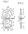
- the electrode rollers 1 are not in direct contact with the metal sheets 2, but rather serve to press a ring 3 made of tungsten, molybdenum or a similar alloy-inert and heat-resistant material which is passed between the electrode roller 1 and the weld metal 2 against the weld metal.
- the ring 3 made of tungsten, molybdenum or the like can be made in any way, for. B. by sintering, forging, casting, cutting, turning or the like.
- the electrode roller 1 is thus to be regarded as the pressing part and also the power supply part and the ring 3 adjacent to the weld metal 2 as the contact part of the device.
- the ring 3 has a larger diameter than the electrode roller 1 and therefore only touches it in the area of the welding point where the current is transferred from the electrode roller 1 via the contact part 3 to the weld metal 2, so that the weld seam 4 is formed.
- the annular contact part 3 runs at a distance from the pressing part 1. It can be supported and guided there by additional support and guide rollers 5, which, like the electrode roller 1 serving as a pressing part, have grooves on its circumference for guiding the annular contact part 3 has.
- One or more of the support and guide rollers can also be designed as drive rollers and driven synchronously with the drive of the pressing part 1 and with the feed of the weld metal 2.
- a cleaning station consisting of a heating element 6, a wire brush 7 and a collector 8 and a cooling station with a fan 9.
- Corresponding devices can of course also be provided for the upper contact part 3.
- the contact part 3 can have different cross-sectional shapes, e.g. B. round, square, wedge-shaped, as they are useful for achieving an optimal weld, the highest possible contact pressure and / or the best possible guidance on the contact part 1 or the guide rollers 5.
- each electrode consists of a roller-shaped pressing part 1, which, in contrast to the previous embodiments, does not have to be rotatably mounted.
- a ring 3 made of tungsten, molybdenum or the like can be rotated by means of a ring of rollers 10 in the manner of a Roller bearing mounted so that it can perform a circular movement around the pressing part 3.
- Welding pressure and welding current are transmitted from the pressing part 1 via the rollers 10 to the ring 3 serving as the contact part and from there onto the weld metal 2.
- the lower electrode in FIG. 3 has the same structure as the upper electrode, which is therefore not shown in detail.
- an external drive roller 5 can serve.
- FIGS. 5 and 6 differs from that according to FIGS. 3 and 4 in that the annular contact part 3 is mounted in a groove of the pressing part 1 by means of balls 10 '. Furthermore, a separate drive roller for the contact part 3 is omitted, so that it is driven by entrainment through the weld metal 2. Otherwise, the structure and mode of operation are the same as in the previous embodiment.
- the roller electrode shown in FIG. 7 has a pressing part 1 designed as a copper roller, which is divided into two halves 1 a and 1 b, which can be clamped against one another by screws 15.
- the two parts la and lb form a groove on the circumference into which an annular contact part 3 made of a heat-resistant and alloy-inert material, for. B.
- the screws 15 are preferably designed as expansion screws so that they generate a clamping force that is largely independent of the heating of the pressing part 1.
- the space between the two halves la and lb of the pressing part 1 can be designed as a cavity 17 for the circulation of a coolant. Overlap by means the ring flanges 18, 19 of the two halves la and lb can provide an additional seal against radial leakage of the coolant.
- the devices for supplying the coolant are not shown, nor is the connection of the pressing part 1 z. B. with a drive shaft that allows the application of a feed force on the roller electrode on the weld metal.
- the roller electrode shown in FIG. 8 differs from that according to FIG. 7 mainly in that the clamping surfaces 13, 14 with which the electrode halves la, lb are clamped against the contact part 3 have an inclined course with respect to the electrode axis, that is to say conical surfaces are. Accordingly, the associated contact surfaces of the contact part 3 are inclined conically. On the outside, as in the embodiment according to FIG. 7, the contact part 3 has a cutting-like course corresponding to the desired width of the weld seam to be produced.
- the two electrode halves la and lb are braced against one another by means of screws 15 with the interposition of disc springs 16.
- These disc springs can do both axial thermal expansion and the axial distance changes between the two parts that occur in the case of radial thermal expansion due to the oblique clamping surfaces 13, 14 Take up la and lb of the pressing part and maintain a substantially constant clamping force.
- the clamping surfaces 11, 12, 13, 14 and / or the contact surfaces of the contact part 3 lying against you can with a suitable coating, e.g. B. Silver plating to be provided in order to favor the transfer of electricity and heat and / or to reduce the friction during temperature-related relative movements.
- a suitable coating e.g. B. Silver plating to be provided in order to favor the transfer of electricity and heat and / or to reduce the friction during temperature-related relative movements.
- the exemplary embodiments according to FIGS. 7 and 8 can also be modified so that the contact part is not arranged concentrically to the pressing part, but eccentrically similar to the embodiment according to FIG. 1 and can then also perform a kind of wobbling movement relative to the pressing part.
- other clamping means known to the person skilled in the art can also be used instead of screws and springs.
- band-shaped or elliptical cross sections can also be used.
- the various drive options are also conceivable. You can drive the contact part, which transmits its movement to the contact part. Conversely, one can drive the contact part, which in turn takes the pressing part with it. Finally, it is possible to have a feed drive acting only on the weld metal, so that the movement of the contact part and pressing part takes place exclusively by frictional entrainment. Particularly good welding results should be achievable if both the weld metal and the electrode system are driven synchronously.
- a device according to the invention makes it possible to work with significantly higher contact pressures compared to copper wire electrodes, thereby achieving good pinch seam formation and thickening of the material Avoid seam area and to achieve an electrode penetration depth required for the desired current concentration. Due to the good heat resistance of tungsten or comparable materials, there is practically no change in cross-section and / or elongation of the contact part. Also finds no or only insignificant removal of coating metal such as z. B. tin instead of the weld, so that a weakening of the corrosion protection in the seam area is avoided.
Landscapes
- Engineering & Computer Science (AREA)
- Mechanical Engineering (AREA)
- Electrical Discharge Machining, Electrochemical Machining, And Combined Machining (AREA)
- Resistance Welding (AREA)
Applications Claiming Priority (4)
| Application Number | Priority Date | Filing Date | Title |
|---|---|---|---|
| DE2919365 | 1979-05-14 | ||
| DE19792919365 DE2919365C2 (de) | 1979-05-14 | 1979-05-14 | Vorrichtung zum Widerstands-RoUennahtschweißen |
| DE3001832 | 1980-01-18 | ||
| DE19803001832 DE3001832A1 (de) | 1980-01-18 | 1980-01-18 | Vorrichtung zum widerstands-rollennahtschweissen |
Publications (2)
| Publication Number | Publication Date |
|---|---|
| EP0019196A1 true EP0019196A1 (fr) | 1980-11-26 |
| EP0019196B1 EP0019196B1 (fr) | 1983-09-28 |
Family
ID=25779102
Family Applications (1)
| Application Number | Title | Priority Date | Filing Date |
|---|---|---|---|
| EP80102477A Expired EP0019196B1 (fr) | 1979-05-14 | 1980-05-07 | Dispositif de soudage par résistance d'un joint à molettes |
Country Status (7)
| Country | Link |
|---|---|
| US (1) | US4368372A (fr) |
| EP (1) | EP0019196B1 (fr) |
| AR (1) | AR225309A1 (fr) |
| AU (1) | AU5826580A (fr) |
| BR (1) | BR8002965A (fr) |
| CA (1) | CA1134456A (fr) |
| ES (1) | ES8101963A1 (fr) |
Cited By (2)
| Publication number | Priority date | Publication date | Assignee | Title |
|---|---|---|---|---|
| RU2147269C1 (ru) * | 1999-07-06 | 2000-04-10 | Закрытое акционерное общество "Интеллект" | Дисковый электрод |
| WO2017041786A1 (fr) * | 2015-09-07 | 2017-03-16 | Brandenburgische Technische Universität Cottbus-Senftenberg | Électrode de soudage à la molette |
Families Citing this family (6)
| Publication number | Priority date | Publication date | Assignee | Title |
|---|---|---|---|---|
| US5089682A (en) * | 1988-03-28 | 1992-02-18 | Davies Joseph R | Roller electrodes for electric-resistance welding machine |
| WO2000066313A1 (fr) * | 1999-04-30 | 2000-11-09 | Kilian, Hanspeter | Tete de soudage roulante |
| US20130319649A1 (en) * | 2011-09-16 | 2013-12-05 | Ksm Co., Ltd. | Cooling ring for welding bellows generating less metal powder |
| DE102015104635B3 (de) * | 2015-03-26 | 2016-03-03 | Thyssenkrupp Ag | Verfahren und Vorrichtung zum Widerstandsschweißen von Sandwichblechen |
| JP6767523B2 (ja) * | 2019-01-09 | 2020-10-14 | 本田技研工業株式会社 | 電極姿勢確認装置及び電極姿勢確認方法 |
| WO2024051944A1 (fr) * | 2022-09-08 | 2024-03-14 | Soudronic Ag | Procede et dispositif de nettoyage de la surface d'un fil metallique ou d'une bande metallique |
Citations (7)
| Publication number | Priority date | Publication date | Assignee | Title |
|---|---|---|---|---|
| GB191508543A (en) * | 1915-06-09 | 1916-03-23 | Britsh Thomson Houston Company | Improvements in and relating to Electric Welding and Brazing Apparatus. |
| DE330571C (de) * | 1919-06-24 | 1921-04-22 | Richard Mack | Elektrische Widerstandsschweissmaschine |
| US1943771A (en) * | 1929-08-19 | 1934-01-16 | Budd Edward G Mfg Co | Welding electrode |
| US3015713A (en) * | 1959-03-09 | 1962-01-02 | Raytheon Co | Automatic decontamination of welding electrodes |
| US3596225A (en) * | 1969-07-15 | 1971-07-27 | Continental Can Co | Pigtail rotary joint |
| FR2213833A1 (en) * | 1973-01-15 | 1974-08-09 | Sato Ryoda | Electric seam-welding machine - with rotating electrode and flexible current leads that do not impair electrode movement |
| FR2369901A1 (fr) * | 1976-11-09 | 1978-06-02 | Fael Sa | Machine de soudage lineaire par resistance |
Family Cites Families (11)
| Publication number | Priority date | Publication date | Assignee | Title |
|---|---|---|---|---|
| US1806949A (en) * | 1931-05-26 | Arc welding chill | ||
| US1176614A (en) * | 1915-01-23 | 1916-03-21 | Gen Electric | Welding pressure-contact. |
| US1300603A (en) * | 1918-09-07 | 1919-04-15 | Thomson Electric Welding Co | Electric welding apparatus. |
| US1822371A (en) * | 1929-06-20 | 1931-09-08 | Ford Motor Co | Welding machine |
| US2918564A (en) * | 1958-03-13 | 1959-12-22 | John D Russell | Pressure-controllable rotary welding electrodes |
| CH370175A (de) | 1959-06-10 | 1963-06-30 | Soudronic Ag | Widerstands-Schweissmaschine zum kontinuierlichen elektrischen Schweissen von sich überlappenden Blechen |
| LU55729A1 (fr) * | 1968-03-21 | 1969-10-02 | ||
| US3596043A (en) * | 1969-04-11 | 1971-07-27 | Southern Can Co | Method of seam welding overlapping workpieces |
| US3989923A (en) * | 1972-10-11 | 1976-11-02 | International Standard Electric Corporation | Wire heat treating apparatus |
| US4100391A (en) * | 1976-09-13 | 1978-07-11 | Progressive Machinery Corporation | Portable seam welder |
| US4188523A (en) * | 1977-06-15 | 1980-02-12 | Nippon Electric Co., Ltd. | Roll electrode for use in a seam welding machine |
-
1980
- 1980-05-07 EP EP80102477A patent/EP0019196B1/fr not_active Expired
- 1980-05-09 AU AU58265/80A patent/AU5826580A/en not_active Abandoned
- 1980-05-13 ES ES491417A patent/ES8101963A1/es not_active Expired
- 1980-05-13 BR BR8002965A patent/BR8002965A/pt unknown
- 1980-05-13 US US06/149,538 patent/US4368372A/en not_active Expired - Lifetime
- 1980-05-13 AR AR281005A patent/AR225309A1/es active
- 1980-05-14 CA CA000351969A patent/CA1134456A/fr not_active Expired
Patent Citations (7)
| Publication number | Priority date | Publication date | Assignee | Title |
|---|---|---|---|---|
| GB191508543A (en) * | 1915-06-09 | 1916-03-23 | Britsh Thomson Houston Company | Improvements in and relating to Electric Welding and Brazing Apparatus. |
| DE330571C (de) * | 1919-06-24 | 1921-04-22 | Richard Mack | Elektrische Widerstandsschweissmaschine |
| US1943771A (en) * | 1929-08-19 | 1934-01-16 | Budd Edward G Mfg Co | Welding electrode |
| US3015713A (en) * | 1959-03-09 | 1962-01-02 | Raytheon Co | Automatic decontamination of welding electrodes |
| US3596225A (en) * | 1969-07-15 | 1971-07-27 | Continental Can Co | Pigtail rotary joint |
| FR2213833A1 (en) * | 1973-01-15 | 1974-08-09 | Sato Ryoda | Electric seam-welding machine - with rotating electrode and flexible current leads that do not impair electrode movement |
| FR2369901A1 (fr) * | 1976-11-09 | 1978-06-02 | Fael Sa | Machine de soudage lineaire par resistance |
Cited By (2)
| Publication number | Priority date | Publication date | Assignee | Title |
|---|---|---|---|---|
| RU2147269C1 (ru) * | 1999-07-06 | 2000-04-10 | Закрытое акционерное общество "Интеллект" | Дисковый электрод |
| WO2017041786A1 (fr) * | 2015-09-07 | 2017-03-16 | Brandenburgische Technische Universität Cottbus-Senftenberg | Électrode de soudage à la molette |
Also Published As
| Publication number | Publication date |
|---|---|
| AU5826580A (en) | 1980-11-20 |
| CA1134456A (fr) | 1982-10-26 |
| EP0019196B1 (fr) | 1983-09-28 |
| ES491417A0 (es) | 1980-12-16 |
| US4368372A (en) | 1983-01-11 |
| ES8101963A1 (es) | 1980-12-16 |
| BR8002965A (pt) | 1980-12-23 |
| AR225309A1 (es) | 1982-03-15 |
Similar Documents
| Publication | Publication Date | Title |
|---|---|---|
| EP0278098B1 (fr) | Machine soudeuse de joints continus par résistance | |
| EP0019196B1 (fr) | Dispositif de soudage par résistance d'un joint à molettes | |
| DE2752025A1 (de) | Elektrischer kondensator | |
| EP3511103A1 (fr) | Dispositif pour former un fil et chalumeau de soudage doté du dispositif pour former un fil | |
| EP0692334B1 (fr) | Méthode, appareil pour le soudage par rouleaux de réservoirs | |
| DE2730884A1 (de) | Fluessigkeitsgekuehlte elektrode fuer lichtbogenoefen | |
| DE3515833A1 (de) | Vorrichtung zum punktschweissen beschichteter blechteile | |
| DE2919365C2 (de) | Vorrichtung zum Widerstands-RoUennahtschweißen | |
| EP0182328B1 (fr) | Dispositif de soudage électrique par résistance d'un joint à molettes | |
| DE2449225C3 (de) | Verdampfungstiegel für Vakuumbedampfungs anlagen | |
| EP0022123B1 (fr) | Disposition d'électrodes à une machine de soudage de treillis | |
| CH370175A (de) | Widerstands-Schweissmaschine zum kontinuierlichen elektrischen Schweissen von sich überlappenden Blechen | |
| DE2724206C3 (de) | Verfahren und Vorrichtung zum Stumpfschweißen von Stäben aus Metall | |
| DE19703044C2 (de) | Verfahren zur Reinigung von bandförmigem Kupferdraht sowie eine Vorrichtung zur Reinigung von bandförmigem Kupferdraht | |
| EP0159693A2 (fr) | Procédé d'utilisation multiple d'un fil en cuivre comme fil électrode dans le soudage à résistance de cordons longitudinaux | |
| DE3407485A1 (de) | Walzvorrichtung | |
| DE2747221C2 (de) | Elektrische Widerstandsnahtschweißmaschine | |
| EP0166149A1 (fr) | Molette électrode pour le soudage en ligne par résistance électrique | |
| AT511214B1 (de) | Verfahren und vorrichtung zur durchführung einer punktschweissung und elektrodenschutzband | |
| DE4301742A1 (de) | Vorrichtung zum Galvanisieren plattenförmiger Gegenstände, insbesondere von elektronischen Leiterplatten | |
| DE3106894A1 (de) | Einrichtung zum lichtbogenbearbeiten langer werkstuecke | |
| DE2645091C3 (de) | Vorrichtung zum Widerstandsschweißen von Blechteilen zu Eckverbindungen | |
| AT379099B (de) | Verfahren zum auftragsschweissen von blechen | |
| DD253391A1 (de) | Verfahren und einrichtung zur widerstandsrollennahtauftragsschweissung von rotationssymmetrischen teilen | |
| DE3108479A1 (de) | "vorrichtung zum verschweissen der enden von stahlbaendern od.dgl." |
Legal Events
| Date | Code | Title | Description |
|---|---|---|---|
| PUAI | Public reference made under article 153(3) epc to a published international application that has entered the european phase |
Free format text: ORIGINAL CODE: 0009012 |
|
| AK | Designated contracting states |
Designated state(s): BE CH FR GB IT LI NL |
|
| 17P | Request for examination filed |
Effective date: 19810508 |
|
| RAP1 | Party data changed (applicant data changed or rights of an application transferred) |
Owner name: FISCHER, FRITZ, PROF. DR.-ING. Owner name: HABENICHT, GERD, PROF. DR.-ING. |
|
| ITF | It: translation for a ep patent filed | ||
| GRAA | (expected) grant |
Free format text: ORIGINAL CODE: 0009210 |
|
| AK | Designated contracting states |
Designated state(s): BE CH FR GB IT LI NL |
|
| ET | Fr: translation filed | ||
| PLBI | Opposition filed |
Free format text: ORIGINAL CODE: 0009260 |
|
| 26 | Opposition filed |
Opponent name: FAEL S.A. Effective date: 19840627 |
|
| RAP2 | Party data changed (patent owner data changed or rights of a patent transferred) |
Owner name: L. SCHULER GMBH |
|
| RIN2 | Information on inventor provided after grant (corrected) |
Free format text: HABENICHT, GERD, PROF. DR.-ING. * FISCHER, FRITZ, PROF. DR.-ING. |
|
| NLT2 | Nl: modifications (of names), taken from the european patent patent bulletin |
Owner name: L. SCHULER GMBH. TE GOEPPINGEN, BONDSREPUBLIEK DUI |
|
| PLBN | Opposition rejected |
Free format text: ORIGINAL CODE: 0009273 |
|
| STAA | Information on the status of an ep patent application or granted ep patent |
Free format text: STATUS: OPPOSITION REJECTED |
|
| 27O | Opposition rejected |
Effective date: 19860801 |
|
| NLR2 | Nl: decision of opposition | ||
| REG | Reference to a national code |
Ref country code: FR Ref legal event code: TP |
|
| REG | Reference to a national code |
Ref country code: GB Ref legal event code: 732 |
|
| REG | Reference to a national code |
Ref country code: CH Ref legal event code: PUE Owner name: ELPATRONIC AG |
|
| NLS | Nl: assignments of ep-patents |
Owner name: ELPATRONIC AG TE ZUG, ZWITSERLAND. |
|
| ITPR | It: changes in ownership of a european patent |
Owner name: CESSIONE;ELPATRONIC AG |
|
| ITTA | It: last paid annual fee | ||
| PGFP | Annual fee paid to national office [announced via postgrant information from national office to epo] |
Ref country code: NL Payment date: 19940531 Year of fee payment: 15 |
|
| PG25 | Lapsed in a contracting state [announced via postgrant information from national office to epo] |
Ref country code: NL Effective date: 19951201 |
|
| NLV4 | Nl: lapsed or anulled due to non-payment of the annual fee |
Effective date: 19951201 |
|
| PGFP | Annual fee paid to national office [announced via postgrant information from national office to epo] |
Ref country code: FR Payment date: 19990416 Year of fee payment: 20 |
|
| PGFP | Annual fee paid to national office [announced via postgrant information from national office to epo] |
Ref country code: CH Payment date: 19990507 Year of fee payment: 20 |
|
| PGFP | Annual fee paid to national office [announced via postgrant information from national office to epo] |
Ref country code: GB Payment date: 19990528 Year of fee payment: 20 |
|
| REG | Reference to a national code |
Ref country code: CH Ref legal event code: PFA Free format text: ELPATRONIC AG,HERTIZENTRUM 6,6303 ZUG (CH) TRANSFER- ELPATRONIC AG,INDUSTRIESTRASSE 35,8962 BERGDIETIKON (CH) |
|
| PGFP | Annual fee paid to national office [announced via postgrant information from national office to epo] |
Ref country code: BE Payment date: 19991122 Year of fee payment: 20 |
|
| BE20 | Be: patent expired |
Free format text: 20000507 *ELPATRONIC A.G. |
|
| PG25 | Lapsed in a contracting state [announced via postgrant information from national office to epo] |
Ref country code: CH Free format text: LAPSE BECAUSE OF EXPIRATION OF PROTECTION Effective date: 20000506 Ref country code: GB Free format text: LAPSE BECAUSE OF EXPIRATION OF PROTECTION Effective date: 20000506 Ref country code: LI Free format text: LAPSE BECAUSE OF EXPIRATION OF PROTECTION Effective date: 20000506 |
|
| REG | Reference to a national code |
Ref country code: GB Ref legal event code: PE20 Effective date: 20000506 Ref country code: CH Ref legal event code: PL |