EP0019210B1 - Akustische sphärische Linse und Verfahren zu deren Herstellung - Google Patents
Akustische sphärische Linse und Verfahren zu deren Herstellung Download PDFInfo
- Publication number
- EP0019210B1 EP0019210B1 EP80102502A EP80102502A EP0019210B1 EP 0019210 B1 EP0019210 B1 EP 0019210B1 EP 80102502 A EP80102502 A EP 80102502A EP 80102502 A EP80102502 A EP 80102502A EP 0019210 B1 EP0019210 B1 EP 0019210B1
- Authority
- EP
- European Patent Office
- Prior art keywords
- lens
- bubble
- glassy carbon
- substance
- mold
- Prior art date
- Legal status (The legal status is an assumption and is not a legal conclusion. Google has not performed a legal analysis and makes no representation as to the accuracy of the status listed.)
- Expired
Links
- 238000004519 manufacturing process Methods 0.000 title claims description 11
- VYPSYNLAJGMNEJ-UHFFFAOYSA-N Silicium dioxide Chemical compound O=[Si]=O VYPSYNLAJGMNEJ-UHFFFAOYSA-N 0.000 claims description 55
- 239000011521 glass Substances 0.000 claims description 25
- 239000000126 substance Substances 0.000 claims description 22
- 238000000034 method Methods 0.000 claims description 21
- 229910021397 glassy carbon Inorganic materials 0.000 claims description 20
- 239000000463 material Substances 0.000 claims description 11
- 238000010438 heat treatment Methods 0.000 claims description 9
- 230000008018 melting Effects 0.000 claims description 6
- 238000002844 melting Methods 0.000 claims description 6
- 238000005498 polishing Methods 0.000 claims description 6
- 239000002184 metal Substances 0.000 claims description 5
- 229910052751 metal Inorganic materials 0.000 claims description 5
- 239000005350 fused silica glass Substances 0.000 claims description 3
- 238000003754 machining Methods 0.000 claims description 3
- 239000005331 crown glasses (windows) Substances 0.000 claims description 2
- 239000005308 flint glass Substances 0.000 claims description 2
- 239000010453 quartz Substances 0.000 claims description 2
- 239000011248 coating agent Substances 0.000 claims 1
- 238000000576 coating method Methods 0.000 claims 1
- 239000000377 silicon dioxide Substances 0.000 description 23
- 239000007789 gas Substances 0.000 description 13
- KAESVJOAVNADME-UHFFFAOYSA-N Pyrrole Chemical compound C=1C=CNC=1 KAESVJOAVNADME-UHFFFAOYSA-N 0.000 description 10
- HYBBIBNJHNGZAN-UHFFFAOYSA-N furfural Chemical compound O=CC1=CC=CO1 HYBBIBNJHNGZAN-UHFFFAOYSA-N 0.000 description 10
- 239000013078 crystal Substances 0.000 description 8
- 239000000203 mixture Substances 0.000 description 6
- VEXZGXHMUGYJMC-UHFFFAOYSA-N Hydrochloric acid Chemical compound Cl VEXZGXHMUGYJMC-UHFFFAOYSA-N 0.000 description 4
- 238000003763 carbonization Methods 0.000 description 4
- 239000011368 organic material Substances 0.000 description 4
- 230000000694 effects Effects 0.000 description 3
- 239000007788 liquid Substances 0.000 description 3
- 238000006116 polymerization reaction Methods 0.000 description 3
- XLYOFNOQVPJJNP-UHFFFAOYSA-N water Substances O XLYOFNOQVPJJNP-UHFFFAOYSA-N 0.000 description 3
- XLOMVQKBTHCTTD-UHFFFAOYSA-N Zinc monoxide Chemical compound [Zn]=O XLOMVQKBTHCTTD-UHFFFAOYSA-N 0.000 description 2
- 239000003463 adsorbent Substances 0.000 description 2
- 239000003054 catalyst Substances 0.000 description 2
- 239000012141 concentrate Substances 0.000 description 2
- 238000010276 construction Methods 0.000 description 2
- 238000001816 cooling Methods 0.000 description 2
- 238000001514 detection method Methods 0.000 description 2
- 238000005530 etching Methods 0.000 description 2
- 238000009776 industrial production Methods 0.000 description 2
- 239000000843 powder Substances 0.000 description 2
- 239000011369 resultant mixture Substances 0.000 description 2
- 238000007711 solidification Methods 0.000 description 2
- 230000008023 solidification Effects 0.000 description 2
- WURBVZBTWMNKQT-UHFFFAOYSA-N 1-(4-chlorophenoxy)-3,3-dimethyl-1-(1,2,4-triazol-1-yl)butan-2-one Chemical compound C1=NC=NN1C(C(=O)C(C)(C)C)OC1=CC=C(Cl)C=C1 WURBVZBTWMNKQT-UHFFFAOYSA-N 0.000 description 1
- RZVAJINKPMORJF-UHFFFAOYSA-N Acetaminophen Chemical compound CC(=O)NC1=CC=C(O)C=C1 RZVAJINKPMORJF-UHFFFAOYSA-N 0.000 description 1
- OKTJSMMVPCPJKN-UHFFFAOYSA-N Carbon Chemical compound [C] OKTJSMMVPCPJKN-UHFFFAOYSA-N 0.000 description 1
- 230000005540 biological transmission Effects 0.000 description 1
- 229910052799 carbon Inorganic materials 0.000 description 1
- 239000003575 carbonaceous material Substances 0.000 description 1
- 239000005539 carbonized material Substances 0.000 description 1
- 238000010586 diagram Methods 0.000 description 1
- 239000012153 distilled water Substances 0.000 description 1
- 238000001035 drying Methods 0.000 description 1
- 230000008020 evaporation Effects 0.000 description 1
- 238000001704 evaporation Methods 0.000 description 1
- 230000001747 exhibiting effect Effects 0.000 description 1
- 238000002474 experimental method Methods 0.000 description 1
- -1 for example Substances 0.000 description 1
- 229910002804 graphite Inorganic materials 0.000 description 1
- 239000010439 graphite Substances 0.000 description 1
- 238000009659 non-destructive testing Methods 0.000 description 1
- 239000005416 organic matter Substances 0.000 description 1
- 239000011505 plaster Substances 0.000 description 1
- 229920003023 plastic Polymers 0.000 description 1
- 239000004033 plastic Substances 0.000 description 1
- 239000005297 pyrex Substances 0.000 description 1
- 229910052594 sapphire Inorganic materials 0.000 description 1
- 239000010980 sapphire Substances 0.000 description 1
- 238000005245 sintering Methods 0.000 description 1
- 238000004611 spectroscopical analysis Methods 0.000 description 1
- 238000004544 sputter deposition Methods 0.000 description 1
- 239000010409 thin film Substances 0.000 description 1
- 239000011787 zinc oxide Substances 0.000 description 1
Images


Classifications
-
- G—PHYSICS
- G10—MUSICAL INSTRUMENTS; ACOUSTICS
- G10K—SOUND-PRODUCING DEVICES; METHODS OR DEVICES FOR PROTECTING AGAINST, OR FOR DAMPING, NOISE OR OTHER ACOUSTIC WAVES IN GENERAL; ACOUSTICS NOT OTHERWISE PROVIDED FOR
- G10K11/00—Methods or devices for transmitting, conducting or directing sound in general; Methods or devices for protecting against, or for damping, noise or other acoustic waves in general
- G10K11/18—Methods or devices for transmitting, conducting or directing sound
- G10K11/26—Sound-focusing or directing, e.g. scanning
- G10K11/30—Sound-focusing or directing, e.g. scanning using refraction, e.g. acoustic lenses
-
- Y—GENERAL TAGGING OF NEW TECHNOLOGICAL DEVELOPMENTS; GENERAL TAGGING OF CROSS-SECTIONAL TECHNOLOGIES SPANNING OVER SEVERAL SECTIONS OF THE IPC; TECHNICAL SUBJECTS COVERED BY FORMER USPC CROSS-REFERENCE ART COLLECTIONS [XRACs] AND DIGESTS
- Y10—TECHNICAL SUBJECTS COVERED BY FORMER USPC
- Y10T—TECHNICAL SUBJECTS COVERED BY FORMER US CLASSIFICATION
- Y10T29/00—Metal working
- Y10T29/42—Piezoelectric device making
-
- Y—GENERAL TAGGING OF NEW TECHNOLOGICAL DEVELOPMENTS; GENERAL TAGGING OF CROSS-SECTIONAL TECHNOLOGIES SPANNING OVER SEVERAL SECTIONS OF THE IPC; TECHNICAL SUBJECTS COVERED BY FORMER USPC CROSS-REFERENCE ART COLLECTIONS [XRACs] AND DIGESTS
- Y10—TECHNICAL SUBJECTS COVERED BY FORMER USPC
- Y10T—TECHNICAL SUBJECTS COVERED BY FORMER US CLASSIFICATION
- Y10T29/00—Metal working
- Y10T29/49—Method of mechanical manufacture
- Y10T29/49805—Shaping by direct application of fluent pressure
-
- Y—GENERAL TAGGING OF NEW TECHNOLOGICAL DEVELOPMENTS; GENERAL TAGGING OF CROSS-SECTIONAL TECHNOLOGIES SPANNING OVER SEVERAL SECTIONS OF THE IPC; TECHNICAL SUBJECTS COVERED BY FORMER USPC CROSS-REFERENCE ART COLLECTIONS [XRACs] AND DIGESTS
- Y10—TECHNICAL SUBJECTS COVERED BY FORMER USPC
- Y10T—TECHNICAL SUBJECTS COVERED BY FORMER US CLASSIFICATION
- Y10T29/00—Metal working
- Y10T29/49—Method of mechanical manufacture
- Y10T29/4981—Utilizing transitory attached element or associated separate material
Definitions
- This invention relates to an acoustic spherical lens and a method of manufacturing the same. More particularly, it relates to an acoustic spherical lens suitable for use as acoustic wave focusing means in microscopes, especially ones utilizing high frequency acoustic energy, and to a method of manufacturing the same.
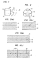
- a circular cylindrical crystal 20 of sapphire or the like has one end face which is a flat surface 21 optically polished, and the other end face which is provided with a hemispherical hole 30.
- a piezoelectric transducer 10 is disposed on the flat surface 21 of the crystal 20.
- a radio frequency signal is applied to the piezoelectric transducer 10 so as to radiate RF acoustic plane waves into the crystal 20.
- the plane acoustic waves are focused on a predetermined focal point S by a concave lens formed by the boundary between the crystal 20 and a medium 40 as defined on the hemispherical hole 30.
- a concave lens formed by the boundary between the crystal 20 and a medium 40 as defined on the hemispherical hole 30.
- the focused acoustic beam is subjected to disturbances such as reflection, scattering, transmission and attenuation by a specimen (not shown) located in the vicinity of the focal point.
- a specimen not shown
- an electric signal reflective of the elastic property of the specimen can be obtained.
- the foregoing crystal system may be utilized again.
- a similar crystal system may be con- focally opposed and used.
- the prior art has its focusing based on the concave lens which exploits the difference of acoustic velocities in the crystal and the medium. Accordingly, in order to obtain a spherical lens having an excellent focusing property, it is essential to endow a crystal with an excellent flatness and to form a hemispherical hole of excellent sphericalness. More specifically, a spherical surface must not have an unevenness exceeding a maximum of 1/10 of the acoustic wavelength in order to operate as the lens. This corresponds to the order of 0.1 11m in case of acoustic waves at 1 GHz.
- such lens is machined by a polishing method.
- the machining based on the polishing method is an extraordinarily difficult job, and a lens with an aperture of 0.5 mm is laboriously fabricated.
- This invention has been made in view of the above drawbacks, and has for its object to provide an acoustic spherical lens which has a minute numerical aperture and whose surface is a mirror surface, as well as a method of manufacturing the same.
- Bubbles which are sporadical in a silica plate exist as spheres in various sizes ranging from larger ones of 0.5 mm to smaller ones of 10 ⁇ m. It is therefore possible to fabricate spherical lenses which have minute numerical apertures unfeasible with the polishing method as well as excellent flatnesses and spheri- calnesses. Emphasis is to be placed on the fact that, although the existence of the bubbles themselves has heretofore been known, it is the substance of this invention that the bubbles existent in the vitreous materials have been found to be very useful for the acoustic spherical lenses.
- This invention shall include also a method for forming and utilizing such bubbles in a process which can be put into industrial production.
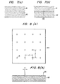
- the upper surface of the silica plate 62 is covered with a mask 63 in which circles R having appropriate diameters d (0.1 mmo-0.05 mmo) are regularly arranged at spacings I.
- a mask 63 in which circles R having appropriate diameters d (0.1 mmo-0.05 mmo) are regularly arranged at spacings I.
- the plate structure having the perfect spherical holes 64 is polished from the side of the silica plate 62 until the polished surface reaches the equatorial plane of the spheres 64.
- hemispherical holes can be formed on the surface of the silica plate 61 in large numbers.
- the shapes of the holes are precisely measured, only hemispheres in a required shape are selected, and the silica plate 61 is cut out into the shape of a circular cylinder with a diameter D as shown in Figure 6(a).
- the circular cylinder is worked into a predetermined lens form, and a piezoelectric transducer 10 is stuck on an end face 66 opposite to the hemispherical hole 64. Then, a spherical lens is obtained.
- silica plates have been employed, it is to be understood that similar effects are produced even with other glasses including flint glass, crown glass, etc.
- the second embodiment exploits the fact that the same phenomenon as in the first embodiment arises in melted surface between glass and metal.
- a glass plate 81 and a plate 82 both surfaces of which have been polished well are stacked.
- absorbed gases outgassed from both plates and gases intervening between the contact surfaces of both plates concentrate on one point in the shape of a perfect sphere.
- a point sphere 83 remains in the vicinity of the contact interface of both plates as shown in Figure 7(b).
- the upper surface of the plate 82 shown in Figures 8(a), 8(b), is covered with a mask 84 in which circles R having appropriate diameters d (0.1 mmo-0.05 mmo) are regularly arranged at spacings I. Etching is carried out in this state so as to prepare the plate 82 in which a large number of concave parts are regularly arranged.
- the plate 82 thus prepared and the glass plate 81 are stacked as in the first embodiment, and the stacked structure is heated up to a temperature near the melting point of the glass. Then, the gases in a specified volume confined in the concave parts at the contact interface of both plates appear as bubbles of perfect spherical shape. The structure is cooled and solidified in this state.
- the present embodiment utilizes the melted surface between different substances. It is therefore desirable to employ glass and metal which have thermal expansion coefficients close to each other. It is to be understood, however, that the invention is not restricted to the materials in the present embodiment.
- the third embodiment positively exploits a material which produces gases being the sources of bubbles, in the foregoing embodiments.
- an adsorbent material for example, fritted glass powder is put into the concave parts 95. Since the fritted glass is highly adsorbent and contains large quantities of gases adsorbed therein, it produces large quantities of gases when heated and fused, and perfect spheres 93 as shown in Figure 9(b) can be formed in the contact surfaces of the silica plate 92.
- spherical lenses can be readily fabricated by utilizing the bubbles appearing due to the intervention of the fritted glass powder in the concave parts.
- the fourth embodiment causes a bubble to appear by externally introducing a gas between metal and glass which have been polished into mirror surfaces.
- a plate 100 is provided with a small orifice 110 having a diameter of about 0.03 mm.
- a glass plate 101 is stacked on the orificed plate 100 as shown in Figure 10(b), and the stacked structure is heated to a temperature near the melting point of the glass. Under this state, a gas is blown through the orifice 110 towards the glass plate.
- a bubble 102 can be formed along the orifice 110 as shown in Figure 10(c), and moreover, it can be prevented from separating from the orifice.
- the glass plate having a spherical hole can be prepared as in the foregoing embodiments.
- the present embodiment has the first feature that the diameter of the bubble can be kept invariable in the cooling by delicately controlling the gaseous pressure during the cooling, and the second feature that the diameter of the sphere of the bubble can be made to have a desired value by adjusting the gaseous pressure and selecting the orifice diameter.
- All the ensuing embodiments concern a method wherein the same spherical holes are formed in large quantities by a replica method for a single spherical hole once obtained with any of the foregoing embodiments.
- the fifth embodiment starts from a glass plate 120 as shown in Figure 11 which has a spherical hole 121 formed by the previous embodiment.
- the whole surface of the glass plate 120 is coated with an organic substance as shown in Figure 12(a), and after heating and drying the structure, the glass plate 120 and an organic plate 130 are separated.
- a sphere 131 of quite the inverse shape to the shape of the surface of the glass plate 120 as shown in Figure 12(b) can be reproduced onto the organic plate 130.
- hydrochloric acid As a catalyst for polymerization, hydrochloric acid (at a concentration of 36%) is diluted 4-5 times with distilled water and is added 1-3% to the mixture consisting of furfural and pyrrole. When the resultant mixture is heated to 50-80'C and stirred, it begins to polymerize in 2 ⁇ 10 minutes, and it becomes a viscous liquid after completion of the polymerization reaction.
- the organic material 130 on which the shape on the silica plate has been reproduced is first subjected to a preliminary solidification by heating it in the air from room temperature to 80°C at a rate of at most 0.5°C/min. Further, it is heated to 450°C in a vacuum. Thus, a solidification process is completed.
- the organic material 130 is heated to 1,000°C in vacuum at a temperature raising rate of about 10°C/min., and it is finally heated to 1,300°C-2,500°C. Then, the organic material 130 turns into glassy carbon.
- a silica glass plate 140 having a predetermined thickness is stacked on the glassy carbon plate 130 as shown in Figure 13(a), and the stacked structure is heated in a certain specified atmosphere. Then, the silica glass is fused and bonded onto the glassy carbon plate 130 as shown in Figure 13(b).
- the shape on the surface of the glassy carbon plate 130 can be transferred onto the surface of the silica glass 140, and the transferred shape is quite inverse.
- the silica glass 140 thus obtained is worked by steps as shown in Figures 14(a) and 14(b), whereby a spherical lens in the final shape shown in Figure 14(c) can be fabricated.
- the sixth embodiment fabricates spherical lenses through reproduction with a mold by utilizing the spherical lens obtained in the foregoing embodiment.
- the manufacturing method according to the present embodiment starts from a pattern 300 for a lens, as shown in Figure 15 which includes a concave 301 obtained by any of the foregoing embodiments.
- a female mold is prepared.
- the lens pattern 300 is buried in a substance 302 into which the shape of the lens pattern 300 can be precisely transferred (a substance such as, for example, plaster and plastics), whereupon the mold substance 302 is hardened.
- a substance 302 such as, for example, plaster and plastics
- the mold substance 302 is hardened.
- a mold 302 of the shape shown in Figure 1 6(b) can be fabricated.
- the surface of the lens pattern 300 is plated with a metal 303 to a predetermined thickness as shown in Figure 17(a), whereupon both are separated.
- a mold 303 of the shape shown in Figure 17(b) can be fabricated.
- the glassy carbon is a carbonized material obtained by heating and hardening an organic matter. It is a carbon material whose behaviour is different from that of usual graphite and is rather similar to that of glass, and it has the feature of exhibiting quite no anisotropy.
- furfural C 5 H 6 O 2
- pyrrole C4HN
- the liquid is heated in the air from room temperature to 80°C at a rate of at most 0.5°C/minute. Then, the preliminary heating is completed. Since the glassy carbon is separated from the mold under this state, it is taken out. When it is heated in a vacuum up to 1,300°C ⁇ 2,500°C, a spherical lens 304 perfectly turned into glassy carbon as shown in Figure 21 can be fabricated.
- the spherical lens 304 made of glassy carbon as thus fabricated has a conductivity of ⁇ 10 -1 Q.cm and mechanical properties similar to those of glasses, a Young's modulus of ⁇ 3 ⁇ 10 10 N/cm 2 , a density of 1.5x 1 03 kg/m 3 and an acoustic velocity of -4,600 m/s, which are equivalent to the performance of pyrex glass.
- the glassy carbon separates from the mold as described above, it can be used for the subsequent manufacture of lenses, and it becomes possible to manufacture lenses of uniform characteristics.
- glassy carbon has been employed, a similar effect can be achieved even with another glassy carbon, for example, one under the tradename “Glassycarbon” or one under the tradename “Cellulose-carbon”.
- a piezoelectric thin film 305 of zinc oxide or the like is deposited directly on the flat surface by a process such as sputtering and is overlaid with an upper electrode 306 by evaporation.
- a piezoelectric transducer 307 is formed.
- the present embodiment has the advantage that the spherical lens 304 functions as a low electrode and simultaneously holds the ground potential when contacted with a case (not shown), thereby serving for electrostatic shielding.
- acoustic spherical lenses for focusing high frequency acoustic waves can be industrially produced in large quantities without relying on the masterly performance-like polishing.
- the effect of this invention is greatly mighty in various industrial apparatuses employing focused beams of high frequency acoustic waves, for example, an acoustic, microscope, an ultrasonic spectroscopy, and a non-destructive testing instrument for revealing a small area.
Landscapes
- Physics & Mathematics (AREA)
- Engineering & Computer Science (AREA)
- Acoustics & Sound (AREA)
- Multimedia (AREA)
- Surface Treatment Of Glass (AREA)
- Investigating Or Analyzing Materials By The Use Of Ultrasonic Waves (AREA)
Claims (13)
Applications Claiming Priority (4)
| Application Number | Priority Date | Filing Date | Title |
|---|---|---|---|
| JP57096/79 | 1979-05-11 | ||
| JP5709679A JPS55149998A (en) | 1979-05-11 | 1979-05-11 | Sound sperical lense |
| JP79209/79 | 1979-06-25 | ||
| JP7920979A JPS564191A (en) | 1979-06-25 | 1979-06-25 | Producing sounddwave concentrating convexx lens |
Publications (3)
| Publication Number | Publication Date |
|---|---|
| EP0019210A2 EP0019210A2 (de) | 1980-11-26 |
| EP0019210A3 EP0019210A3 (en) | 1981-01-07 |
| EP0019210B1 true EP0019210B1 (de) | 1985-02-06 |
Family
ID=26398117
Family Applications (1)
| Application Number | Title | Priority Date | Filing Date |
|---|---|---|---|
| EP80102502A Expired EP0019210B1 (de) | 1979-05-11 | 1980-05-07 | Akustische sphärische Linse und Verfahren zu deren Herstellung |
Country Status (3)
| Country | Link |
|---|---|
| US (2) | US4384231A (de) |
| EP (1) | EP0019210B1 (de) |
| DE (1) | DE3070095D1 (de) |
Cited By (1)
| Publication number | Priority date | Publication date | Assignee | Title |
|---|---|---|---|---|
| DE3718972A1 (de) * | 1986-06-06 | 1987-12-17 | Olympus Optical Co | Akustische linse fuer schallmikroskope |
Families Citing this family (14)
| Publication number | Priority date | Publication date | Assignee | Title |
|---|---|---|---|---|
| JPS56103327A (en) * | 1980-01-21 | 1981-08-18 | Hitachi Ltd | Ultrasonic image pickup apparatus |
| US4551647A (en) * | 1983-03-08 | 1985-11-05 | General Electric Company | Temperature compensated piezoelectric transducer and lens assembly and method of making the assembly |
| US4692653A (en) * | 1984-03-23 | 1987-09-08 | Hitachi, Ltd. | Acoustic transducers utilizing ZnO thin film |
| US4733380A (en) * | 1984-12-26 | 1988-03-22 | Schlumberger Technology Corporation | Apparatus and method for acoustically investigating a casing set in a borehole |
| US4726829A (en) * | 1986-12-16 | 1988-02-23 | The United States Of America As Represented By The Department Of Energy | Fabrication of precision glass shells by joining glass rods |
| US4751530A (en) * | 1986-12-19 | 1988-06-14 | Xerox Corporation | Acoustic lens arrays for ink printing |
| US4751534A (en) * | 1986-12-19 | 1988-06-14 | Xerox Corporation | Planarized printheads for acoustic printing |
| US4751529A (en) * | 1986-12-19 | 1988-06-14 | Xerox Corporation | Microlenses for acoustic printing |
| DE3724629A1 (de) * | 1987-07-22 | 1989-02-02 | Siemens Ag | Piezoelektrisch anregbares resonanzsystem |
| JP3243047B2 (ja) * | 1993-03-12 | 2002-01-07 | 呉羽化学工業株式会社 | 受波型圧電素子 |
| EP1789137B1 (de) * | 2004-07-23 | 2013-09-04 | Inserm | Ultraschallbehandlungsvorrichtung |
| JP5451014B2 (ja) * | 2008-09-10 | 2014-03-26 | キヤノン株式会社 | 光音響装置 |
| US11400477B2 (en) * | 2018-01-30 | 2022-08-02 | Ford Motor Company | Reversible nozzle in ultrasonic atomizer for clog prevention |
| DE102019102232A1 (de) * | 2018-01-30 | 2019-08-01 | Ford Motor Company | Ultraschallzerstäuber mit akustischer fokussiervorrichtung |
Family Cites Families (9)
| Publication number | Priority date | Publication date | Assignee | Title |
|---|---|---|---|---|
| US2949772A (en) * | 1954-12-10 | 1960-08-23 | Kritz Jack | Flowmeter |
| GB851099A (en) * | 1959-06-24 | 1960-10-12 | Mullard Ltd | Seed-glass tubes and rods |
| US3155748A (en) | 1960-08-03 | 1964-11-03 | American Optical Corp | Method of making optical components |
| US3961927A (en) * | 1973-03-05 | 1976-06-08 | Pilkington Brothers Limited | Apparatus and method for moulding glass objects |
| US3958559A (en) * | 1974-10-16 | 1976-05-25 | New York Institute Of Technology | Ultrasonic transducer |
| JPS5550438B2 (de) * | 1974-11-25 | 1980-12-18 | ||
| US4001766A (en) * | 1975-02-26 | 1977-01-04 | Westinghouse Electric Corporation | Acoustic lens system |
| US4097835A (en) * | 1976-09-20 | 1978-06-27 | Sri International | Dual transducer arrangement for ultrasonic imaging system |
| US4184094A (en) * | 1978-06-01 | 1980-01-15 | Advanced Diagnostic Research Corporation | Coupling for a focused ultrasonic transducer |
-
1980
- 1980-04-30 US US06/145,146 patent/US4384231A/en not_active Expired - Lifetime
- 1980-05-07 DE DE8080102502T patent/DE3070095D1/de not_active Expired
- 1980-05-07 EP EP80102502A patent/EP0019210B1/de not_active Expired
-
1982
- 1982-12-08 US US06/448,035 patent/US4433461A/en not_active Expired - Lifetime
Cited By (1)
| Publication number | Priority date | Publication date | Assignee | Title |
|---|---|---|---|---|
| DE3718972A1 (de) * | 1986-06-06 | 1987-12-17 | Olympus Optical Co | Akustische linse fuer schallmikroskope |
Also Published As
| Publication number | Publication date |
|---|---|
| EP0019210A3 (en) | 1981-01-07 |
| US4384231A (en) | 1983-05-17 |
| US4433461A (en) | 1984-02-28 |
| EP0019210A2 (de) | 1980-11-26 |
| DE3070095D1 (en) | 1985-03-21 |
Similar Documents
| Publication | Publication Date | Title |
|---|---|---|
| EP0019210B1 (de) | Akustische sphärische Linse und Verfahren zu deren Herstellung | |
| US5480764A (en) | Gray scale microfabrication for integrated optical devices | |
| US4381963A (en) | Micro fabrication molding process | |
| EP1371092B1 (de) | Verfahren zur strukturierung eines aus glasartigen material bestehenden flächensubstrats | |
| JPS61151501A (ja) | 精密光学部品に使用するに特に適したミラー用基板とその製法 | |
| JP2000231007A (ja) | 凹型微細形状のアレイ状パターン形成方法及びその形成方法を用いて製作される平板型レンズアレイ及び液晶表示素子及び平板型オイルトラップ | |
| JP2006337985A (ja) | ハイサグレンズの製作方法及びこれを利用し製作されたレンズ | |
| JPS60123807A (ja) | 測地光学素子の製造方法 | |
| TWI299093B (en) | Micro-optical device and method of making same | |
| JP2005527459A (ja) | 構造化された表面を有する製品を作製する方法 | |
| JPS6146408B2 (de) | ||
| US8029887B2 (en) | Optical articles and sol-gel process for their manufacture | |
| JP2003211462A (ja) | 非球面構造体の製造方法およびその方法により製造された非球面レンズアレイ用成形型並びに非球面レンズアレイ | |
| CN116282848A (zh) | 一种光学透镜阵列镜片成形过程的曲率调控方法 | |
| JPS642959B2 (de) | ||
| JP2005062664A (ja) | 2次元フォトニック結晶光デバイスおよびその製造方法 | |
| JP3566331B2 (ja) | 光学デバイス・光学デバイス製造方法 | |
| JPS5993495A (ja) | 音響球面レンズ | |
| JPS6188140A (ja) | 音響球面レンズ | |
| JPH11276480A (ja) | 複合圧電振動子およびその製造方法 | |
| JP2001221903A (ja) | ガラスボールレンズ、光ディスク用浮上型ヘッド及び光磁気ディスク用浮上型ヘッド並びにこれらの製造方法 | |
| US20060078271A1 (en) | Optical element | |
| JPH11142607A (ja) | 微小レンズ及び微小レンズアレイ並びにそれらの製造方法 | |
| JP3006301B2 (ja) | ガラス導波路の製造方法 | |
| JP2004035333A (ja) | ガラス材料の加工方法 |
Legal Events
| Date | Code | Title | Description |
|---|---|---|---|
| PUAI | Public reference made under article 153(3) epc to a published international application that has entered the european phase |
Free format text: ORIGINAL CODE: 0009012 |
|
| PUAL | Search report despatched |
Free format text: ORIGINAL CODE: 0009013 |
|
| AK | Designated contracting states |
Designated state(s): DE FR GB |
|
| AK | Designated contracting states |
Designated state(s): DE FR GB |
|
| 17P | Request for examination filed |
Effective date: 19810604 |
|
| GRAA | (expected) grant |
Free format text: ORIGINAL CODE: 0009210 |
|
| AK | Designated contracting states |
Designated state(s): DE FR GB |
|
| REF | Corresponds to: |
Ref document number: 3070095 Country of ref document: DE Date of ref document: 19850321 |
|
| ET | Fr: translation filed | ||
| PLBE | No opposition filed within time limit |
Free format text: ORIGINAL CODE: 0009261 |
|
| STAA | Information on the status of an ep patent application or granted ep patent |
Free format text: STATUS: NO OPPOSITION FILED WITHIN TIME LIMIT |
|
| 26N | No opposition filed | ||
| PGFP | Annual fee paid to national office [announced via postgrant information from national office to epo] |
Ref country code: GB Payment date: 19950427 Year of fee payment: 16 |
|
| PGFP | Annual fee paid to national office [announced via postgrant information from national office to epo] |
Ref country code: FR Payment date: 19950516 Year of fee payment: 16 |
|
| PGFP | Annual fee paid to national office [announced via postgrant information from national office to epo] |
Ref country code: DE Payment date: 19950724 Year of fee payment: 16 |
|
| PG25 | Lapsed in a contracting state [announced via postgrant information from national office to epo] |
Ref country code: GB Effective date: 19960507 |
|
| GBPC | Gb: european patent ceased through non-payment of renewal fee |
Effective date: 19960507 |
|
| PG25 | Lapsed in a contracting state [announced via postgrant information from national office to epo] |
Ref country code: FR Effective date: 19970131 |
|
| PG25 | Lapsed in a contracting state [announced via postgrant information from national office to epo] |
Ref country code: DE Effective date: 19970201 |
|
| REG | Reference to a national code |
Ref country code: FR Ref legal event code: ST |