EP0019472B1 - Fabrication de coquilles de collecteurs pour machines électriques tournantes - Google Patents
Fabrication de coquilles de collecteurs pour machines électriques tournantes Download PDFInfo
- Publication number
- EP0019472B1 EP0019472B1 EP80301610A EP80301610A EP0019472B1 EP 0019472 B1 EP0019472 B1 EP 0019472B1 EP 80301610 A EP80301610 A EP 80301610A EP 80301610 A EP80301610 A EP 80301610A EP 0019472 B1 EP0019472 B1 EP 0019472B1
- Authority
- EP
- European Patent Office
- Prior art keywords
- strip
- ribs
- commutator
- shells
- cylinders
- Prior art date
- Legal status (The legal status is an assumption and is not a legal conclusion. Google has not performed a legal analysis and makes no representation as to the accuracy of the status listed.)
- Expired
Links
- 238000004519 manufacturing process Methods 0.000 title claims description 11
- 239000002184 metal Substances 0.000 claims abstract description 18
- 229910052751 metal Inorganic materials 0.000 claims abstract description 18
- 238000004513 sizing Methods 0.000 claims abstract description 13
- 238000000034 method Methods 0.000 claims description 13
- 238000005096 rolling process Methods 0.000 claims description 13
- 238000005520 cutting process Methods 0.000 claims description 10
- 238000005452 bending Methods 0.000 claims description 9
- 230000015572 biosynthetic process Effects 0.000 claims description 2
- 238000004804 winding Methods 0.000 description 16
- 239000000463 material Substances 0.000 description 11
- 238000000465 moulding Methods 0.000 description 6
- 238000004080 punching Methods 0.000 description 4
- 238000003754 machining Methods 0.000 description 3
- RYGMFSIKBFXOCR-UHFFFAOYSA-N Copper Chemical compound [Cu] RYGMFSIKBFXOCR-UHFFFAOYSA-N 0.000 description 1
- 229910052802 copper Inorganic materials 0.000 description 1
- 239000010949 copper Substances 0.000 description 1
- 230000000694 effects Effects 0.000 description 1
- 239000012777 electrically insulating material Substances 0.000 description 1
- 238000010348 incorporation Methods 0.000 description 1
- 239000011810 insulating material Substances 0.000 description 1
- 230000002093 peripheral effect Effects 0.000 description 1
- 238000003825 pressing Methods 0.000 description 1
- 230000000717 retained effect Effects 0.000 description 1
- 238000007493 shaping process Methods 0.000 description 1
- 210000002105 tongue Anatomy 0.000 description 1
Images



Classifications
-
- H—ELECTRICITY
- H01—ELECTRIC ELEMENTS
- H01R—ELECTRICALLY-CONDUCTIVE CONNECTIONS; STRUCTURAL ASSOCIATIONS OF A PLURALITY OF MUTUALLY-INSULATED ELECTRICAL CONNECTING ELEMENTS; COUPLING DEVICES; CURRENT COLLECTORS
- H01R43/00—Apparatus or processes specially adapted for manufacturing, assembling, maintaining, or repairing of line connectors or current collectors or for joining electric conductors
- H01R43/06—Manufacture of commutators
Definitions
- the present invention relates to commutators for electric rotating machines and in particular to a method of and an apparatus for making co-called commutator shells for use in the manufacture of commutators.
- a common method of manufacturing relatively low price commutators is to form a cylindrical shell of metal which is then moulded full of an electrically insulating material. The shell is then divided parallel to the axis of the cylinder into a plurality of segments which form the segments of the finished commutator.
- An axial bore is normally provided through the moulding material in the centre of the cylinder for mounting the commutator on the rotor of the machine in which it is to be used.
- the metal cylinder or shell before it is moulded and divided into segments, is shaped so as to provide some hook like extensions on the interior of the shell which serve as anchor members to hold the finished segments of the commutator to the insulating moulding material.
- axial cuts are made into each end of the cylinder to produce fingers which are then bent inwards back on themselves to point inwards and towards one another on the inside of the cylinder. These fingers then serve as anchor members.
- DE-A-1955122 shows a method of marking commutator shells in which a strip of material is rolled to produce on one side only integral ribs extending normal to the length of the strip.
- DE-A-1955122 describes calibrating cylinders formed from strips of material.
- EP-A1-0007186 describes use of a multiple press machine in the forming of commutator shells from strip.
- the present invention provides a method of making commutator shells comprising the steps of forming, from strip stock, metal strip ready for use as commutator shells wherein the formed strip is cut into lengths and the lengths are formed into cylinders, said strip forming step including the steps of rolling the strip along its length between a toothed roller and a pressure member, to produce on one side only of the strip integral ribs extending normal to the length of the strip, the teeth of the roller being pressed into said one side of the strip as the roller rotates to displace metal of the strip to form said ribs, and then skiving under the ribs at both ends of the ribs and lifting said ends away from the rest of the strip to form anchor members for the shells, and the method comprising after said strip forming step the further steps of cutting the formed strip into predetermined lengths, bending said lengths into cylinders with the anchor members inwards and forcing the bent cylinders axially through a tapered sizing to form the cylinders with smooth cylindrical outer surface of
- the ribs produced by the rolling step of the method of the invention extend only part way across the width of the strip, the strip having after the rolling step a longitudinally flat portion along one edge of the strip.
- the strip forming step typically further includes the step of cutting slots through the strip extending into the flat portion from the adjacent edge of the strip so as to leave laterally extending fingers along the length of the strip, with the fingers substantially registering with the ribs produced by the rolling step. These fingers provide the winding hooks for the finished commutator.
- the side of the strip opposite to said one side with the ribs is substantially flat right across its width, and said flat edge portion of the strip has, on said one side, a longitudinal step dividing the edge portion into an outer thinner part adjacent the edge of the strip and an inner thicker part which has a thickness not greater than the thickness of the strip between said ribs. Because the thicker part of the flat edge portion of the strip is no thicker than the thickness of the strip between said ribs, it can be seen that both ends of the ribs are accessible to a skiving tool to skive under the ends and lift them away from the rest of the strip.
- the end parts of the laterally extending fingers of the strip are only as thick as said outer thinner part of the flat edge portion, so that the fingers can be relatively easily bent upwards to form the winding tangs.
- the inner thicker part of the fiat edge portion of the strip provides a more rigid support for when the windings of the electric machine are being secured to the winding hooks, as will be explained later herein.
- the strip stock used in the method of the invention may have on one side a longitudinal step between a thicker portion for formation of said ribs and a thinner portion for said flat edge portion of the strip.
- Multiple stage slide press machines are known and commercially available and are widely used for manufacuturing articles from metal strip. Such a machine can be tooled to perform in sequence a number of forming operations on the strip such as punching and bending and cutting operations.
- the present invention further envisages commutator shells made by the method described above, commutators formed from such shells and electric rotating machines containing such commutators.
- a commutator using a commutator shell formed by the method described above is made by moulding insulating material inside said shell to form a commutator blank, and then dividing the shell with axial cuts between said ribs to form separate commutator segments, each with at least one pair of opposed said anchor members. Further, after said moulding step said laterally extending fingers may be bent outwardly to form winding hooks for the commutator.
- apparatus for making commutator shells comprising a multiple stage slide press machine having a plurality of work stages and being arranged to feed metal strip from stock from one stage to another whereby to perform in automatic sequence a plurality of forming operations on said strip, a first work stage of the machine comprising a toothed roller and a pressure member co-operating therewith, the strip being fed from stock to said roller so that as the roller rotates, the teeth of the roller are pressed into one side of the strip displacing metal to form integral ribs on said one side which extend normal to the length of strip, one or more subsequent work stages being arranged to form the ribbed strip into strip ready for use as commutator shells when the formed strip is only cut into lengths and the lengths are formed into cylinders, the or one of the subsequent work stages comprising skiving means arranged to skive under the ends of the ribs and lift said ends away from the rest of the strip to form anchor members for the shells,
- a multi stage slide press machine is adapted to have in effect five stages at which forming operations are performed on metal strip from stock to produce commutator shells.
- the metal strip normally used for commutators is copper strips.
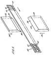
- the strip 10 is fed to stage 1 of the machine from the right hand side in Figures 1 and 2.
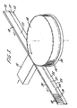
- Stage 1 is illustrated in greater detail in Figure 3 and it can also be seen in Figure 3 that the stock strip 10 has a single step profile with a longitudinal step 11 dividing the stock strip into a thicker portion 12 and a thinner portion 13. A strip of such a stepped profile can readily be made by extruding.
- stage 1 which comprises a toothed roller 14 which cooperates with a pressure pad 15.
- the pressure exerted on the strip 10 by the pressure pad 15 is sufficient to cause the teeth 16 of the roller 14 to penetrate into one side 17 of the strip 10 displacing material of the strip to form alternate. grooves and ribs 18 and 19 respectively.
- the roller-14 is arranged to produce these alternate grooves and ribs 18 and 19 only in the thicker portion 12 of the strip and is arranged also so that the base of the grooves 18 approxi- matel y coincide with the level of the thinner portion 13 of the stock strip, i.e. the thickness of the strip in the grooves 18 is substantially equal to the thickness of the thinner portion 13 of the stock strip.
- a step forming wheel 20 Coaxial with the roller 14 is a step forming wheel 20 which has a diameter slightly greater than the diameter of the circle through the tips of the teeth 16 of the roller 14.
- the wheel 20 is arranged to engage the thinner portion 13 of the stock strip 10 to produce a second longitudinal step 21 in the strip dividing the portion 13 itself into an outer thinner part 22 adjacent the edge 23 of the strip and an inner thicker part 24.
- the strip 25 emerging from stage 1 of the machine has on the side 17 only ribs 19 which are normal to the length of strip.
- the ribs 19 extend only part way across the width of the strip 25 and the portions 22 and 24 of the strip from a longitudinally flat portion of the strip adjacent the edge 23.
- Stage 2 comprises a series of punches 26 which are arranged to punch a corresponding series of slots 27 in the flat portion of the strip 25.
- the punches 26 cooperate with a die block 28 having a series of cavities 29 for receiving the material punched out of the strip 25 by the punches 26.
- The. punches 26 are spaced apart by amounts equal to the spacing of the ribs 18 of the strip 25.
- the machine is arranged so that the punches 26 punch the slots 27 at positions accurately corresponding to the grooves 18 between the ribs 19 so that the punched slots 27 leave behind laterally extending fingers 30 which register with the ribs 19.
- the number of punches 26 depends on the number of segments in the commutator to be made from the shell produced by the machine. Thus, for example, if the shells are to be used in making twenty four segment commutators, then there are twenty five punches 26 arranged to produce twenty four fingers 30 registering with a series of twenty four ribs 19.
- the machine is conveniently arranged to operate stepwise, transferring the strip from stage to stage in the machine in steps and then halting the transfer for the forming operations of the various stages to be made. Thus, between each punching operation in stage 2, the machine transfers the strip 25 by a distance slightly greater than a length of the strip having the desired number of ribs 18, i.e. twenty four for a twenty four segment commutator.
- the slots 27 extend over the full width of the flat portion of the strip, i.e. over both the thinner and thicker parts 22 and 24.
- Stage 3 comprises a pair of opposed skiving knives 32, 33 arranged approximately in the plane of the strip directed at opposite edges thereof.
- the machine is arranged to drive the skiving knives 32 and 33 towards the strip in the direction of arrows 34 and 35 when the strip is halted during the stepwise operation of the machine.
- the skiving knives are positioned so that their cutting edges 36 and 37 engage the ends of the ribs 19 substantially at the level of the grooves 18 between the ribs so as to skive under the ends of the ribs.
- the knives 32 and 33 are provided with bevels 38 and 39 to lift the ends of the ribs 19 away from the rest of the strip as illustrated in Figure 5 at 40.
- the knives 32 and 33 are made just long enough to skive simultaneously under the desired number of ribs for a single commutator shell, i.e. twenty four for a commutator of twenty four segments. Furthermore, the knives are positioned so that the ribs which are skived simultaneously are those which correspond to the set of fingers 30 which was formed by a simultaneous punching operation in stage 2. Although the skiving knives 32 and 33 are shown in Figure 5 with straightline cutting edges and plane bevels, the bevels 38 and 39 may in fact be formed slightly corrugated so that the grooves of the corrugation in the bevels correspond with the ribs 19 during the skiving operation and ensure that the lifted end portions of the ribs 19 are retained correctly positioned and spaced relative to one another.
- the lifted ends 41 of the ribs 19 produced by the skiving knives 32 and 33 will form anchor members in the finished commutator shell.
- stage 4 The strip 42 emerging from stage 3 is fed by the machine to stage 4.
- stage 4 two forming operations are performed on the strip.
- a crop punch 43 co-operating with a die 44 crops from the leading end of the strip 42 a predetermined length 45 of the strip.
- the length 45 is selected to include the desired number of ribs 18 and tongues 30 to produce a commutator shell with the desired number of segments, in the present example 24.
- the machine automatically positions the strip 42 so that the crop punch 43 cuts off the length 45 at the correct position so that the length 45 can form when bent into a cylinder the desired commutator shell.
- a forming punch 46 is moved in the direction of an arrow 47 towards the face of the strip having the anchor members.
- spring loaded bending pad 48 is moved in the direction of an arrow 49 to engage the other plane side of the length 45.
- the form punch 46 and the bending pad 48 are provided with complimentary shapes so as to bend the ends 50 and 51 of the length 45 of the strip between them as illustrated in Figure 6. After bending, the ends 50 and 51 are directed at right angles to the rest of the length 45 and the bent portion of the length 45 is radiused with substantially the radius of the desired cylinder into which the length 45 is to be bent to produce the complete commutator shell.
- stage 4 the machine transfers the bent strip 45 upwards, in Figure 2, transversely of the length of the strip to stage 5 in which again two forming operations take place.
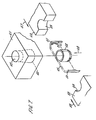
- the bent strip 45 is presented to a pair of forming dies 52 and 53.
- the forming dies 52 and 53 have opposed semicylindrical cut-outs 54 and 55 of substantially the same radius as the cylinder into which the length 45 of strip is to be bent.
- the dies 52 and 53 are brought by the machine together in the directions of the arrows 56 and 57 so that the cut-outs 54 and 55 engage the bent ends 50 and 51 of the length 45 and further bend the length 45 into the complete cylinder shown at 58 in Figure 7.
- stage 4 after the length 45 is bent to the cylinder 58, the cylinder is forced axially in the direction of an arrow 59 into the inwardly tapering entrance 60 of a sizing die 61.
- the upper end 62 of the bore in the sizing die 61 has a minimum diameter equal to the desired outer diameter of the formed commutator shells produced by the machine so that the cylinders 58 pushed through the die 61 in successive stepwise operations of the machine are slightly compressed by the sizing die to have the desired smooth outer diameter.
- the commutator shells produced by the machine are formed with precisely the desired outer diameters so that no further machining is required after the shells are divided to form the segments of the complete commutator.
- the manufacturer of the rotating electric machine it will be understood that it is common practice for the manufacturer of the rotating electric machine to provide a final machining of the commutator after the commutator has been mounted on the rotor axis of the machine to ensure that the segment surfaces are perfectly symmetrical relative to the axis of rotation of the machine's rotor.
- commutators made from commutator shells formed as described above require no further machining before being supplied to the electrical machine manufacturer for incorporation in a machine.
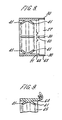
- FIG. 8 A completed commutator shell formed by the machine illustrated in Figures 1 to 7 is illustrated, in schematic form, in Figure 8.
- each finger 30 at the right hand end of the cylinder of the shell registers with a rib 19 the ends of which are lifted from the rest of the shell to form anchor members 41.
- the step 21 formed by stage 1 of the machine is clearly visible and the slots 27 between the fingers 30 extend right across the full width of the flat portion of the strip to the adjacent ends of the ribs 18, so that the fingers 30 include outer thinner parts 63, corresponding to the thinner part 22 of the strip 25 after stage 1, and inner thicker parts 64, corresponding to the thicker part 24 of the strip 25.
- the interior of the shell is filled with an electrically insulating mouldable material so that the anchor members 41 become completely embedded in this material, indicated at 65 in Figure 9.
- a bore may be provided through the centre of the mouldable material 65 for mounting the commutator on a suitable shaft.
- the shell is divided into the various segments of the commutator by axial cuts between adjacent ribs and fingers 30, so that in the twenty four segment example described herein, each segment has a single pair of anchor members 41, formed by a single rib 18, with a single finger 30 extending from one end.
- the fingers 30 of each of the segments can then be bent outwards to the position shown in ghost in Figure 9 to serve as winding hooks or tangs for connecting the rotor windings to the commutator. This is normally done by locating the winding wire behind the bent up hook and then pressing the hook firmly down onto the winding as shown in Figure 9.
- the thicker portions 64 of the fingers 30 provide strengthened regions to withstand the axially inward force when the hooks are pressed down onto the wires of the windings.
- the entire operation of forming the commutator shells, as described in the above example, is performed automatically on the. multi stage slide press machine thereby greatly reducing the cost of producing these shells whilst ensuring that the shells are produced to a relatively tight tolerance and have anchor members enabling the separated segments of the commutator to be firmly anchored to the moulded material of the commutator.
Landscapes
- Engineering & Computer Science (AREA)
- Manufacturing & Machinery (AREA)
- Motor Or Generator Current Collectors (AREA)
- Manufacture Of Motors, Generators (AREA)
- Iron Core Of Rotating Electric Machines (AREA)
Claims (9)
Priority Applications (1)
| Application Number | Priority Date | Filing Date | Title |
|---|---|---|---|
| AT80301610T ATE6449T1 (de) | 1979-05-18 | 1980-05-16 | Herstellung von kommutatorschalen fuer rotierende elektrische maschinen. |
Applications Claiming Priority (2)
| Application Number | Priority Date | Filing Date | Title |
|---|---|---|---|
| GB7917477A GB2049496B (en) | 1979-05-18 | 1979-05-18 | Manufacturing commutators for electric rotating machines |
| GB7917477 | 1979-05-18 |
Publications (3)
| Publication Number | Publication Date |
|---|---|
| EP0019472A2 EP0019472A2 (fr) | 1980-11-26 |
| EP0019472A3 EP0019472A3 (fr) | 1981-01-07 |
| EP0019472B1 true EP0019472B1 (fr) | 1984-02-29 |
Family
ID=10505277
Family Applications (1)
| Application Number | Title | Priority Date | Filing Date |
|---|---|---|---|
| EP80301610A Expired EP0019472B1 (fr) | 1979-05-18 | 1980-05-16 | Fabrication de coquilles de collecteurs pour machines électriques tournantes |
Country Status (4)
| Country | Link |
|---|---|
| EP (1) | EP0019472B1 (fr) |
| AT (1) | ATE6449T1 (fr) |
| DE (1) | DE3066742D1 (fr) |
| GB (1) | GB2049496B (fr) |
Families Citing this family (6)
| Publication number | Priority date | Publication date | Assignee | Title |
|---|---|---|---|---|
| YU39889B (en) * | 1981-09-29 | 1985-04-30 | Kolektor | Semi-manufactured commutator for commutaors |
| DK158803B (da) * | 1982-03-12 | 1990-07-16 | Thrige Titan As | Fremgangsmaade ved tilvirkning af kommutatorer |
| DE19743086A1 (de) * | 1997-09-30 | 1999-04-01 | Bosch Gmbh Robert | Verfahren zum Herstellen eines Kommutatorringes für einen Kommutator sowie danach hergestellter Kommutator |
| DE102005030454A1 (de) * | 2005-06-28 | 2007-01-04 | Kolektor Group D.O.O. | Leiterrohling für einen Trommelkommutator, Verfahren zur Herstellung eines solchen sowie Trommelkommutator |
| CN102386546B (zh) * | 2011-11-15 | 2013-05-22 | 瑞安市博宇电器有限公司 | 一种换向片冲模 |
| CN112642933B (zh) * | 2020-12-03 | 2022-09-02 | 浙江长城换向器有限公司 | 一种换向器铜壳的成型模具及工艺 |
Family Cites Families (5)
| Publication number | Priority date | Publication date | Assignee | Title |
|---|---|---|---|---|
| US1511277A (en) * | 1922-04-07 | 1924-10-14 | American Flyer Mfg Company | Method of manufacturing commutators |
| DE1292736B (de) * | 1965-09-23 | 1969-04-17 | Bosch Gmbh Robert | Verfahren zur Herstellung der Anschlussfahnen eines Rollkommutators fuer elektrischeMaschinen und Rollkommutator mit nach dem Verfahren hergestellten Anschlussfahnen |
| DE1955122A1 (de) * | 1969-11-03 | 1971-05-13 | Kautt & Bux Ohg | Verfahren zur Herstellung eines Profilbandes fuer die Fertigung von Kommutatoren |
| IT1013829B (it) * | 1973-06-06 | 1977-03-30 | Kautt & Bux Kg | Procedimento per la fabbricazione di collettori in materiale pressa to |
| EP0007186A1 (fr) * | 1978-07-07 | 1980-01-23 | Qualtex Industries Limited | Procédés de fabrication de commutateurs, et commutateur fabriqué selon ces procédés |
-
1979
- 1979-05-18 GB GB7917477A patent/GB2049496B/en not_active Expired
-
1980
- 1980-05-16 EP EP80301610A patent/EP0019472B1/fr not_active Expired
- 1980-05-16 DE DE8080301610T patent/DE3066742D1/de not_active Expired
- 1980-05-16 AT AT80301610T patent/ATE6449T1/de not_active IP Right Cessation
Also Published As
| Publication number | Publication date |
|---|---|
| EP0019472A3 (fr) | 1981-01-07 |
| EP0019472A2 (fr) | 1980-11-26 |
| DE3066742D1 (en) | 1984-04-05 |
| ATE6449T1 (de) | 1984-03-15 |
| GB2049496A (en) | 1980-12-31 |
| GB2049496B (en) | 1982-10-27 |
Similar Documents
| Publication | Publication Date | Title |
|---|---|---|
| US8286331B2 (en) | Method for manufacturing laminated core | |
| US3958326A (en) | Method of manufacturing commutator | |
| US4484389A (en) | Improved method of producing a semifinished commutator | |
| EP0019472A2 (fr) | Fabrication de coquilles de collecteurs pour machines électriques tournantes | |
| US4117793A (en) | Pole claw member for a dynamo electric machine rotor | |
| JP3149217B2 (ja) | 積層鉄心用薄板の多列打抜き方法 | |
| JPH0787713A (ja) | 電動機用整流子及びその製造方法 | |
| KR20230147848A (ko) | 차량용 모터의 헤어핀 제조방법 | |
| US7249546B1 (en) | Die-shaping apparatus and process and product formed thereby | |
| US20040074356A1 (en) | Coil stock stress relief | |
| GB1428054A (en) | Method of producing a commutator | |
| KR20040027710A (ko) | 정류자 금구 제조장치 및 그 방법 | |
| KR100558593B1 (ko) | 정류자 제조 방법 및 이에 의해 제조된 정류자 | |
| EP0007186A1 (fr) | Procédés de fabrication de commutateurs, et commutateur fabriqué selon ces procédés | |
| US5602438A (en) | Roll commutator for electric motors and dynamos, and method of manufacturing it | |
| JP3543387B2 (ja) | 回転電機の整流子およびその製造方法 | |
| US4866971A (en) | Method of manufacturing pronged skirt clip | |
| JPS5943899B2 (ja) | 整流子の製造方法 | |
| US1511277A (en) | Method of manufacturing commutators | |
| GB2071532A (en) | Improvements in or relating to methods of and apparatus for manufacturing slip-ring assemblies for electrical machines, and slip-ring assemblies manufactured thereby | |
| KR200351686Y1 (ko) | 정류자 금구 제조장치 | |
| SU1640762A1 (ru) | Способ изготовлени коллектора | |
| CA1077688A (fr) | Methode de fabrication d'une piece polaire de generatrice | |
| SU1120436A1 (ru) | Способ изготовлени коллектора электрической машины | |
| JPH0527333B2 (fr) |
Legal Events
| Date | Code | Title | Description |
|---|---|---|---|
| PUAI | Public reference made under article 153(3) epc to a published international application that has entered the european phase |
Free format text: ORIGINAL CODE: 0009012 |
|
| PUAL | Search report despatched |
Free format text: ORIGINAL CODE: 0009013 |
|
| AK | Designated contracting states |
Designated state(s): AT BE CH DE FR IT LU NL SE |
|
| RHK1 | Main classification (correction) |
Ipc: H01R 43/08 |
|
| 17P | Request for examination filed |
Effective date: 19810626 |
|
| GRAA | (expected) grant |
Free format text: ORIGINAL CODE: 0009210 |
|
| AK | Designated contracting states |
Designated state(s): AT BE CH DE FR IT LI LU NL SE |
|
| PG25 | Lapsed in a contracting state [announced via postgrant information from national office to epo] |
Ref country code: SE Effective date: 19840229 Ref country code: NL Effective date: 19840229 Ref country code: IT Free format text: LAPSE BECAUSE OF FAILURE TO SUBMIT A TRANSLATION OF THE DESCRIPTION OR TO PAY THE FEE WITHIN THE PRESCRIBED TIME-LIMIT;WARNING: LAPSES OF ITALIAN PATENTS WITH EFFECTIVE DATE BEFORE 2007 MAY HAVE OCCURRED AT ANY TIME BEFORE 2007. THE CORRECT EFFECTIVE DATE MAY BE DIFFERENT FROM THE ONE RECORDED. Effective date: 19840229 Ref country code: BE Effective date: 19840229 Ref country code: AT Effective date: 19840229 |
|
| REF | Corresponds to: |
Ref document number: 6449 Country of ref document: AT Date of ref document: 19840315 Kind code of ref document: T |
|
| REF | Corresponds to: |
Ref document number: 3066742 Country of ref document: DE Date of ref document: 19840405 |
|
| PG25 | Lapsed in a contracting state [announced via postgrant information from national office to epo] |
Ref country code: LU Free format text: LAPSE BECAUSE OF NON-PAYMENT OF DUE FEES Effective date: 19840531 Ref country code: LI Effective date: 19840531 Ref country code: CH Effective date: 19840531 |
|
| ET | Fr: translation filed | ||
| NLV1 | Nl: lapsed or annulled due to failure to fulfill the requirements of art. 29p and 29m of the patents act | ||
| PG25 | Lapsed in a contracting state [announced via postgrant information from national office to epo] |
Ref country code: FR Free format text: LAPSE BECAUSE OF NON-PAYMENT OF DUE FEES Effective date: 19850131 |
|
| REG | Reference to a national code |
Ref country code: CH Ref legal event code: PL |
|
| PG25 | Lapsed in a contracting state [announced via postgrant information from national office to epo] |
Ref country code: DE Effective date: 19850201 |
|
| PLBE | No opposition filed within time limit |
Free format text: ORIGINAL CODE: 0009261 |
|
| STAA | Information on the status of an ep patent application or granted ep patent |
Free format text: STATUS: NO OPPOSITION FILED WITHIN TIME LIMIT |
|
| REG | Reference to a national code |
Ref country code: FR Ref legal event code: ST |
|
| 26N | No opposition filed |