EP0019492A2 - Gasversorgungsanlage, insbesondere Luftversorgungsanlage - Google Patents
Gasversorgungsanlage, insbesondere Luftversorgungsanlage Download PDFInfo
- Publication number
- EP0019492A2 EP0019492A2 EP80301690A EP80301690A EP0019492A2 EP 0019492 A2 EP0019492 A2 EP 0019492A2 EP 80301690 A EP80301690 A EP 80301690A EP 80301690 A EP80301690 A EP 80301690A EP 0019492 A2 EP0019492 A2 EP 0019492A2
- Authority
- EP
- European Patent Office
- Prior art keywords
- gas
- heat exchanger
- passageway
- fluid
- working fluid
- Prior art date
- Legal status (The legal status is an assumption and is not a legal conclusion. Google has not performed a legal analysis and makes no representation as to the accuracy of the status listed.)
- Granted
Links
- 230000003750 conditioning effect Effects 0.000 title claims description 16
- 238000004378 air conditioning Methods 0.000 title abstract description 10
- 239000002826 coolant Substances 0.000 claims abstract 11
- 239000012530 fluid Substances 0.000 claims description 46
- 238000001816 cooling Methods 0.000 claims description 29
- 238000010438 heat treatment Methods 0.000 claims description 18
- 230000001143 conditioned effect Effects 0.000 claims description 6
- 230000008878 coupling Effects 0.000 claims description 6
- 238000010168 coupling process Methods 0.000 claims description 6
- 238000005859 coupling reaction Methods 0.000 claims description 6
- 238000011144 upstream manufacturing Methods 0.000 claims description 6
- 230000015572 biosynthetic process Effects 0.000 claims description 3
- 238000000605 extraction Methods 0.000 claims 2
- 238000000034 method Methods 0.000 abstract description 4
- 239000003570 air Substances 0.000 description 116
- XLYOFNOQVPJJNP-UHFFFAOYSA-N water Substances O XLYOFNOQVPJJNP-UHFFFAOYSA-N 0.000 description 10
- 230000005494 condensation Effects 0.000 description 3
- 238000009833 condensation Methods 0.000 description 3
- 238000005057 refrigeration Methods 0.000 description 3
- 238000009825 accumulation Methods 0.000 description 2
- 239000012809 cooling fluid Substances 0.000 description 2
- 230000007423 decrease Effects 0.000 description 2
- 230000000694 effects Effects 0.000 description 2
- 238000007710 freezing Methods 0.000 description 2
- 230000008014 freezing Effects 0.000 description 2
- 239000000446 fuel Substances 0.000 description 2
- 239000012080 ambient air Substances 0.000 description 1
- 238000005219 brazing Methods 0.000 description 1
- 238000009533 lab test Methods 0.000 description 1
- 239000003595 mist Substances 0.000 description 1
- 239000000203 mixture Substances 0.000 description 1
- 230000001052 transient effect Effects 0.000 description 1
Images

Classifications
-
- F—MECHANICAL ENGINEERING; LIGHTING; HEATING; WEAPONS; BLASTING
- F28—HEAT EXCHANGE IN GENERAL
- F28D—HEAT-EXCHANGE APPARATUS, NOT PROVIDED FOR IN ANOTHER SUBCLASS, IN WHICH THE HEAT-EXCHANGE MEDIA DO NOT COME INTO DIRECT CONTACT
- F28D9/00—Heat-exchange apparatus having stationary plate-like or laminated conduit assemblies for both heat-exchange media, the media being in contact with different sides of a conduit wall
- F28D9/0062—Heat-exchange apparatus having stationary plate-like or laminated conduit assemblies for both heat-exchange media, the media being in contact with different sides of a conduit wall the conduits for one heat-exchange medium being formed by spaced plates with inserted elements
-
- B—PERFORMING OPERATIONS; TRANSPORTING
- B64—AIRCRAFT; AVIATION; COSMONAUTICS
- B64D—EQUIPMENT FOR FITTING IN OR TO AIRCRAFT; FLIGHT SUITS; PARACHUTES; ARRANGEMENT OR MOUNTING OF POWER PLANTS OR PROPULSION TRANSMISSIONS IN AIRCRAFT
- B64D13/00—Arrangements or adaptations of air-treatment apparatus for aircraft crew or passengers, or freight space
- B64D13/06—Arrangements or adaptations of air-treatment apparatus for aircraft crew or passengers, or freight space the air being conditioned
-
- Y—GENERAL TAGGING OF NEW TECHNOLOGICAL DEVELOPMENTS; GENERAL TAGGING OF CROSS-SECTIONAL TECHNOLOGIES SPANNING OVER SEVERAL SECTIONS OF THE IPC; TECHNICAL SUBJECTS COVERED BY FORMER USPC CROSS-REFERENCE ART COLLECTIONS [XRACs] AND DIGESTS
- Y02—TECHNOLOGIES OR APPLICATIONS FOR MITIGATION OR ADAPTATION AGAINST CLIMATE CHANGE
- Y02T—CLIMATE CHANGE MITIGATION TECHNOLOGIES RELATED TO TRANSPORTATION
- Y02T50/00—Aeronautics or air transport
- Y02T50/50—On board measures aiming to increase energy efficiency
Definitions
- This invention relates to fluid conditioning systems, and particularly but not exclusively to air conditioning systems such as are required for passenger aircraft.
- Various systems have previously been proposed for air conditioning purposes.
- one of the main functions of these systems is to provide air at a temperature lower than ambient, in order to keep the conditions in the air-conditioned space at the required temperature, despite the possible presence of a heat load in the form of a number of passengers.
- the air for supply to the conditioned space was taken from a source (such as an aircraft engine compressor) at elevated pressure and temperature.
- This air was then cooled, compressed further by a so-called air-cycle machine (ACM), cooled again to near ambient temperature, and then expanded in a turbine of the air-cycle machine, so that the air leaving the turbine is at a temperature considerably below ambiemt, as is required for air conditioning purposes.
- ACM air-cycle machine
- this cooling of the air can be achieved by providing a heat exchanger which transfers heat from the air upstream of the turbine to the cold air downstream of the turbine.
- a gas conditioning system comprising: a heat exchanger having a cooling pass and a heating pass; a conduit which supplies pressurised gas to be conditioned to the heating pass of the heat exchanger; expanding means connected to receive the gas leaving the heating pass of the heat exchanger, which gas has fallen in temperature by heat transfer in the heat exchanger, the expanding means being arranged to expand the gas, thereby further cooling the gas; the delivery of cooled gas from the expanding means being connected to the cooling pass of the heat exchanger, where the temperature of the cooled gas is increased again by heat transfer from the gas in the heating pass; and the delivery of gas from the cooling pass being connected to a point of use, is characterised in that at least one of the passes of the heat exchanger is provided with a bypass flow path, through which a portion of the gas flow supplied for flow through the said one pass will be diverted, whereby the effectiveness of the heat exchanger is reduced in a predictable manner, and the temperature of the gas delivered to the point of use is lowered.
- auxiliary power unit of an aircraft is used as a source of compressed air for the air-conditioning system, the APU need not be operated for such a long time; this both reduces fuel consumption, and increases the life of the APU in terms of calendar time.
- bypass flow path is connected to bypass a portion of the gas flow from the expanding means around the cooling pass of the heat exchanger.
- This arrangement may help to avoid the accumulation of ice in the heat exchanger, since any accumulation of ice will tend to increase the proportion of the gas leaving the expanding means which flows through the bypass flow path.
- the reduced flow of cold gas through the heat exchanger means that the gas flow in the heating pass of the heat exchanger is better able to discourage ice formation.
- the heat exchanger may include heating means at the entry to the cooling pass.
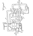
- FIG. 1 shows a system 10 for conditioning of the air supplied from a source (not shown) to a point of use (also not shown).
- the system 10 includes a primary heat exchanger 48, a secondary heat exchanger 42, and a component group 12 comprising a first heat exchanger 14, a second heat exchanger 16, a water trap or separator 18 and an ACM (air cycle machine) 20.
- the machine 20 comprises an air expansion turbine 22 and a centrifugal type air compressor 24, having their rotors mounted on a common shaft 72, together with a fan wheel 70.
- the heat exchangers 48, 42, 14 and 16 are, in the preferred form of the invention, of the type generally known in the art as a cross-flow-plate-fin device.
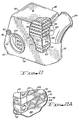
- the structure of the heat exchanger 14 is shown in more detail in Figures 2 and 2A.
- the heat exchanger 14 has a first group of passages for carrying a cold air flow from a cold air inlet plenum casing 26 to a cold air outlet plenum casing 28, and a second group of passages for carrying a warm air flow from a warm air inlet plenum casing 30 to a warm air outlet plenum casing 32, with heat transfer from the warm air flow to the cold air flow.
- compressed air is supplied from a source, such as the compressor of an engine of the aircraft, through an inlet duct 74 to a warm air inlet plenum casing 50 of the primary heat exchanger 48.
- the air then flows through warm air passages in the heat exchanger 48 to an outlet plenum casing 52, and is in the process cooled by heat transfer to a flow of cooling fluid through cold air passages in the heat exchanger 48.
- the cooling fluid is ambient air, and is supplied to the heat exchanger 48 through a duct 54.
- the flow of cooling air is produced by the ram effect, and controlled by door-type valves 64 and 66 positioned at the upper and lower ends 56 and 58 of the duct 54, and coupled to be adjusted by actuators 60 and 62.
- the flow of cooling air is produced by the fan wheel 70.
- This fan wheel is surrounded by a jet pump jacket 68, which is mounted within the duct 54 downstream of the primary heat exchanger 48, to form a jet pump for moving the cooling air.
- the cooled air then flows from the plenum casing 52 through a duct 76 to the compressor 24, where it is compressed further, and then flows through a duct 78 to a warm air inlet plenum casing 44 of the secondary heat exchanger 42.
- the compressed air flows through warm air passages to a warm air outlet plenum casing 46, while the flow of cooling air in the duct 54 passes through cold air passages in the heat exchanger 42 immediately before passing through the primary heat exchanger 48, and thereby cools the compressed air more or less back to the temperature prevailing at the entry to the compressor 24.
- the compressed and cooled air then flows through a duct 80 to a warm air inlet plenum casing 38 of the heat exchanger 16, and flows through warm air passages in the heat exchanger to a warm air outlet plenum casing 40.
- heat is transferred from the compressed air to air flowing in a further downstream part of the air flow path, as will become clear later on.
- the compressed air then flows through a duct 82 to the warm air inlet plenum 30 of the heat exchanger 14, and flows through the warm air passages of this heat exchanger to the outlet plenum 32, transferring heat to air flowing in an even further downstream part of the air flow path.
- the heat exchanger 14 cools the compressed air sufficiently far that condensation of the water (entrained in vapour form in the source air) occurs.
- the heat exchanger 14 may also be described as a condenser.
- the cooled air and entrained water droplets and mist resulting from the condensation then flow through a duct 83 to the water trap or separator 18, where nearly all of the condensed water is removed.
- the dry air then flows through a duct 84 to a cold air inlet plenum casing 34 of the heat exchanger 16, where, in the process of flowing through the heat exchanger to a cold air outlet plenum casing 36, the air absorbs the heat removed from the air on its first pass through the heat exchanger 16.
- the heat exchanger 16 could also be described as a reheater.
- the reheated air flows through a duct 86 to the inlet of the expansion turbine 22 where it is expanded and cooled to a point consistent with the energy supplied by the turbine 22 to the compressor 24 and the fan wheel 70.
- the turbine and compressor thus operate in what is generally known as bootstrap fashion.
- the air is conducted by a duct 88 to the plenum casing 26 of the condenser 14, where the air flows through the cold air passages to the plenum casing 28 and into a duct 90 leading to the point of usage.
- the air absorbs the heat which was removed from the air on its first pass through the heat exchanger; the amount of heat transferred is sufficient to condense nearly all the water vapour in the air, as described above.
- the water separated out by the water trap 18 may be fed through a pipe 51 to a nozzle 53, which injects the water into the duct 54 upstream of the heat exchangers 42 and 48.
- the heat exchanger or condenser 14 is also provided with a pipe coupling fixture 92 ( Figures 1 and 2) coupled with one end of a pipe 94 ( Figure 1), whose other end is coupled to the duct 78, to divert a flow of hot compressed air from the delivery of the compressor 24 to the chamber defined by a plenum casing 96, into which the pipe fixture 92 leads.
- the heat exchanger comprises two identical core sections;98 and 100 ( Figure 2), which are spaced apart so as to leave a free passage 102 having side walls 104 and 106, and leading from the cold-air inlet plenum 26 to the cold air outlet plenum 28.
- Each of the core elements 98 and 100 comprises a plurality of plates 108 ( Figure 2A), spaced apart at their edges by header bars 110 and 112. Of the various spaces between the plates 108, alternate ones form the cold air passages, while the remaining ones form the warm air passages.
- the cold air passages are bounded along the edges of the plates 108 by the header bars 110, and contain fins 114 which have corrugations extending parallel to the cold air flow direction; similarly, the warm air passages are bounded by the header bars 112, and contain corrugated fins 116.
- the plates which bound the core sections 98 and 100, where these adjoin the free passage 102, are similar to the plates 108, but are indicated by the reference numerals 128 and 126 respectively.
- the fins may for example be secured to the adjacent plate surfaces by brazing. While the fins 114 and 116 have been shown as having a substantially triangular section having apex contact with the plates 108, 126 and 128, it will be understood that fins of other configurations may be employed.
- Fittings 118, 120, 122 and 124 are provided in the walls of the plenum casings 26, 28, 30 and 32 respectively, to allow the ducts 88, 90, 82 and 83 to be coupled to these casings.
- the header bars 112 along the edges of the warm air passages are hollow to provide passages leading from the chamber formed by the plenum casing 96 to the chamber formed by the warm air outlet plenum casing 32, so that the heated air from the compressor 24 provides heating of the bars 112 to prevent icing at the entrance to the cold air passages.
- the air leaving the hollow header bars 112 then mixes with the cooled air flowing from the warm air passages.
- the passage 102 provides a bypass around the cold air passages; at least a portion of the expanded and cooled air furnished at the discharge of the turbine 22 reaches the point of use through this bypass. It has been discovered that if about one-third of the total air flow is directed through the bypass duct, sufficient cooling of the air in the warm air passages to provide condensation can still be obtained.
- FIG. 1 The orientation and relationship of the various elements of the condenser 14 of Figures 1, 2 and 2A may be more clearly understood by reference to the schematic representation of Figure 3, which uses the same reference numerals as in Figures 1, 2 and 2A.
- the pair of ducts schematically depicted on Figure 3 at 83a and 83b correspond to the duct 83 of Figure 1.
- a flow control valve could be disposed in the bypass (or in the parallel cold air passages), to control the working fluid flow therethrough, if desired.
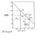
- the increase of cooling capacity with a decrease of the air delivery temperature is shown in Figure 4.
- the vertical dashed line 170 extends from the abscissa at about the 2°C point which is the previous lower limit of air delivery temperature.
- the horizontal dashed line 172 which extends from the ordinate at the cooling capacity point of 1.0 (arbitrary units), intersects the line 170 at a point 174 lying on a line 176 whose slope is derived from the equation for cooling capacity Q given above.
- relatively minor decreases in the air delivery temperature can result in relatively large percentage increases of cooling capacity from the same refrigeration capacity. For example, if the delivery temperature can be lowered to about -B°C, the cooling capacity increases by about 40%, as seen from dashed lines 178, 180 intersecting at point 182 on line 17-6.
Landscapes
- Engineering & Computer Science (AREA)
- Physics & Mathematics (AREA)
- Thermal Sciences (AREA)
- Mechanical Engineering (AREA)
- General Engineering & Computer Science (AREA)
- Health & Medical Sciences (AREA)
- General Health & Medical Sciences (AREA)
- Pulmonology (AREA)
- Aviation & Aerospace Engineering (AREA)
- Heat-Exchange Devices With Radiators And Conduit Assemblies (AREA)
Applications Claiming Priority (2)
| Application Number | Priority Date | Filing Date | Title |
|---|---|---|---|
| US41451 | 1979-05-22 | ||
| US06/041,451 US4352273A (en) | 1979-05-22 | 1979-05-22 | Fluid conditioning apparatus and system |
Publications (3)
| Publication Number | Publication Date |
|---|---|
| EP0019492A2 true EP0019492A2 (de) | 1980-11-26 |
| EP0019492A3 EP0019492A3 (en) | 1982-01-20 |
| EP0019492B1 EP0019492B1 (de) | 1986-04-09 |
Family
ID=21916577
Family Applications (1)
| Application Number | Title | Priority Date | Filing Date |
|---|---|---|---|
| EP80301690A Expired EP0019492B1 (de) | 1979-05-22 | 1980-05-21 | Gasversorgungsanlage, insbesondere Luftversorgungsanlage |
Country Status (5)
| Country | Link |
|---|---|
| US (1) | US4352273A (de) |
| EP (1) | EP0019492B1 (de) |
| JP (1) | JPS6027915B2 (de) |
| CA (1) | CA1124072A (de) |
| DE (1) | DE3071530D1 (de) |
Cited By (13)
| Publication number | Priority date | Publication date | Assignee | Title |
|---|---|---|---|---|
| DE3126061A1 (de) * | 1980-07-07 | 1982-04-29 | Normalair-Garrett (Holdings) Ltd., Yeovil, Somerset | Luftzyklus-klimaanlage |
| FR2555131A1 (fr) * | 1983-11-18 | 1985-05-24 | Teledyne Ind | Appareil et procede de climatisation d'aeronefs en stationnement |
| EP0147987A3 (en) * | 1983-12-16 | 1986-08-20 | The Garrett Corporation | Turbine-heat exchanger assembly |
| WO1991000213A1 (en) * | 1989-06-23 | 1991-01-10 | Allied-Signal Inc. | Ecs with advanced air cycle machine |
| WO1999024318A1 (en) * | 1997-11-11 | 1999-05-20 | Alliedsignal Inc. | Two spool environmental control system |
| FR2796918A1 (fr) | 1999-07-30 | 2001-02-02 | Liebherr Aerospace Gmbh | Procede et systeme de climatisation pour des cabines d'avion |
| US6199387B1 (en) | 1999-07-30 | 2001-03-13 | Liebherr-Aerospace Lindenberg Gmbh | Air-conditioning system for airplane cabin |
| EP1176090A1 (de) * | 2000-07-26 | 2002-01-30 | Liebherr-Aerospace Lindenberg GmbH | Klimatisierungssystem für Flugzeuge |
| EP2757343A1 (de) * | 2013-01-21 | 2014-07-23 | Hamilton Sundstrand Corporation | Wärmetauscherüberbrückung für Belastung unter dem Gefrierpunkt |
| FR3023366A1 (fr) * | 2014-07-04 | 2016-01-08 | Snecma | Echangeur thermique pour un fluide susceptible de former des particules de givre |
| FR3093325A1 (fr) * | 2019-03-01 | 2020-09-04 | Liebherr-Aerospace Toulouse Sas | Système de conditionnement d’air d’une cabine d’aéronef comprenant des moyens de réchauffage de l’eau récoltée par la boucle d’extraction d’eau |
| US20230079592A1 (en) * | 2021-09-16 | 2023-03-16 | Gulfstream Aerospace Corporation | Vehicle, environmental control system, and method for operating an environmental control system |
| US12653922B2 (en) | 2023-09-01 | 2026-06-16 | B/E Aerospace, Inc. | Aircraft lavatory with integrated air ionizer |
Families Citing this family (44)
| Publication number | Priority date | Publication date | Assignee | Title |
|---|---|---|---|---|
| US4835977A (en) * | 1983-11-18 | 1989-06-06 | Teledyne Industries, Inc. | Apparatus and method of air-conditioning parked aircraft |
| US4580406A (en) * | 1984-12-06 | 1986-04-08 | The Garrett Corporation | Environmental control system |
| US4665973A (en) * | 1984-12-21 | 1987-05-19 | The Garrett Corporation | Environmental control system |
| US4844151A (en) * | 1986-12-23 | 1989-07-04 | Sundstrand Corporation | Heat exchanger apparatus |
| FI79409C (fi) * | 1987-07-13 | 1989-12-11 | Pentti Raunio | Foerfarande foer konstruering av en vaermevaexlare jaemte enligt foerfarandet konstruerad vaermevaexlare. |
| US4883117A (en) * | 1988-07-20 | 1989-11-28 | Sundstrand Corporation | Swirl flow heat exchanger with reverse spiral configuration |
| US5214935A (en) * | 1990-02-20 | 1993-06-01 | Allied-Signal Inc. | Fluid conditioning apparatus and system |
| EP0515575A1 (de) * | 1990-02-20 | 1992-12-02 | AlliedSignal Inc. | Vorrichtung und verfahren zur konditionierung einer flüssigkeit |
| US5025642A (en) * | 1990-02-20 | 1991-06-25 | Allied-Signal Inc. | Fluid conditioning apparatus and system |
| US5086622A (en) * | 1990-08-17 | 1992-02-11 | United Technologies Corporation | Environmental control system condensing cycle |
| US5133194A (en) * | 1991-02-04 | 1992-07-28 | United Technologies Corporation | Air cycle machine and fan inlet/diffuser therefor |
| AU5683294A (en) * | 1992-11-27 | 1994-06-22 | Pneumo Abex Corporation | Thermoelectric device for heating and cooling air for human use |
| US5383335A (en) * | 1993-10-19 | 1995-01-24 | Pneumo Abex Corporation | Method and apparatus for supplying preconditioned air to a parked aircraft |
| US5497615A (en) * | 1994-03-21 | 1996-03-12 | Noe; James C. | Gas turbine generator set |
| IL114613A (en) * | 1995-07-16 | 1999-09-22 | Tat Ind Ltd | Parallel flow condenser heat exchanger |
| EP0990111B1 (de) | 1997-05-30 | 2004-03-03 | Honeywell International Inc. | Metallwärmetauscher auf titanbasis und verfahren zu dessen herstellung |
| US6735953B1 (en) | 1997-12-22 | 2004-05-18 | Allied Signal Inc. | Turbomachine-driven environmental control system |
| DE10015570B4 (de) * | 2000-03-29 | 2007-11-22 | Airbus Deutschland Gmbh | Anordnung zur Zwangsführung eines Kühlluftstromes innerhalb eines Kühlaggregates für ein Verkehrsflugzeug |
| DE10119433C1 (de) | 2001-04-20 | 2002-08-22 | Liebherr Aerospace Gmbh | Stauluftkanal für eine Flugzeugklimaanlage |
| DE10247335B3 (de) * | 2002-10-10 | 2004-04-08 | Liebherr-Aerospace Lindenberg Gmbh | Kondensor |
| EP1570220B1 (de) * | 2002-12-02 | 2008-03-19 | Lg Electronics Inc. | Wärmetauscher einer lüftungsanlage |
| US20050189342A1 (en) * | 2004-02-23 | 2005-09-01 | Samer Kabbani | Miniature fluid-cooled heat sink with integral heater |
| US7334422B2 (en) * | 2005-11-29 | 2008-02-26 | Hamilton Sundstrand Corporation | Cabin air conditioning system with liquid cooling for power electronics |
| US8656727B2 (en) * | 2008-04-08 | 2014-02-25 | The Boeing Company | Evaporative cooling for an aircraft subsystem |
| JP5343511B2 (ja) * | 2008-10-30 | 2013-11-13 | 株式会社島津製作所 | 熱交換器 |
| US8490419B2 (en) * | 2009-08-20 | 2013-07-23 | United States Thermoelectric Consortium | Interlocked jets cooling method and apparatus |
| EP2413045B1 (de) * | 2010-07-30 | 2014-02-26 | Grundfos Management A/S | Wärmetauschereinheit |
| US9267414B2 (en) * | 2010-08-26 | 2016-02-23 | Modine Manufacturing Company | Waste heat recovery system and method of operating the same |
| DE102011105968A1 (de) * | 2011-06-29 | 2013-01-03 | Airbus Operations Gmbh | Stauluftkanalanordnung und Flugzeugklimaanlage |
| US9631834B2 (en) * | 2011-11-21 | 2017-04-25 | Lennox Industries Inc. | Dehumidifier having split condenser configuration |
| US20140352933A1 (en) * | 2013-05-28 | 2014-12-04 | Hamilton Sundstrand Corporation | Core assembly for a heat exchanger and method of assembling |
| US11459110B2 (en) * | 2016-04-22 | 2022-10-04 | Hamilton Sunstrand Corporation | Environmental control system utilizing two pass secondary heat exchanger and cabin pressure assist |
| US11255615B2 (en) * | 2018-01-23 | 2022-02-22 | Hamilton Sundstrand Corporation | Heat exchanger flexible manifold |
| US10995997B2 (en) * | 2018-06-26 | 2021-05-04 | Hamilton Sunstrand Corporation | Heat exchanger with integral features |
| FR3093356B1 (fr) * | 2019-03-01 | 2021-02-12 | Liebherr Aerospace Toulouse Sas | Échangeur de refroidissement d’un air primaire chaud par un air secondaire froid et système de conditionnement d’air équipé d’un tel échangeur |
| CN110094903B (zh) * | 2019-06-06 | 2024-05-21 | 珠海格力电器股份有限公司 | 空调及分流器 |
| US11221186B2 (en) * | 2019-07-18 | 2022-01-11 | Hamilton Sundstrand Corporation | Heat exchanger closure bar with shield |
| CN110816852B (zh) * | 2019-11-27 | 2022-11-22 | 中国航空工业集团公司沈阳飞机设计研究所 | 一种压差感受式冷凝器防冻堵装置及方法 |
| US11668531B2 (en) * | 2020-12-04 | 2023-06-06 | Hamilton Sundstrand Corporation | Subfreezing heat exchanger with separate melt fluid |
| JP7534976B2 (ja) * | 2021-02-05 | 2024-08-15 | 三菱重工業株式会社 | 熱交換コア及び熱交換器 |
| FR3126444B1 (fr) | 2021-08-26 | 2024-11-29 | Safran Nacelles | Système de refroidissement d’un fluide réfrigérant pour aéronef comportant un dispositif de chauffage sécuritaire et procédé d’utilisation d’un tel système |
| US12311300B2 (en) * | 2022-08-03 | 2025-05-27 | Hamilton Sundstrand Corporation | Mid-pressure water separation for environmental control system |
| FR3155293B1 (fr) * | 2023-11-14 | 2026-02-13 | Liebherr Aerospace Toulouse Sas | Échangeur de chaleur comprenant au moins une plaque comprenant au moins un canal de pulvérisation d’eau, système de refroidissement et procédé de fabrication |
| US12680739B2 (en) | 2024-05-31 | 2026-07-14 | Rtx Corporation | Deicing and icing prevention system for advance cycle condensers |
Family Cites Families (21)
| Publication number | Priority date | Publication date | Assignee | Title |
|---|---|---|---|---|
| US1914604A (en) * | 1930-01-24 | 1933-06-20 | Foster Wheeler Corp | Air preheater |
| US2077315A (en) * | 1933-08-29 | 1937-04-13 | Ewing Sydney Edward Thacker | De-vaporizing compressed air |
| CH261037A (fr) * | 1942-12-14 | 1949-04-15 | Westinghouse Freins & Signaux | Installation de conditionnement d'air pour enceintes, notamment pour cabines d'aéronef. |
| US2494785A (en) * | 1946-02-14 | 1950-01-17 | Stewart Warner Corp | Heat exchanger and combustion chamber construction for internal-combustion air heaters |
| US2585570A (en) * | 1946-07-29 | 1952-02-12 | Lockheed Aircraft Corp | Aircraft pressurizing and cooling system |
| US2453923A (en) * | 1946-08-20 | 1948-11-16 | Douglas Aircraft Co Inc | Aircraft cooling by air turbine means |
| US2614815A (en) * | 1947-01-20 | 1952-10-21 | Bristol Aeroplane Co Ltd | Aircraft cabin pressurizing and air conditioning apparatus |
| US2602307A (en) * | 1949-10-31 | 1952-07-08 | Collison George Chester | Air-conditioning method and apparatus therefor |
| US2867989A (en) * | 1955-02-17 | 1959-01-13 | United Aircraft Corp | Water separator de-icing control |
| US2829505A (en) * | 1955-04-27 | 1958-04-08 | Lockheed Aircraft Corp | Systems for preventing ice formation |
| US2979916A (en) * | 1956-04-30 | 1961-04-18 | Garrett Corp | Humidity control system |
| US2902836A (en) * | 1957-03-29 | 1959-09-08 | Garrett Corp | Regenerative air conditioning system with bleed conservation control |
| US3093470A (en) * | 1960-06-28 | 1963-06-11 | United Aircraft Corp | Co2 freezeout system |
| FR1325852A (fr) * | 1962-03-23 | 1963-05-03 | Rateau Soc | Dispositif de dessication pour gaz |
| US3226948A (en) * | 1964-10-07 | 1966-01-04 | Ingersoll Rand Co | Dehumidifying apparatus |
| US3587243A (en) * | 1969-05-29 | 1971-06-28 | Grumman Aerospace Corp | Precondensing regenerative air cycle system |
| US3623332A (en) * | 1970-03-31 | 1971-11-30 | United Aircraft Prod | Air cycle air conditioning system and method |
| DE2336500C3 (de) * | 1973-07-18 | 1979-09-06 | Vereinigte Flugtechnische Werkefokker Gmbh, 2800 Bremen | Vorrichtung zur Klimatisierung von Luftfahrzeugkabinen |
| US4209993A (en) * | 1978-03-06 | 1980-07-01 | United Technologies Corp. | Efficiency air cycle environmental control system |
| US4198830B1 (en) * | 1978-07-03 | 1995-04-18 | Garrett Corp | Fluid conditioning apparatus and system |
| US4246963A (en) * | 1978-10-26 | 1981-01-27 | The Garrett Corporation | Heat exchanger |
-
1979
- 1979-05-22 US US06/041,451 patent/US4352273A/en not_active Expired - Lifetime
-
1980
- 1980-04-23 CA CA350,461A patent/CA1124072A/en not_active Expired
- 1980-05-16 JP JP55064203A patent/JPS6027915B2/ja not_active Expired
- 1980-05-21 DE DE8080301690T patent/DE3071530D1/de not_active Expired
- 1980-05-21 EP EP80301690A patent/EP0019492B1/de not_active Expired
Cited By (21)
| Publication number | Priority date | Publication date | Assignee | Title |
|---|---|---|---|---|
| DE3126061A1 (de) * | 1980-07-07 | 1982-04-29 | Normalair-Garrett (Holdings) Ltd., Yeovil, Somerset | Luftzyklus-klimaanlage |
| FR2555131A1 (fr) * | 1983-11-18 | 1985-05-24 | Teledyne Ind | Appareil et procede de climatisation d'aeronefs en stationnement |
| DE3442001A1 (de) * | 1983-11-18 | 1985-05-30 | Teledyne Industries, Inc., Los Angeles, Calif. | Einrichtung und verfahren zum klimatisieren von geparkten flugzeugen |
| GB2150278A (en) * | 1983-11-18 | 1985-06-26 | Teledyne Ind | Cooling cabins of parked aircraft |
| AU575355B2 (en) * | 1983-11-18 | 1988-07-28 | Magnetek Power Technology Systems | Apparatus and method of air conditioning parked aircraft |
| EP0147987A3 (en) * | 1983-12-16 | 1986-08-20 | The Garrett Corporation | Turbine-heat exchanger assembly |
| EP0150599B1 (de) * | 1983-12-16 | 1989-04-26 | AlliedSignal Inc. | Luftkreislauf-Kälteanlage |
| WO1991000213A1 (en) * | 1989-06-23 | 1991-01-10 | Allied-Signal Inc. | Ecs with advanced air cycle machine |
| WO1999024318A1 (en) * | 1997-11-11 | 1999-05-20 | Alliedsignal Inc. | Two spool environmental control system |
| US6199387B1 (en) | 1999-07-30 | 2001-03-13 | Liebherr-Aerospace Lindenberg Gmbh | Air-conditioning system for airplane cabin |
| FR2796918A1 (fr) | 1999-07-30 | 2001-02-02 | Liebherr Aerospace Gmbh | Procede et systeme de climatisation pour des cabines d'avion |
| DE19935918B4 (de) * | 1999-07-30 | 2006-08-31 | Liebherr-Aerospace Lindenberg Gmbh | Klimatisierungssystem für Flugzeugkabinen |
| EP1176090A1 (de) * | 2000-07-26 | 2002-01-30 | Liebherr-Aerospace Lindenberg GmbH | Klimatisierungssystem für Flugzeuge |
| EP2757343A1 (de) * | 2013-01-21 | 2014-07-23 | Hamilton Sundstrand Corporation | Wärmetauscherüberbrückung für Belastung unter dem Gefrierpunkt |
| US9745069B2 (en) | 2013-01-21 | 2017-08-29 | Hamilton Sundstrand Corporation | Air-liquid heat exchanger assembly having a bypass valve |
| FR3023366A1 (fr) * | 2014-07-04 | 2016-01-08 | Snecma | Echangeur thermique pour un fluide susceptible de former des particules de givre |
| FR3093325A1 (fr) * | 2019-03-01 | 2020-09-04 | Liebherr-Aerospace Toulouse Sas | Système de conditionnement d’air d’une cabine d’aéronef comprenant des moyens de réchauffage de l’eau récoltée par la boucle d’extraction d’eau |
| WO2020178504A3 (fr) * | 2019-03-01 | 2020-11-19 | Liebherr-Aerospace Toulouse Sas | Système de conditionnement d'air d'une cabine d'aéronef comprenant des moyens de réchauffage de l'eau récoltée par la boucle d'extraction d'eau |
| CN113544059A (zh) * | 2019-03-01 | 2021-10-22 | 利勃海尔-航空航天图卢兹有限公司 | 用于飞行器舱室的空调系统,包括用于加热通过水提取回路收集的水的装置 |
| US20230079592A1 (en) * | 2021-09-16 | 2023-03-16 | Gulfstream Aerospace Corporation | Vehicle, environmental control system, and method for operating an environmental control system |
| US12653922B2 (en) | 2023-09-01 | 2026-06-16 | B/E Aerospace, Inc. | Aircraft lavatory with integrated air ionizer |
Also Published As
| Publication number | Publication date |
|---|---|
| US4352273A (en) | 1982-10-05 |
| DE3071530D1 (en) | 1986-05-15 |
| CA1124072A (en) | 1982-05-25 |
| EP0019492B1 (de) | 1986-04-09 |
| JPS55165489A (en) | 1980-12-23 |
| EP0019492A3 (en) | 1982-01-20 |
| JPS6027915B2 (ja) | 1985-07-02 |
Similar Documents
| Publication | Publication Date | Title |
|---|---|---|
| EP0019492B1 (de) | Gasversorgungsanlage, insbesondere Luftversorgungsanlage | |
| EP3514065B1 (de) | Umweltkontrollsystem für flugzeug | |
| EP0772545B1 (de) | Regenerativer kondensierkreislauf | |
| EP0035909B1 (de) | Klimaanlagensystem | |
| CA2044292C (en) | Environmental control system condensing cycle | |
| EP3945023B1 (de) | Flugzeugklimaregelungssystem | |
| CA2416471A1 (en) | Air conditioning system | |
| CN108357681B (zh) | 具有两个泄放/流出热交换器的集成分包布置中的高级环境控制系统 | |
| EP3945029B1 (de) | Flugzeugklimaregelungssystem | |
| EP4292937B1 (de) | Durch stauluftturbine angetriebener kabinenluftverdichter | |
| EP4036013B1 (de) | Raumluftarchitektur mit einer einzigen acm ohne umgebungsturbine | |
| US20020088245A1 (en) | Air-conditioning system for aircraft | |
| EP3835208B1 (de) | Bootstrap-druckluftklimaanlage mit kaltdampf-leistungsturbine | |
| US12162607B2 (en) | Environmental control system for supersonic commercial aircraft | |
| EP4147973B1 (de) | Trimmluftwärmetauscher für eine klimaanlage | |
| EP4585879A2 (de) | Funktion für einen untergefrierwärmetauscher | |
| US20240410625A1 (en) | Regeneration using liquid loop of environmental control system | |
| US11767121B2 (en) | Optimized environmental control system for military aircraft | |
| EP4265521B1 (de) | Klimaregelungssystem mit luftbetriebener pumpe | |
| EP4331991A1 (de) | Klimaregelungssystem mit niedrigem einlassdruck | |
| US12595978B2 (en) | Drain system for ECS water collection | |
| EP4299444A1 (de) | Umweltkontrollsystem mit geteilter regeneration | |
| US20250334354A1 (en) | Contoured inlet manifold for subfreezing heat exchanger | |
| EP4725840A1 (de) | Niederdruckluftkreislauf-klimaanlagensteuersystem | |
| US20250304263A1 (en) | Environmental control system using architecture with turbines in series and a mid-pressure water separator |
Legal Events
| Date | Code | Title | Description |
|---|---|---|---|
| PUAI | Public reference made under article 153(3) epc to a published international application that has entered the european phase |
Free format text: ORIGINAL CODE: 0009012 |
|
| AK | Designated contracting states |
Designated state(s): DE FR GB NL |
|
| 17P | Request for examination filed |
Effective date: 19810518 |
|
| PUAL | Search report despatched |
Free format text: ORIGINAL CODE: 0009013 |
|
| AK | Designated contracting states |
Designated state(s): DE FR GB NL |
|
| GRAA | (expected) grant |
Free format text: ORIGINAL CODE: 0009210 |
|
| AK | Designated contracting states |
Kind code of ref document: B1 Designated state(s): DE FR GB NL |
|
| REF | Corresponds to: |
Ref document number: 3071530 Country of ref document: DE Date of ref document: 19860515 |
|
| ET | Fr: translation filed | ||
| PLBE | No opposition filed within time limit |
Free format text: ORIGINAL CODE: 0009261 |
|
| STAA | Information on the status of an ep patent application or granted ep patent |
Free format text: STATUS: NO OPPOSITION FILED WITHIN TIME LIMIT |
|
| 26N | No opposition filed | ||
| PGFP | Annual fee paid to national office [announced via postgrant information from national office to epo] |
Ref country code: GB Payment date: 19980430 Year of fee payment: 19 |
|
| PGFP | Annual fee paid to national office [announced via postgrant information from national office to epo] |
Ref country code: NL Payment date: 19990322 Year of fee payment: 20 |
|
| PGFP | Annual fee paid to national office [announced via postgrant information from national office to epo] |
Ref country code: FR Payment date: 19990504 Year of fee payment: 20 |
|
| PG25 | Lapsed in a contracting state [announced via postgrant information from national office to epo] |
Ref country code: GB Free format text: LAPSE BECAUSE OF NON-PAYMENT OF DUE FEES Effective date: 19990521 |
|
| PGFP | Annual fee paid to national office [announced via postgrant information from national office to epo] |
Ref country code: DE Payment date: 19990531 Year of fee payment: 20 |
|
| GBPC | Gb: european patent ceased through non-payment of renewal fee |
Effective date: 19990521 |
|
| PG25 | Lapsed in a contracting state [announced via postgrant information from national office to epo] |
Ref country code: NL Free format text: LAPSE BECAUSE OF EXPIRATION OF PROTECTION Effective date: 20000521 |
|
| NLV7 | Nl: ceased due to reaching the maximum lifetime of a patent |
Effective date: 20000521 |