EP0019967A1 - Installation de déchargement de wagons-trémies et similaires - Google Patents
Installation de déchargement de wagons-trémies et similaires Download PDFInfo
- Publication number
- EP0019967A1 EP0019967A1 EP80200454A EP80200454A EP0019967A1 EP 0019967 A1 EP0019967 A1 EP 0019967A1 EP 80200454 A EP80200454 A EP 80200454A EP 80200454 A EP80200454 A EP 80200454A EP 0019967 A1 EP0019967 A1 EP 0019967A1
- Authority
- EP
- European Patent Office
- Prior art keywords
- deflectors
- hopper
- installation according
- installation
- strip
- Prior art date
- Legal status (The legal status is an assumption and is not a legal conclusion. Google has not performed a legal analysis and makes no representation as to the accuracy of the status listed.)
- Granted
Links
- 238000009434 installation Methods 0.000 title claims abstract description 20
- 229910001220 stainless steel Inorganic materials 0.000 claims description 2
- 239000010935 stainless steel Substances 0.000 claims description 2
- 238000000605 extraction Methods 0.000 claims 1
- 238000007599 discharging Methods 0.000 abstract description 2
- 238000011144 upstream manufacturing Methods 0.000 abstract 1
- 239000003245 coal Substances 0.000 description 10
- 239000000463 material Substances 0.000 description 5
- 230000015572 biosynthetic process Effects 0.000 description 2
- 230000002787 reinforcement Effects 0.000 description 2
- OKTJSMMVPCPJKN-UHFFFAOYSA-N Carbon Chemical compound [C] OKTJSMMVPCPJKN-UHFFFAOYSA-N 0.000 description 1
- 229910052799 carbon Inorganic materials 0.000 description 1
- OKTJSMMVPCPJKN-YPZZEJLDSA-N carbon-10 atom Chemical compound [10C] OKTJSMMVPCPJKN-YPZZEJLDSA-N 0.000 description 1
- 239000000571 coke Substances 0.000 description 1
- 238000006073 displacement reaction Methods 0.000 description 1
- 230000002349 favourable effect Effects 0.000 description 1
- 238000012986 modification Methods 0.000 description 1
- 230000004048 modification Effects 0.000 description 1
- 239000011150 reinforced concrete Substances 0.000 description 1
- 239000004576 sand Substances 0.000 description 1
- XLYOFNOQVPJJNP-UHFFFAOYSA-N water Substances O XLYOFNOQVPJJNP-UHFFFAOYSA-N 0.000 description 1
Images

Classifications
-
- B—PERFORMING OPERATIONS; TRANSPORTING
- B65—CONVEYING; PACKING; STORING; HANDLING THIN OR FILAMENTARY MATERIAL
- B65G—TRANSPORT OR STORAGE DEVICES, e.g. CONVEYORS FOR LOADING OR TIPPING, SHOP CONVEYOR SYSTEMS OR PNEUMATIC TUBE CONVEYORS
- B65G67/00—Loading or unloading vehicles
- B65G67/02—Loading or unloading land vehicles
- B65G67/24—Unloading land vehicles
-
- B—PERFORMING OPERATIONS; TRANSPORTING
- B65—CONVEYING; PACKING; STORING; HANDLING THIN OR FILAMENTARY MATERIAL
- B65D—CONTAINERS FOR STORAGE OR TRANSPORT OF ARTICLES OR MATERIALS, e.g. BAGS, BARRELS, BOTTLES, BOXES, CANS, CARTONS, CRATES, DRUMS, JARS, TANKS, HOPPERS, FORWARDING CONTAINERS; ACCESSORIES, CLOSURES, OR FITTINGS THEREFOR; PACKAGING ELEMENTS; PACKAGES
- B65D88/00—Large containers
- B65D88/26—Hoppers, i.e. containers having funnel-shaped discharge sections
Definitions
- the present invention relates to an installation for unloading hopper wagons and the like, such as those used for example for the transport of coal, coke, ore, etc.
- unloading facilities consist of pits located under the tracks and in which are housed devices for discharging unloaded products.
- the object of the present invention is to remedy these drawbacks by proposing an installation for unloading coal from hopper wagons, installation of the type consisting of a pit, located below a railroad track, containing a hopper. and a means for extracting coal from the bottom of the hopper, characterized in that said means for extracting coal is a smooth conveyor belt and in that deflectors are provided in said hopper, these deflecters being oblique with respect to the direction of displacement of said strip.
- the slope or the inclination of the walls of said hopper and said deflectors corresponds substantially to the natural slope of the spilled material.
- the invention also provides that the distance, seen in the direction of movement of the strip, between the lower ends of the deflectors and said strip, is increasing and that the mutual distance between said deflectors corresponds substantially to the double mutual distance between the crosspieces of the railway track.
- the sleepers of the railway track form an integral part of the structure of said pit and are provided, over at least part of their length, with a dihedral cap.
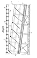
- FIG. 1 In FIG. 1 is shown a part of a train of hopper wagons 1, stopped on the railway track 2, the hopper wagon 3 being at the height of the unloading installation 4 ..
- This installation comprises a pit 5, generally made of reinforced concrete, a hopper 6, supported by a frame of beams 7, fixed to the walls of the pit 5 and a smooth conveyor belt 8 in the bottom of said hopper 6 and carried by a frame of beams 9, connected to the frame 7 and bearing on the floor of the pit 5.
- the inclination of the walls of the hopper 6 corresponds substantially to the natural slope of the spilled material 10 and is of the order of 50 ° for coal.
- Deflectors 11, supported by reinforcements 12 and connected to the reinforcement 7, are provided perpendicular to the interior walls of the hopper 6 and obliquely to the direction of movement of the strip 8, their inclination also corresponding to the natural slope of the spilled material 10.
- These baffles 11 are mutually parallel and are spaced from one another by a distance corresponding substan - tially to twice the distance between two adjacent cross members 13 of the track 2.
- the walls of the hopper 6 and the deflectors 11 are preferably made of stainless steel.
- the sleepers 13 are covered with coal, these are provided, over at least part of their length, with a cap 15 in the form of a dihedron.
- the ends 16 of the crosspieces 13 are secured to the frame of the walls of the pit 5.
- the installation described above as a practical embodiment of the present invention makes it possible to extract the coal from the pit continuously and evenly, even during the unloading of the wagons 3.
- the arrangement and the inclination of the walls of the hopper 6 and the deflectors 11, relative to the conveyor belt 8, make it possible to bring the coal to said strip 8 in a regular manner and without the formation of bridges.
- the pressure of the carbon 10 is largely supported by the oblique deflectors 11, the pressure and the friction on the strip 8 will be minimal, and, therefore, the power for its drive must not be very high.
- the depth of the pit 5 can be reduced considerably compared to the state of the art, since the strip 8 takes up only a small amount of space and the coal is extracted regularly and continuously, the coal not having to be accumulated in the pit. Reducing the dimensions of the cellar also solves the water problem and has a favorable impact on the cost price of the installation.
- the installation according to the invention can also be used for the unloading of other materials, such as for example sand, gravel, etc., the inclination of the walls of the hopper and deflectors being chosen by function of the natural slope of the materials discharged in this case.
Landscapes
- Engineering & Computer Science (AREA)
- Mechanical Engineering (AREA)
- Aviation & Aerospace Engineering (AREA)
- Filling Or Emptying Of Bunkers, Hoppers, And Tanks (AREA)
- Auxiliary Methods And Devices For Loading And Unloading (AREA)
- Loading Or Unloading Of Vehicles (AREA)
- Agricultural Chemicals And Associated Chemicals (AREA)
Abstract
Description
- La présente invention concerne une installation de déchargement de wagons-trémies et similaires, tels qu'utilisés par exemple pour le transport de houille, coke, minerai etc., ...
- Actuellement, les installations de déchargement sont constituées par des fosses situées sous les voies et dans lesquelles sont logés des dispositifs d'évacuation des produits déchargés.
- La grande contenance des wagons-trémies et leur déchargement massif, axial ou latéral, peuvent causer.des problèmes de par la formation de ponts dans les fosses, au-dessus des dispositifs d'évacuation. Pour cette raison, ces derniers ont toujours été complexes, robustes et encombrants. Outre leur coût propre, leur encombrement nécessite des fosses relativement profondes donc onéreuses.
- La présente invention a pour but de remédier à ces inconvénients en proposant une installation de déchargement de charbon à partir de wagons-trémies, installation du type constitué par une fosse, située au-dessous d'une voie de chemin de fer, contenant une trémie et un moyen d'extraction du charbon dans le fond de la trémie, caractérisée en ce que ledit moyen d'extraction du charbon est une bande transporteuse lisse et en ce que des déflecteurs sont prévus dans ladite trémie, ces déflecteirs étant obliques par rapport à la direction de déplacement de ladite bande.
- Selon l'invention, la pente ou l'inclinaison des parois de ladite trémie et desdits déflecteurs correspond substantiellement au talus naturel du matériau déversé. L'invention prévoit également que la distance, vu dans le sens de déplacement de la bande, entre les extrémités inférieures des déflecteurs et ladite bande, va en croissant et que la distance mutuelle entre lesdits déflecteurs correspond substantiellement à la double distance mutuelle entre les traverses de la voie de chemin de fer.
- Selon une exécution préférée de l'invention, les traverses de la voie de chemin de fer font parties intégrantes de la structure de ladite fosse et sont pourvues, sur une partie au moins de leur longueur, d'une coiffe en forme de dièdre.
- Afin de mieux faire comprendre l'objet de la présente invention, celle-ci sera décrite plus en détail ci-dessous à l'aide d'un exemple de réalisation pratique, non-limitatif, représenté dans les dessins annexés, dans lesquels :
- la figure 1 représente, en vue latérale et partiellement en coupe, l'ensemble d'une installation suivant l'invention;
- la figure 2 représente une vue selon la coupe II-II dans
- la figure 1; et
- la figure 3 représente une vue selon la coupe III-III. dans la figure 2.
- A la figure 1 est représentée une partie d'une rame de wagons-trémies 1, arrêtée sur la voie de chemin de fer 2, le wagon- trémie 3 se trouvant à la hauteur de l'installation de déchargement 4..
- Cette installation comporte une fosse 5, généralement réalisée en béton armé, une trémie 6, supportée par une armature de poutres 7, fixée aux parois de la fosse 5 et une bande transporteuse lisse 8 dans le fond de ladite trémie 6 et portée par une armature de poutres 9, reliée à l'armature 7 et prenant appui sur le sol de la fosse 5.
- L'inclinaison des parois de la trémie 6 correspond substantiellement au talus naturel du matériau déversé 10 et est de l'ordre de 50° pour le charbon.
- Des déflecteurs 11, supportés par des armatures 12 et reliés à l'armature 7, sont prévus perpendiculairement aux parois intérieures de la trémie 6 et en oblique par rapport à la direction de déplacement de la bande 8, leur inclinaison correspondant également au talus naturel du matériau déversé 10. Ces déflecteurs 11 sont mutuellement parallèles et sont espacés l'un de l'autre d'une distance correspondant substan- tiellement au double de la distance entre deux traverses adjacentes 13 de la voie 2.
- La distance entre les extrémités inférieures 14 des déflecteurs 11 et la bande 8, vu dans le sens du déplacement de ladite bande 8, va en croissant afin d'obtenir une couche de charbon régulièrement laminée sur la bande 8.
- Les parois de la trémie 6 et les déflecteurs 11 sont de préférence réalisés en acier inoxydable.
- Afin d'éviter que, lors du déchargement du wagon-trémies 3, les traverses 13 se couvrent de charbon, celles-ci sont pourvues, sur une partie au moins de leur longueur, d'une coiffe 15 en forme de dièdre.
- Selon l'invention, les extrémités 16 des traverses 13, sont solidarisées à l'armature des parois de la fosse 5.
- L'installation décrite ci-dessus en tant qu'exemple de réalisation pratique de la présemte invention permet d'extraire le charbon de la fosse de façon continue et régulière, même pendant le déchargement des wagons 3. La disposition et l'inclinaison des parois de la trémie 6 et des déflecteurs 11, par rapport à la bande transporteuse 8, permettent d'amener le charbon vers ladite bande 8 d'une manière régulière et sans la formation de ponts.
- Etant donné que la pression du charbon 10 est en grande partie supportée par les déflecteurs obliques 11, la pression et la friction sur la bande 8 seront minimales, et, dès lors, la puissance pour son entraînement ne doit pas être très élevée. La profondeur de la fosse 5 peut être réduite considérablement par rapport à l'état de la technique, puisque la bande 8 ne prend que peu de place et que l'extraction du charbon se fait de manière régulière et continue, le charbon ne devant pas être accumulé dans la fosse. La réduction des dimensions de la cave résout également le problème d'eau et a une répercussion favorable sur le prix de revient de l'installation.
- Il est évident que l'installation selon l'invention peut également être utilisée pour le déchargement d'autres matériaux, tels que par exemple du sable, du gravier, etc., l'inclinaison des parois de la trémie et des déflecteurs étant choisie en fonction du talus naturel des matériaux déchargés en l'occurrence.
- Il va de soi que de nombreuses modifications peuvent être apportées à l'exemple de réalisation pratique décrit ci-de.ssus en tant qu'exemple non-limitatif, sans pour cela sortir du cadre de la présente invention.
Claims (8)
Priority Applications (1)
| Application Number | Priority Date | Filing Date | Title |
|---|---|---|---|
| AT80200454T ATE8485T1 (de) | 1979-05-22 | 1980-05-14 | Anlage zum entladen von gueterwagen und dgl. |
Applications Claiming Priority (2)
| Application Number | Priority Date | Filing Date | Title |
|---|---|---|---|
| BE57811 | 1979-05-22 | ||
| BE2/57811A BE876438A (fr) | 1979-05-22 | 1979-05-22 | Installation de dechargement de wagons-tremies et similaires |
Publications (2)
| Publication Number | Publication Date |
|---|---|
| EP0019967A1 true EP0019967A1 (fr) | 1980-12-10 |
| EP0019967B1 EP0019967B1 (fr) | 1984-07-18 |
Family
ID=3865457
Family Applications (1)
| Application Number | Title | Priority Date | Filing Date |
|---|---|---|---|
| EP80200454A Expired EP0019967B1 (fr) | 1979-05-22 | 1980-05-14 | Installation de déchargement de wagons-trémies et similaires |
Country Status (4)
| Country | Link |
|---|---|
| EP (1) | EP0019967B1 (fr) |
| AT (1) | ATE8485T1 (fr) |
| BE (1) | BE876438A (fr) |
| DE (1) | DE3068582D1 (fr) |
Cited By (21)
| Publication number | Priority date | Publication date | Assignee | Title |
|---|---|---|---|---|
| US9617066B2 (en) | 2011-12-21 | 2017-04-11 | Oren Technologies, Llc | Method of delivering, transporting, and storing proppant for delivery and use at a well site |
| US9624030B2 (en) | 2014-06-13 | 2017-04-18 | Oren Technologies, Llc | Cradle for proppant container having tapered box guides |
| US9656799B2 (en) | 2012-07-23 | 2017-05-23 | Oren Technologies, Llc | Method of delivering, storing, unloading, and using proppant at a well site |
| US9670752B2 (en) | 2014-09-15 | 2017-06-06 | Oren Technologies, Llc | System and method for delivering proppant to a blender |
| US9676554B2 (en) | 2014-09-15 | 2017-06-13 | Oren Technologies, Llc | System and method for delivering proppant to a blender |
| US9718610B2 (en) | 2012-07-23 | 2017-08-01 | Oren Technologies, Llc | Proppant discharge system having a container and the process for providing proppant to a well site |
| USRE46531E1 (en) | 2012-11-02 | 2017-09-05 | Oren Technologies, Llc | Proppant vessel base |
| US9758081B2 (en) | 2012-07-23 | 2017-09-12 | Oren Technologies, Llc | Trailer-mounted proppant delivery system |
| USRE46576E1 (en) | 2013-05-17 | 2017-10-24 | Oren Technologies, Llc | Trailer for proppant containers |
| US9796319B1 (en) | 2013-04-01 | 2017-10-24 | Oren Technologies, Llc | Trailer assembly for transport of containers of proppant material |
| USRE46590E1 (en) | 2013-05-17 | 2017-10-31 | Oren Technologies, Llc | Train car for proppant containers |
| US9809381B2 (en) | 2012-07-23 | 2017-11-07 | Oren Technologies, Llc | Apparatus for the transport and storage of proppant |
| USRE46613E1 (en) | 2012-11-02 | 2017-11-28 | Oren Technologies, Llc | Proppant vessel |
| US9845210B2 (en) | 2016-01-06 | 2017-12-19 | Oren Technologies, Llc | Conveyor with integrated dust collector system |
| USRE46645E1 (en) | 2013-04-05 | 2017-12-26 | Oren Technologies, Llc | Trailer for proppant containers |
| US9862551B2 (en) | 2012-07-23 | 2018-01-09 | Oren Technologies, Llc | Methods and systems to transfer proppant for fracking with reduced risk of production and release of silica dust at a well site |
| USRE47162E1 (en) | 2012-11-02 | 2018-12-18 | Oren Technologies, Llc | Proppant vessel |
| USD847489S1 (en) | 2012-09-24 | 2019-05-07 | Sandbox Logistics, Llc | Proppant container |
| US10518828B2 (en) | 2016-06-03 | 2019-12-31 | Oren Technologies, Llc | Trailer assembly for transport of containers of proppant material |
| CN111619969A (zh) * | 2020-06-01 | 2020-09-04 | 锦华环保装备(山东)有限公司 | 一种大型焦炭钢板仓 |
| US11873160B1 (en) | 2014-07-24 | 2024-01-16 | Sandbox Enterprises, Llc | Systems and methods for remotely controlling proppant discharge system |
Families Citing this family (2)
| Publication number | Priority date | Publication date | Assignee | Title |
|---|---|---|---|---|
| US8827118B2 (en) | 2011-12-21 | 2014-09-09 | Oren Technologies, Llc | Proppant storage vessel and assembly thereof |
| USD688772S1 (en) | 2012-11-02 | 2013-08-27 | John OREN | Proppant vessel |
Citations (10)
| Publication number | Priority date | Publication date | Assignee | Title |
|---|---|---|---|---|
| DE373184C (de) * | 1923-04-09 | Moritz Bouffier | Abzugsoeffnung fuer Kippergruben u. dgl. mit endlosem Abzugsband | |
| DE393227C (de) * | 1923-09-29 | 1924-04-07 | Adolf Bleichert & Co | Durch eine Abziehvorrichtung bedienter Bunkerauslauf |
| DE631332C (de) * | 1933-12-28 | 1936-06-19 | Gewerk Eisenhuette Westfalia | Langgestreckter Bunker fuer abriebempfindliches Massengut |
| FR1097637A (fr) * | 1954-01-07 | 1955-07-07 | Saarlandisches Prazisionswerk | Trémie comportant une rouillure et un déversoir d'évacuation |
| DE1197808B (de) * | 1961-05-09 | 1965-07-29 | Rheinische Braunkohlenw Ag | Zugentleerungsanlage fuer Schuettgueter |
| DE1981790U (de) * | 1965-03-10 | 1968-03-21 | Miag Muehlenbau & Ind Gmbh | Einrichtung zum austragen von schuettgut aus silozellen. |
| DE2120822A1 (de) * | 1971-04-28 | 1972-11-09 | Oppermann & Deichmann, 3300 Braunschweig | Anordnung zum Entladen von Rüben von Eisenbahnwaggons, insbesondere Fad-Wagen |
| DE2137079A1 (de) * | 1971-07-24 | 1973-02-01 | Miag Muehlenbau & Ind Gmbh | Silo fuer schwer an- und auslaufendes gut |
| DE2452057A1 (de) * | 1974-11-02 | 1976-05-06 | Weserhuette Ag Eisenwerk | Zugentleerungsanlage fuer schuettgueter |
| CH593847A5 (en) * | 1975-11-04 | 1977-12-15 | Frey Jakob | Feed device for powdery materials - has series of stepped baffles in silo tapering away from conveyor run |
-
1979
- 1979-05-22 BE BE2/57811A patent/BE876438A/fr not_active IP Right Cessation
-
1980
- 1980-05-14 AT AT80200454T patent/ATE8485T1/de active
- 1980-05-14 DE DE8080200454T patent/DE3068582D1/de not_active Expired
- 1980-05-14 EP EP80200454A patent/EP0019967B1/fr not_active Expired
Patent Citations (10)
| Publication number | Priority date | Publication date | Assignee | Title |
|---|---|---|---|---|
| DE373184C (de) * | 1923-04-09 | Moritz Bouffier | Abzugsoeffnung fuer Kippergruben u. dgl. mit endlosem Abzugsband | |
| DE393227C (de) * | 1923-09-29 | 1924-04-07 | Adolf Bleichert & Co | Durch eine Abziehvorrichtung bedienter Bunkerauslauf |
| DE631332C (de) * | 1933-12-28 | 1936-06-19 | Gewerk Eisenhuette Westfalia | Langgestreckter Bunker fuer abriebempfindliches Massengut |
| FR1097637A (fr) * | 1954-01-07 | 1955-07-07 | Saarlandisches Prazisionswerk | Trémie comportant une rouillure et un déversoir d'évacuation |
| DE1197808B (de) * | 1961-05-09 | 1965-07-29 | Rheinische Braunkohlenw Ag | Zugentleerungsanlage fuer Schuettgueter |
| DE1981790U (de) * | 1965-03-10 | 1968-03-21 | Miag Muehlenbau & Ind Gmbh | Einrichtung zum austragen von schuettgut aus silozellen. |
| DE2120822A1 (de) * | 1971-04-28 | 1972-11-09 | Oppermann & Deichmann, 3300 Braunschweig | Anordnung zum Entladen von Rüben von Eisenbahnwaggons, insbesondere Fad-Wagen |
| DE2137079A1 (de) * | 1971-07-24 | 1973-02-01 | Miag Muehlenbau & Ind Gmbh | Silo fuer schwer an- und auslaufendes gut |
| DE2452057A1 (de) * | 1974-11-02 | 1976-05-06 | Weserhuette Ag Eisenwerk | Zugentleerungsanlage fuer schuettgueter |
| CH593847A5 (en) * | 1975-11-04 | 1977-12-15 | Frey Jakob | Feed device for powdery materials - has series of stepped baffles in silo tapering away from conveyor run |
Cited By (56)
| Publication number | Priority date | Publication date | Assignee | Title |
|---|---|---|---|---|
| US10562702B2 (en) | 2011-09-23 | 2020-02-18 | Sandbox Logistics, Llc | Systems and methods for bulk material storage and/or transport |
| US10538381B2 (en) | 2011-09-23 | 2020-01-21 | Sandbox Logistics, Llc | Systems and methods for bulk material storage and/or transport |
| US9617066B2 (en) | 2011-12-21 | 2017-04-11 | Oren Technologies, Llc | Method of delivering, transporting, and storing proppant for delivery and use at a well site |
| US10703587B2 (en) | 2011-12-21 | 2020-07-07 | Oren Technologies, Llc | Method of delivering, transporting, and storing proppant for delivery and use at a well site |
| US9932181B2 (en) | 2011-12-21 | 2018-04-03 | Oren Technologies, Llc | Method of delivering, transporting, and storing proppant for delivery and use at a well site |
| US9914602B2 (en) | 2011-12-21 | 2018-03-13 | Oren Technologies, Llc | Methods of storing and moving proppant at location adjacent rail line |
| US9682815B2 (en) | 2011-12-21 | 2017-06-20 | Oren Technologies, Llc | Methods of storing and moving proppant at location adjacent rail line |
| US9758081B2 (en) | 2012-07-23 | 2017-09-12 | Oren Technologies, Llc | Trailer-mounted proppant delivery system |
| US9669993B2 (en) | 2012-07-23 | 2017-06-06 | Oren Technologies, Llc | Proppant discharge system and a container for use in such a proppant discharge system |
| US9718609B2 (en) | 2012-07-23 | 2017-08-01 | Oren Technologies, Llc | Proppant discharge system and a container for use in such a proppant discharge system |
| US9718610B2 (en) | 2012-07-23 | 2017-08-01 | Oren Technologies, Llc | Proppant discharge system having a container and the process for providing proppant to a well site |
| US9725233B2 (en) | 2012-07-23 | 2017-08-08 | Oren Technologies, Llc | Proppant discharge system and a container for use in such a proppant discharge system |
| US9725234B2 (en) | 2012-07-23 | 2017-08-08 | Oren Technologies, Llc | Proppant discharge system and a container for use in such a proppant discharge system |
| US9738439B2 (en) | 2012-07-23 | 2017-08-22 | Oren Technologies, Llc | Proppant discharge system and a container for use in such a proppant discharge system |
| US10814767B2 (en) | 2012-07-23 | 2020-10-27 | Oren Technologies, Llc | Trailer-mounted proppant delivery system |
| US9694970B2 (en) | 2012-07-23 | 2017-07-04 | Oren Technologies, Llc | Proppant discharge system and a container for use in such a proppant discharge system |
| US9771224B2 (en) | 2012-07-23 | 2017-09-26 | Oren Technologies, Llc | Support apparatus for moving proppant from a container in a proppant discharge system |
| US10745194B2 (en) | 2012-07-23 | 2020-08-18 | Oren Technologies, Llc | Cradle for proppant container having tapered box guides and associated methods |
| US10662006B2 (en) | 2012-07-23 | 2020-05-26 | Oren Technologies, Llc | Proppant discharge system having a container and the process for providing proppant to a well site |
| US10661980B2 (en) | 2012-07-23 | 2020-05-26 | Oren Technologies, Llc | Method of delivering, storing, unloading, and using proppant at a well site |
| US9809381B2 (en) | 2012-07-23 | 2017-11-07 | Oren Technologies, Llc | Apparatus for the transport and storage of proppant |
| US9815620B2 (en) | 2012-07-23 | 2017-11-14 | Oren Technologies, Llc | Proppant discharge system and a container for use in such a proppant discharge system |
| US10661981B2 (en) | 2012-07-23 | 2020-05-26 | Oren Technologies, Llc | Proppant discharge system and a container for use in such a proppant discharge system |
| US9834373B2 (en) | 2012-07-23 | 2017-12-05 | Oren Technologies, Llc | Proppant discharge system and a container for use in such a proppant discharge system |
| US10569953B2 (en) | 2012-07-23 | 2020-02-25 | Oren Technologies, Llc | Proppant discharge system and a container for use in such a proppant discharge system |
| US9656799B2 (en) | 2012-07-23 | 2017-05-23 | Oren Technologies, Llc | Method of delivering, storing, unloading, and using proppant at a well site |
| US10464741B2 (en) | 2012-07-23 | 2019-11-05 | Oren Technologies, Llc | Proppant discharge system and a container for use in such a proppant discharge system |
| US9862551B2 (en) | 2012-07-23 | 2018-01-09 | Oren Technologies, Llc | Methods and systems to transfer proppant for fracking with reduced risk of production and release of silica dust at a well site |
| US9969564B2 (en) | 2012-07-23 | 2018-05-15 | Oren Technologies, Llc | Methods and systems to transfer proppant for fracking with reduced risk of production and release of silica dust at a well site |
| US9701463B2 (en) | 2012-07-23 | 2017-07-11 | Oren Technologies, Llc | Method of delivering, storing, unloading, and using proppant at a well site |
| USD847489S1 (en) | 2012-09-24 | 2019-05-07 | Sandbox Logistics, Llc | Proppant container |
| USRE46531E1 (en) | 2012-11-02 | 2017-09-05 | Oren Technologies, Llc | Proppant vessel base |
| USRE47162E1 (en) | 2012-11-02 | 2018-12-18 | Oren Technologies, Llc | Proppant vessel |
| USRE46613E1 (en) | 2012-11-02 | 2017-11-28 | Oren Technologies, Llc | Proppant vessel |
| US9796319B1 (en) | 2013-04-01 | 2017-10-24 | Oren Technologies, Llc | Trailer assembly for transport of containers of proppant material |
| US10059246B1 (en) | 2013-04-01 | 2018-08-28 | Oren Technologies, Llc | Trailer assembly for transport of containers of proppant material |
| USRE46645E1 (en) | 2013-04-05 | 2017-12-26 | Oren Technologies, Llc | Trailer for proppant containers |
| USRE46576E1 (en) | 2013-05-17 | 2017-10-24 | Oren Technologies, Llc | Trailer for proppant containers |
| USRE46590E1 (en) | 2013-05-17 | 2017-10-31 | Oren Technologies, Llc | Train car for proppant containers |
| US9840366B2 (en) | 2014-06-13 | 2017-12-12 | Oren Technologies, Llc | Cradle for proppant container having tapered box guides |
| US9624030B2 (en) | 2014-06-13 | 2017-04-18 | Oren Technologies, Llc | Cradle for proppant container having tapered box guides |
| US11873160B1 (en) | 2014-07-24 | 2024-01-16 | Sandbox Enterprises, Llc | Systems and methods for remotely controlling proppant discharge system |
| US9670752B2 (en) | 2014-09-15 | 2017-06-06 | Oren Technologies, Llc | System and method for delivering proppant to a blender |
| US9676554B2 (en) | 2014-09-15 | 2017-06-13 | Oren Technologies, Llc | System and method for delivering proppant to a blender |
| US9988215B2 (en) | 2014-09-15 | 2018-06-05 | Oren Technologies, Llc | System and method for delivering proppant to a blender |
| US10399789B2 (en) | 2014-09-15 | 2019-09-03 | Oren Technologies, Llc | System and method for delivering proppant to a blender |
| US9919882B2 (en) | 2016-01-06 | 2018-03-20 | Oren Technologies, Llc | Conveyor with integrated dust collector system |
| US10676296B2 (en) | 2016-01-06 | 2020-06-09 | Oren Technologies, Llc | Conveyor with integrated dust collector system |
| US9868598B2 (en) | 2016-01-06 | 2018-01-16 | Oren Technologies, Llc | Conveyor with integrated dust collector system |
| US9963308B2 (en) | 2016-01-06 | 2018-05-08 | Oren Technologies, Llc | Conveyor with integrated dust collector system |
| US9845210B2 (en) | 2016-01-06 | 2017-12-19 | Oren Technologies, Llc | Conveyor with integrated dust collector system |
| US10926967B2 (en) | 2016-01-06 | 2021-02-23 | Sandbox Enterprises, Llc | Conveyor with integrated dust collector system |
| US11414282B2 (en) | 2016-01-06 | 2022-08-16 | Sandbox Enterprises, Llc | System for conveying proppant to a fracking site hopper |
| US9932183B2 (en) | 2016-01-06 | 2018-04-03 | Oren Technologies, Llc | Conveyor with integrated dust collector system |
| US10518828B2 (en) | 2016-06-03 | 2019-12-31 | Oren Technologies, Llc | Trailer assembly for transport of containers of proppant material |
| CN111619969A (zh) * | 2020-06-01 | 2020-09-04 | 锦华环保装备(山东)有限公司 | 一种大型焦炭钢板仓 |
Also Published As
| Publication number | Publication date |
|---|---|
| ATE8485T1 (de) | 1984-08-15 |
| DE3068582D1 (en) | 1984-08-23 |
| BE876438A (fr) | 1979-11-22 |
| EP0019967B1 (fr) | 1984-07-18 |
Similar Documents
| Publication | Publication Date | Title |
|---|---|---|
| EP0019967B1 (fr) | Installation de déchargement de wagons-trémies et similaires | |
| FR2533520A1 (fr) | Wagon de chargement de matiere deversable, en particulier pour le chargement de deblais provenant d'une machine d'epuration de lit de ballast | |
| US710611A (en) | Chute-wagon. | |
| FR2518602A1 (fr) | Installation roulante et procede pour l'assainissement continu progressif de l'infrastructure d'une voie ferree | |
| EP1826092B1 (fr) | Essieu pour véhicule ferroviaire à plancher bas, bogie et véhicule ferroviaire comprenants un tel essieu | |
| FR2554469A1 (fr) | Machine de construction de voie ferree, en particulier machine d'epuration de lit de ballast a installation de criblage | |
| FR2713252A1 (fr) | Agencement de machines pour le traitement du lit de ballast d'une voie ferrée. | |
| EP0059500B1 (fr) | Machine mobile sur voies pour l'épuration du ballast | |
| FR2504162A1 (fr) | Installation roulante pour la realisation d'une couche de protection s'etendant entre le palier de voie et le lit de pierraille de ballast d'une voie ferree | |
| BE1000799A4 (fr) | Installation destinee a la mise en silo, a l'enlevement et au transport d'un produit en vrac. | |
| US525635A (en) | Thick | |
| US639418A (en) | Railway ore-pulverizer. | |
| FR2668785A1 (fr) | Machine pour la collecte et l'emmagasinage continus de moyens de fixation de rail detaches. | |
| US723971A (en) | Conveyer. | |
| US591047A (en) | Method of and apparatus for stripping coal-beds | |
| US946282A (en) | Unloading apparatus. | |
| EP2559548A1 (fr) | Cellule de compactage de déchets reliée ou intégrée à un conteneur de déchets | |
| US833774A (en) | Conveyer. | |
| WO1998004352A1 (fr) | Installation pour separer en continu des materiaux en vrac plus lourds que l'eau et des materiaux en vrac de densite inferieure à celle de l'eau ou voisine de celle-ci | |
| US772569A (en) | Conveyer. | |
| US564937A (en) | Culm-loader | |
| US690788A (en) | Ballast conveyer and leveler. | |
| US930798A (en) | Portable track for motor-vehicles. | |
| US1017092A (en) | Means for use in cleaning tramway-tracks. | |
| US884618A (en) | Conveyer. |
Legal Events
| Date | Code | Title | Description |
|---|---|---|---|
| PUAI | Public reference made under article 153(3) epc to a published international application that has entered the european phase |
Free format text: ORIGINAL CODE: 0009012 |
|
| AK | Designated contracting states |
Designated state(s): AT CH DE FR GB IT LI LU NL SE |
|
| 17P | Request for examination filed |
Effective date: 19810414 |
|
| RAP1 | Party data changed (applicant data changed or rights of an application transferred) |
Owner name: ETUDES ET ENTREPRISES M. BELOTTI & CIE SOCIETE DE |
|
| ITF | It: translation for a ep patent filed | ||
| GRAA | (expected) grant |
Free format text: ORIGINAL CODE: 0009210 |
|
| RAP1 | Party data changed (applicant data changed or rights of an application transferred) |
Owner name: BERLOTTI, PIERRE |
|
| RAP1 | Party data changed (applicant data changed or rights of an application transferred) |
Owner name: BELOTTI, PIERRE |
|
| AK | Designated contracting states |
Designated state(s): AT CH DE FR GB IT LI LU NL SE |
|
| REF | Corresponds to: |
Ref document number: 8485 Country of ref document: AT Date of ref document: 19840815 Kind code of ref document: T |
|
| REF | Corresponds to: |
Ref document number: 3068582 Country of ref document: DE Date of ref document: 19840823 |
|
| PGFP | Annual fee paid to national office [announced via postgrant information from national office to epo] |
Ref country code: AT Payment date: 19850429 Year of fee payment: 6 |
|
| PLBE | No opposition filed within time limit |
Free format text: ORIGINAL CODE: 0009261 |
|
| STAA | Information on the status of an ep patent application or granted ep patent |
Free format text: STATUS: NO OPPOSITION FILED WITHIN TIME LIMIT |
|
| PG25 | Lapsed in a contracting state [announced via postgrant information from national office to epo] |
Ref country code: LU Free format text: LAPSE BECAUSE OF NON-PAYMENT OF DUE FEES Effective date: 19850531 |
|
| PGFP | Annual fee paid to national office [announced via postgrant information from national office to epo] |
Ref country code: NL Payment date: 19850531 Year of fee payment: 6 |
|
| 26N | No opposition filed | ||
| PG25 | Lapsed in a contracting state [announced via postgrant information from national office to epo] |
Ref country code: AT Effective date: 19860514 |
|
| PG25 | Lapsed in a contracting state [announced via postgrant information from national office to epo] |
Ref country code: SE Effective date: 19860515 |
|
| PG25 | Lapsed in a contracting state [announced via postgrant information from national office to epo] |
Ref country code: LI Effective date: 19860531 Ref country code: CH Effective date: 19860531 |
|
| PG25 | Lapsed in a contracting state [announced via postgrant information from national office to epo] |
Ref country code: NL Effective date: 19861201 |
|
| NLV4 | Nl: lapsed or anulled due to non-payment of the annual fee | ||
| GBPC | Gb: european patent ceased through non-payment of renewal fee | ||
| PG25 | Lapsed in a contracting state [announced via postgrant information from national office to epo] |
Ref country code: FR Free format text: LAPSE BECAUSE OF NON-PAYMENT OF DUE FEES Effective date: 19870130 |
|
| REG | Reference to a national code |
Ref country code: CH Ref legal event code: PL |
|
| PG25 | Lapsed in a contracting state [announced via postgrant information from national office to epo] |
Ref country code: DE Effective date: 19870203 |
|
| REG | Reference to a national code |
Ref country code: FR Ref legal event code: ST |
|
| PG25 | Lapsed in a contracting state [announced via postgrant information from national office to epo] |
Ref country code: GB Effective date: 19881118 |
|
| ITTA | It: last paid annual fee | ||
| EUG | Se: european patent has lapsed |
Ref document number: 80200454.9 Effective date: 19870225 |