EP0020108A1 - Apparat und Verfahren zur Erkennung von Behältern - Google Patents
Apparat und Verfahren zur Erkennung von Behältern Download PDFInfo
- Publication number
- EP0020108A1 EP0020108A1 EP80301717A EP80301717A EP0020108A1 EP 0020108 A1 EP0020108 A1 EP 0020108A1 EP 80301717 A EP80301717 A EP 80301717A EP 80301717 A EP80301717 A EP 80301717A EP 0020108 A1 EP0020108 A1 EP 0020108A1
- Authority
- EP
- European Patent Office
- Prior art keywords
- container
- counting
- signal
- recognition
- registration
- Prior art date
- Legal status (The legal status is an assumption and is not a legal conclusion. Google has not performed a legal analysis and makes no representation as to the accuracy of the status listed.)
- Withdrawn
Links
- 238000000034 method Methods 0.000 title claims description 12
- 238000005286 illumination Methods 0.000 claims abstract description 15
- 238000001514 detection method Methods 0.000 claims abstract description 8
- 230000004913 activation Effects 0.000 claims abstract description 3
- 230000007704 transition Effects 0.000 claims description 24
- 230000002250 progressing effect Effects 0.000 claims description 4
- 238000011144 upstream manufacturing Methods 0.000 claims description 4
- 230000003213 activating effect Effects 0.000 claims description 2
- 230000005855 radiation Effects 0.000 claims 6
- 230000003750 conditioning effect Effects 0.000 claims 1
- 238000010586 diagram Methods 0.000 description 4
- 235000019988 mead Nutrition 0.000 description 4
- 235000013361 beverage Nutrition 0.000 description 3
- 238000011156 evaluation Methods 0.000 description 3
- 239000011521 glass Substances 0.000 description 3
- 230000001143 conditioned effect Effects 0.000 description 2
- 238000010408 sweeping Methods 0.000 description 2
- 230000001960 triggered effect Effects 0.000 description 2
- 239000013078 crystal Substances 0.000 description 1
- 230000007423 decrease Effects 0.000 description 1
- 230000009977 dual effect Effects 0.000 description 1
- 238000003708 edge detection Methods 0.000 description 1
- 230000000694 effects Effects 0.000 description 1
- 239000000835 fiber Substances 0.000 description 1
- 230000007274 generation of a signal involved in cell-cell signaling Effects 0.000 description 1
- 230000000977 initiatory effect Effects 0.000 description 1
- 238000004519 manufacturing process Methods 0.000 description 1
- 239000013307 optical fiber Substances 0.000 description 1
- 230000032258 transport Effects 0.000 description 1
Images




Classifications
-
- B—PERFORMING OPERATIONS; TRANSPORTING
- B07—SEPARATING SOLIDS FROM SOLIDS; SORTING
- B07C—POSTAL SORTING; SORTING INDIVIDUAL ARTICLES, OR BULK MATERIAL FIT TO BE SORTED PIECE-MEAL, e.g. BY PICKING
- B07C5/00—Sorting according to a characteristic or feature of the articles or material being sorted, e.g. by control effected by devices which detect or measure such characteristic or feature; Sorting by manually actuated devices, e.g. switches
- B07C5/04—Sorting according to size
- B07C5/10—Sorting according to size measured by light-responsive means
-
- B—PERFORMING OPERATIONS; TRANSPORTING
- B07—SEPARATING SOLIDS FROM SOLIDS; SORTING
- B07C—POSTAL SORTING; SORTING INDIVIDUAL ARTICLES, OR BULK MATERIAL FIT TO BE SORTED PIECE-MEAL, e.g. BY PICKING
- B07C5/00—Sorting according to a characteristic or feature of the articles or material being sorted, e.g. by control effected by devices which detect or measure such characteristic or feature; Sorting by manually actuated devices, e.g. switches
- B07C5/04—Sorting according to size
- B07C5/12—Sorting according to size characterised by the application to particular articles, not otherwise provided for
- B07C5/122—Sorting according to size characterised by the application to particular articles, not otherwise provided for for bottles, ampoules, jars and other glassware
- B07C5/126—Sorting according to size characterised by the application to particular articles, not otherwise provided for for bottles, ampoules, jars and other glassware by means of photo-electric sensors, e.g. according to colour
-
- G—PHYSICS
- G07—CHECKING-DEVICES
- G07F—COIN-FREED OR LIKE APPARATUS
- G07F7/00—Mechanisms actuated by objects other than coins to free or to actuate vending, hiring, coin or paper currency dispensing or refunding apparatus
- G07F7/06—Mechanisms actuated by objects other than coins to free or to actuate vending, hiring, coin or paper currency dispensing or refunding apparatus by returnable containers, i.e. reverse vending systems in which a user is rewarded for returning a container that serves as a token of value, e.g. bottles
- G07F7/0609—Mechanisms actuated by objects other than coins to free or to actuate vending, hiring, coin or paper currency dispensing or refunding apparatus by returnable containers, i.e. reverse vending systems in which a user is rewarded for returning a container that serves as a token of value, e.g. bottles by fluid containers, e.g. bottles, cups, gas containers
Definitions
- This invention relates to the reception, handling and evaluation of empty beverage containers. Systems for performing such functions have particular applicability to a supermarket environment, where large numbers of returnable beverage containers must be redeemed for their deposit values. Prior art systems of this general type are disclosed in Plane U.S. Patent 3,955,179, Plane U.S. Patent 4,055,834, and in The Mead Corporation's European Patent application Ser. No. 79301419.2.
- a container is recognized by transporting it through an illumination station, where it is illuminated by a large beam of light.
- a shadow of the container is projected against a screen and is detected by a series of photo-detectors which are strategically mounted within the screen.
- Output signals from the photodetectors are applied to evaluation circuitry, which recognizes the container and generates a signal representing the deposit value thereof.
- the system totals the deposit values for a series of containers which are so recognized and prints a redemption ticket indicating the computed total value.
- Plane '834 discloses a container recognition system wherein the container is transported through the path of a vertically sweeping laser beam.
- a bundle of optical fibers is arranged to receive signals from the sweeping laser along a series of vertically arranged points.
- the fibers are arranged to carry light from their receiving ends to the face of a photodetecting device.
- the photodetecting device then generates an electrical signal which represents the contour of the container. Means are provided for processing this signal to recognize the container and print a redemption ticket.
- the Mead Corporation European Patent application teaches a container recognition system wherein the container is placed upon a conveyor equipped with an encoder device. The movement of the conveyor causes the encoder to generate a series of conveyor clock pulses representing actual physical movement of the container.
- the container is transported through an illumination station where it blocks the light falling upon a series of vertically arranged photodetectors. When the leading edge of the container first blocks any photodetector, that photodetector generates a light-to-dark transition signal, which causes a series of associated counters to begin counting conveyor clock pulses. These counters count to predetermined minimum counts at which time they open registration "windows" by enabling associated registration circuits. The counters then continue counting to predetermined maximum counts,.during which counting the registration circuits are operative to produce container recognition signals.
- the photodetectors remain operative throughout the time period of the registration window and continually look for the trailing edge of the container.
- the photodetectors sense a dark-to-light transition. This dark-to-light transition causes generation of trailing edge signals.
- the trailing edge signals are applied to those registration devices which are associated with the signal generating photodetectors. If a registration device receives such a trailing edge signal while it is enabled, then a container recognition signal is generated. When the counters reach their predetermined maximum counts, they close their registration windows by disabling their associated registration circuits.
- the photodetectors When the photodetectors see a bright spot within a container, they are likely to interpret the spot as the trailing edge of the container. Such an interpretation causes application of a trailing edge signal to all registration circuits which are connected to the spot-observing photodetector. Any such registration circuits which are enabled at that time will generate an erroneous recognition signal.
- the present invention relates to an improved container recognition system which avoids problems due to bright spots on containers.
- the apparatus and method of this invention avoid such problems by recognizing a container only on the basis of the leading edge profile.
- the apparatus of this invention transports containers through an illumination station while generating a movement indicating signal.
- Trigger means are provided for initiating counting of variations in the movement indicating signal, which occur after the leading edge of the container passes a predetermined point in space. The counting continues until another point along the leading edge of the container passes a different predetermined point in space. The count between the different observations of the two leading edge contour points is used as a measure of the horizontal distance between those points.
- container recognition counting begins with the first observation of a light-to-dark transition at one elevation and it terminates with the first observation of a light-to-dark transition at a different elevation. Thus there is no chance of confusion by a bright spot within the interior of a container.
- the trigger signal is generated by a trigger cell located up stream from a vertically progressing line of registration photodetectors, which function as leading edge contour sensors.
- An arrangement of vertically progressing height detecting photodetectors are positioned above and upstream from the trigger photodetector.
- the height detecting photodetectors are so arranged as to sense a height range for the container at the instant when the leading edge of the container passes the trigger photodetector.
- the output from the height detecting photodetectors is used for selecting a relatively few container recognition circuits from among a number of such circuits incorporated within the system. This decreases the chance of mistaking one type of container for another.
- the apparatus and method of this invention may be used in combination with a system as disclosed in European patent application No. 79301419.2.
- individual containers are recognized in accordance with this invention, while containers within cartons are recognized as taught in No.79301419.2
- a single arrangement of photodetectors operates in either mode, so that a mixed group of single containers and container filled cartons may be efficiently processed.
- a series of containers 11 are transported through an observation station 10 as illustrated in Figure 1.
- Containers 11 are carried by a conveyor 12 and are aligned in spaced progression against a side board 13.
- Preferred apparatus for aligning containers 11 against sideboard 13 is disclosed in U.S. Patent Application Ser. No. (Ref. Docket 6809) This reference is that which has been alloted by the U.S Law firm; Bukel, French % & Namman filed on even date herewith and assigned to the Applicant hereof.
- conveyor 12 may carry containers grouped in carrying cartons, as well as individual containers as illustrated. It has been found that containers positioned within cartons are best recognized as taught in European Patent Application No. 79301419.2, and reference may be made to that application for a description of such container recognition apparatus.
- the scanning system of this invention is adapted to observe containers either individually or in cartons and to apply sensing signals to the appropriate recognition circuitry. Other apparatus (not illustrated) detects the approach of a carton and conditions the system to employ recognition circuitry appropriate to cartons.
- Illuminator 15 may generate a series of narrow light beams or a single relatively large beam of colliminated light.
- light beam 14 may be considered to be a single beam of light of sufficient size for illuminating all of the active area of a scanner 16.
- the face of scanner 16 which faces containers 11 is provided with a trigger photodetector 17, a plurality of registration photodectors 18 and a plurality of height detecting photodetectors 19. Height detecting photodetectors 19 are connected to a series of lead lines 20, while registration photodetectors 18 are connected to a series of lead lines 21. Trigger photodetector 17 is connected to a lead line 22. Lead lines 20, 21, and 22 are connected to a series of recognition circuits as illustrated in Figures 4a through 4c.
- the system also includes an encoder 23, as illustrated generally in Figure 2.
- Encoder 23 has an output line 24, which carries a series of conveyor clock pulses. These clock pulses are produced by rotation of an encoding disc 25 and provide a very accurate representation of actual physical movement of container 11.
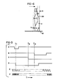
- Figure 6 illustrates a leading edge 28 of a container 11 being horizontally transported by conveyor 12.
- the point Q represents the location of trigger cell 17, and the point P represents the location of one of the registration photodetectors 18.
- container 11 has reached a recognition position (e.g. one of the positions indicated by dotted lines 26 and 27 of Figure 2) at which leading edge 28 is passing in front of point P.
- Container 11 has therefore travelled a total distance g since the instant when the trigger cell was crossed by leading edge 28.
- the distance x is the horizontal distance between that point on leading edge 28 which is at the height of the trigger cell and another point on leading edge 28 which has the same height as the point P. This distance is a unique characteristic of container 11 and is used for container recognition.
- the system establishes the distance x by measuring the distance g and subtracting the distance y.
- Y is merely the known horizontal distance between points Q and P, while the distance g is determined by counting conveyor clock pulses.
- FIG. 3 illustrates the time sequence of the various signals associated with the container recognition sequence.
- the signal A represents the signal generated on Line 20a by height detecting photodetector 19a.
- Signals B and C represent signals on lines 21a and 21b which are generated respectively by registration photodetectors 18a and 18b.
- Signal D is the signal on line 22 from trigger photodetector 17.
- Signal E is the conveyor clock signal on line 24, and line F is a crystal controlled system clock signal, which has a frequency considerably higher than the nominal frequency of occurrence of conveyor clock pulses.
- trigger signal D undergoes a light-to-dark transition due to the passage of the container leading edge across the point Q.
- signal A is indicating a dark condition for height detecting photodector 19a, which operates as hereinafter described for enabling container recognition by a predetermined set of recognition circuits.
- the system begins counting conveyor clock pulses (Signal E) and continues counting until time t 2 , when signal C indicates observation of a light-to-dark transition by registration photodetector 18b. That count is compared against a predetermined range of counts in order to determine whether or not a recognition should be generated.
- there is another counter which continues counting past time t 2 until time t 31 when signal B indicates detection of light-to-dark transition by registration photodetector 18a.
- the distance g is known from the relation: where % represents the amount of conveyor movement during the period of one conveyor clock pulse.
- the system is so designed as to generate a container recognition only under the condition: where x min is a minimum permissible value of x corresponding to a lower limit count N mi n and x is a maximum permissible value min max of x corresponding to an upper limit count N
- the counts max. N and N are established on the basis of experience with min max different bottle types, and recognition is indicated when the system makes a count N fulfilling the conditions:
- the system has a counter which overflows at a count of 2 8 and which is preset with the number N where N P is defined by the relationship: Due to this preset, the actual count within the counter is N + N .
- the counter adds a new count for each new conveyor clock pulse. This counting continues until either terminated by a leading edge pulse from one of the registration photodetectors or until a 2 8 overflow count is reached. If the overflow condition is reached then the system knows that: and therefore, consequently a first type of out-of-range signal is generated.
- the counter is controlled to count rapidly downward until the comparator recognizes the condition:
- Such a successful downward count is an indication of a value of x within the predetermined range. The system therefore generates a recognition signal upon completion of such a downward count.
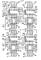
- FIG. 5 is a generalized system block diagram, while Figs. 4a through 4b present a schematic diagram of a recognition circuit. Figs. 4a through 4e and 5 include schematic representations of a number of standard integrated circuits. Table I identifies the various circuit types which are so illustrated.
- the recognition circuit illustrated in Figs. 4a through 4c is one of a number of recognition circuits, which may be employed for recognizing different containers.
- the block diagram of Fig. 5 includes five such recognition circuits 30.
- Each recognition circuit 30 is connected for reception of signals from two of the lines 21. As described above, lines 21 are connected to registration photodetectors 18.
- Recognition circuits 30 are also connected to line 22 for reception of a trigger signal and to line 24 for reception of conveyor clock pulse.
- Each recognition circuit 30 is operative for counting conveyor clock pulses which occur on line 24 subsequent to the appearance of a signal on line 22.
- Each recognition circuit has a pair of counting chains for performing two simultaneous counts. These two counts are terminated by leading edge transition signals appearing on the two lines 21 to which the recognition circuit is connected. It should be understood that such dual counting is a mere matter of convenience and that a recognition circuit 30 requires connection to only one of the lines 21.
- a priority encoder 150 and a decoder 151 for selecting recognition circuits in accordance with signals appearing on lines 20.
- Fig. 5 illustrates 8 lines 20, while 14 such lines are illustrated in Fig. 2. The remaining 6 lines are connected to an additional priority encoder and decoder arrangement (not illustrated).
- Priority encoder 150 has an enabling input line 152 and an enabling output line 153. As illustrated in Fig. 5, priority encoder 150 is connected to the group of lines 20 which carries signals from the 8 highest level height detecting photodetectors 19. Thus line 153 carries an enabling output signal from priority encoder 150 to the enabling input terminal of the other priority encoder.
- the illustrated priority encoder 150 is enabled by connecting line 152 to a constant voltage source.
- container 11 blocks the view of 11 height detecting photodetectors, the highest one of which is indicated at 19a.
- Photodetector 19a is positioned so as to be obscured by the upper portion of container 11 at the instant when the leading edge of the container passes a trigger photodetector 17. At that time photodetector 19a is darkened and has a dark signal output. In general the height detecting photo- detectors below photodetector 19a also are darkened at that time, but some of them may be viewing light spots. As a rule glass containers do not have light spots at the top, so it may be assumed that a container having the configuration of container 11 will always darken photodetector 19a at the time of trigger signal generation.
- photodetector 19a is the highest darkened light detecting photodetector at that time, it is known that container 11 has a height at least as high as photodetector 19a and less than the height of the next higher photodetector 19b. This provides a criterion for selectively activating a relatively small group of recognition circuits 30.
- Priority encoder 150 has three output lines 154, which carry a digital code indicating the highest one of the lines 20 which carries a dark indicating signal. Decoder 151 decodes the signal appearing on lines 154 and provides an output enabling signal on one of eight output lines 155. In the special case where line 20a happens to be the highest dark indicating line, then line 155a may be the activated output line from decoder 151. As illustrated in Fig. 5 line 155a may enable two recognition circuits 30a and 30b.
- Fig. 2 illustrates a container lla in dotted lines to indicate the geometry of a height classification problem for a somewhat larger container than that which was described above.
- FIG. 4a through 4c These figures collectively define a recognition circuit of 30, and common reference numerals are applied to all lines which are-commonly connected. Table II lists some of the signals appearing on various lines illustrated in the figures.
- the recognition circuit is enabled by an enabling signal on line 155.
- This signal is applied to the D terminal of a flip-flop 100, which enables the flip-flop to be set by application of a trigger signal to line 22.
- Setting of flip-flop 100 then causes the previously described preset count N count to be set into the counter chains.
- the two counter chains are separately conditioned by generation of container recognition signals, and the following discussion describes the operation of one of the chains in detail.
- the chain which will be described comprises a first counter 102 which is connected in cascade fashion with a second counter 103.
- the two counters may be thought of as being a single counter, which functions in the general manner previously described.
- the preset count N is set into counters 102 and 103 by making appropriate connections within a pair of resistor networks 134 and 135.
- the comparison of the count within the counters against a comparison count N is performed by a pair of cascaded comparators 107 and 108.
- the comparison count is set into comparators 107 and 108 by appropriate connections within a pair of resistor networks 134 and 135.
- flip-flop 109 When a container leading edge signal appears on line 21a, flip-flop 109 is reset, thereby causing downward counting by counters 102 and 103, disabling of AND gate 162, enabling of AND gate 164, and enabling of AND gates 167 and 168.
- AND gate 168 When AND gate 168 is enabled, the system is conditioned to respond to a lower limit out-of-range signal on line 169. Such an out-of-range signal will be present when comparators 107 and 108 detect a count lower than N , as above described. This condition produces a reset signal for flip-flop 131 in like manner as the upper limit out-of-range signal on line 106.
- comparators 107 and 108 do not detect a lower limit out-of-range condition, then counters 102 and 103 begin rapid downward counting of system clock pulses appearing on lines 914 and gated through AND gate 164. Downward counting proceeds until comparators 107 and 108 detect a count equal to N . When this condition is sensed, an output appears on line 110 for gating through AND gate 167 and setting of flip-flop 111. A resulting HI signal on line 170 indicates that the system has recognized the container.
- the system preferably bases container recognition upon successful generation of two independent recognition signals.
- the second counter chain comprising counters 104 and 105 is operated to produce a similar but independent recognition signal on line 171.
- the second counter chain has its own resistor networks 136 and 137 and a pair of comparators 126 and 127.
- Comparators 126 and 127 have resistor networks 138 and 139 for indication of a preset count N appropriate for evaluation of a leading edge transition signal appearing on line 21b.
- Resistor networks 136 and 137 indicate the corresponding appropriate preset count N .
- Triggering of monostable 118 also produces a LO signal on line 919, which resets both counting chains.
- Line 919 is interconnected with similar lines on other recognition circuits, so that generation of a container recognition signal by any recognition circuit resets the counting chains in all recognition circuits.
- Resetting of flip-flop 100 is accomplished by an output signal from OR gate 122, after the container has cleared the line of registration photodetectors. It has been found that the bottom photodetector has a reliably dark indication while the container is preset. A dark-to-light transition from this photodetector appears on line 910 for application to the reset terminal of flip-flop 100.
- Flip-flop 100 likewise is reset by signal from the carton recognition circuitry on line 911 or a master clear signal on line 912.
Landscapes
- Physics & Mathematics (AREA)
- General Physics & Mathematics (AREA)
- Length Measuring Devices By Optical Means (AREA)
Applications Claiming Priority (2)
| Application Number | Priority Date | Filing Date | Title |
|---|---|---|---|
| US42468 | 1979-05-25 | ||
| US06/042,468 US4259571A (en) | 1979-05-25 | 1979-05-25 | Apparatus and method for container recognition |
Publications (1)
| Publication Number | Publication Date |
|---|---|
| EP0020108A1 true EP0020108A1 (de) | 1980-12-10 |
Family
ID=21922097
Family Applications (1)
| Application Number | Title | Priority Date | Filing Date |
|---|---|---|---|
| EP80301717A Withdrawn EP0020108A1 (de) | 1979-05-25 | 1980-05-23 | Apparat und Verfahren zur Erkennung von Behältern |
Country Status (2)
| Country | Link |
|---|---|
| US (1) | US4259571A (de) |
| EP (1) | EP0020108A1 (de) |
Cited By (3)
| Publication number | Priority date | Publication date | Assignee | Title |
|---|---|---|---|---|
| WO1986006661A1 (en) * | 1985-05-14 | 1986-11-20 | Regionala Stiftelsen I Värmland Med Firma Erress | Apparatus for sorting cutlery |
| WO1992017287A3 (en) * | 1991-03-29 | 1993-02-18 | Csx Transportation Inc | Device to uniquely recognize travelling containers |
| WO1993009885A1 (en) * | 1991-11-11 | 1993-05-27 | Elektroindustrier As | Device for recording dimensions and shape of objects |
Families Citing this family (20)
| Publication number | Priority date | Publication date | Assignee | Title |
|---|---|---|---|---|
| GB2067326B (en) * | 1980-01-09 | 1983-03-09 | British United Shoe Machinery | Workpiece identification apparatus |
| DE3114285C2 (de) * | 1981-04-09 | 1983-05-19 | Fa. Hermann Heye, 3063 Obernkirchen | Prüfvorrichtung zur Feststellung von Mündungsfehlern von Glasgegenständen |
| US4354865A (en) * | 1981-05-01 | 1982-10-19 | Brockway Glass Company, Inc. | Automatic glass ware forming machine with automatic down and/or stuck bottle rejection |
| US4421542A (en) * | 1981-05-01 | 1983-12-20 | Brockway Glass Company, Inc. | Automatic glassware forming machine with automatic down and/or stuck ware rejection |
| US4494656A (en) * | 1983-04-01 | 1985-01-22 | Powers Manufacturing, Inc. | Down and stuck ware inspection method and apparatus |
| JPS6049787A (ja) * | 1983-08-31 | 1985-03-19 | 株式会社東京自働機械製作所 | 巻タバコ束の検査装置 |
| US4691231A (en) * | 1985-10-01 | 1987-09-01 | Vistech Corporation | Bottle inspection system |
| JP2524374B2 (ja) * | 1986-06-12 | 1996-08-14 | スカン コイン アクティエボラーグ | コイン仕分機 |
| US4912337A (en) * | 1988-06-03 | 1990-03-27 | Honeywell Inc. | Position responsive apparatus |
| DE4023149A1 (de) * | 1990-07-20 | 1992-01-23 | Kodak Ag | Vorrichtung zum abtasten von behaeltern mit einer fluessigkeit |
| WO1995007770A1 (en) * | 1993-09-17 | 1995-03-23 | Thermedics Detection Inc. | Device for sorting and distributing of packaging units |
| US5532605A (en) * | 1994-10-27 | 1996-07-02 | Agr International, Inc. | Container inspection apparatus having diameter measuring means and associated method |
| US5502755A (en) * | 1995-04-10 | 1996-03-26 | Trion Industries, Inc. | High speed, high accuracy parts counting system |
| JP3032159B2 (ja) * | 1996-09-24 | 2000-04-10 | 株式会社日立製作所 | 分析システム |
| US6365906B1 (en) * | 1999-07-22 | 2002-04-02 | Ambec, Incorporated | Method and apparatus for detecting and ejecting misaligned containers |
| FR2905880A1 (fr) * | 2006-09-14 | 2008-03-21 | Briane Environnement Soc Par A | Procede et dispositif de triage de contenants a des fins de recyclage |
| US8077051B2 (en) * | 2008-01-18 | 2011-12-13 | Sensors Incorporated | Fault detection system with redundant product teach verification |
| US9147326B2 (en) | 2008-01-18 | 2015-09-29 | Sensors Incorporated | Encoder based speed compensated reject system and method |
| US10198653B2 (en) | 2017-04-26 | 2019-02-05 | Sensors Incorporated | System and method for performing production line product identification |
| US11908122B2 (en) | 2017-04-26 | 2024-02-20 | Sensors Incorporated | System and method for performing production line product identification |
Citations (5)
| Publication number | Priority date | Publication date | Assignee | Title |
|---|---|---|---|---|
| US3529169A (en) * | 1967-12-06 | 1970-09-15 | Fmc Corp | Photoelectric apparatus for detecting shape of bottles |
| US3837486A (en) * | 1973-07-09 | 1974-09-24 | Emhart Corp | Article inspection system |
| US4120403A (en) * | 1976-06-28 | 1978-10-17 | George E. Lauer | Photoelectric apparatus for sorting variegated articles according to size |
| FR2400969A1 (fr) * | 1977-08-24 | 1979-03-23 | Hugin Kassaregister Ab | Appareil d'identification et d'enregistrement de bouteilles |
| EP0007248A2 (de) * | 1978-07-17 | 1980-01-23 | The Mead Corporation | Vorrichtung und Verfahren zur Klassifizierung von leeren Getränkebehältern |
Family Cites Families (2)
| Publication number | Priority date | Publication date | Assignee | Title |
|---|---|---|---|---|
| GB1048585A (en) * | 1962-07-20 | 1966-11-16 | North Atlantic Res Products Lt | Apparatus for the automatic dimensional inspection of an object |
| US3955179A (en) * | 1971-12-14 | 1976-05-04 | Tore Planke | Apparatus for automatic pattern recognition and registration of empty bottles |
-
1979
- 1979-05-25 US US06/042,468 patent/US4259571A/en not_active Expired - Lifetime
-
1980
- 1980-05-23 EP EP80301717A patent/EP0020108A1/de not_active Withdrawn
Patent Citations (5)
| Publication number | Priority date | Publication date | Assignee | Title |
|---|---|---|---|---|
| US3529169A (en) * | 1967-12-06 | 1970-09-15 | Fmc Corp | Photoelectric apparatus for detecting shape of bottles |
| US3837486A (en) * | 1973-07-09 | 1974-09-24 | Emhart Corp | Article inspection system |
| US4120403A (en) * | 1976-06-28 | 1978-10-17 | George E. Lauer | Photoelectric apparatus for sorting variegated articles according to size |
| FR2400969A1 (fr) * | 1977-08-24 | 1979-03-23 | Hugin Kassaregister Ab | Appareil d'identification et d'enregistrement de bouteilles |
| EP0007248A2 (de) * | 1978-07-17 | 1980-01-23 | The Mead Corporation | Vorrichtung und Verfahren zur Klassifizierung von leeren Getränkebehältern |
Cited By (4)
| Publication number | Priority date | Publication date | Assignee | Title |
|---|---|---|---|---|
| WO1986006661A1 (en) * | 1985-05-14 | 1986-11-20 | Regionala Stiftelsen I Värmland Med Firma Erress | Apparatus for sorting cutlery |
| US4750621A (en) * | 1985-05-14 | 1988-06-14 | Regionala Stiftenlsen i Varmland med firma ERRESS | Apparatus for sorting cutlery |
| WO1992017287A3 (en) * | 1991-03-29 | 1993-02-18 | Csx Transportation Inc | Device to uniquely recognize travelling containers |
| WO1993009885A1 (en) * | 1991-11-11 | 1993-05-27 | Elektroindustrier As | Device for recording dimensions and shape of objects |
Also Published As
| Publication number | Publication date |
|---|---|
| US4259571A (en) | 1981-03-31 |
Similar Documents
| Publication | Publication Date | Title |
|---|---|---|
| US4259571A (en) | Apparatus and method for container recognition | |
| US4020357A (en) | Signal processing for print scanners | |
| US4494656A (en) | Down and stuck ware inspection method and apparatus | |
| US4076979A (en) | Bottle color identification apparatus | |
| CA1145049A (en) | Bar code reader system | |
| US4158835A (en) | Arrangement for detecting a window area of a window-having mail item | |
| US4446481A (en) | Automatic product inspection system | |
| US4998626A (en) | Mail processing machine | |
| US4079416A (en) | Electronic image analyzing method and apparatus | |
| US4378494A (en) | Apparatus and method for detecting defects in glass bottles using event proximity | |
| US4459487A (en) | Method and apparatus for identifying objects such as bottles by shape | |
| US3886356A (en) | Optical inspection apparatus | |
| US4166949A (en) | Apparatus for identifying and registering bottles | |
| GB1585919A (en) | Bottle inspection apparatus | |
| CA1144652A (en) | Method and apparatus for the classification of piece goods which are in a state of motion | |
| GB2196767A (en) | Identification of a molded container with its mold of origin | |
| GB2094530A (en) | Apparatus and method for controlling the inspection of finished products | |
| US5149977A (en) | Document reader apparatus | |
| IE54009B1 (en) | Process and device for detecting foreign bodies in a liquid | |
| US4764681A (en) | Method of and apparatus for electrooptical inspection of articles | |
| US5259513A (en) | Method and a device for sorting returnable bottles, cans and other returnable packages | |
| GB2248930A (en) | Defect inspection method and apparatus using image processing with pattern detection and identification steps | |
| US3643065A (en) | Code recognition apparatus and method | |
| US3894217A (en) | Device for discriminating color coded articles | |
| CA1139885A (en) | Apparatus and method for container recognition |
Legal Events
| Date | Code | Title | Description |
|---|---|---|---|
| PUAI | Public reference made under article 153(3) epc to a published international application that has entered the european phase |
Free format text: ORIGINAL CODE: 0009012 |
|
| AK | Designated contracting states |
Designated state(s): AT BE CH DE FR GB IT LI LU NL SE |
|
| 17P | Request for examination filed |
Effective date: 19810605 |
|
| ITF | It: translation for a ep patent filed | ||
| STAA | Information on the status of an ep patent application or granted ep patent |
Free format text: STATUS: THE APPLICATION IS DEEMED TO BE WITHDRAWN |
|
| 18D | Application deemed to be withdrawn |
Effective date: 19840113 |
|
| RIN1 | Information on inventor provided before grant (corrected) |
Inventor name: DUBBERLY, GREGORY T. |