EP0020199B1 - System zur Steuerung des Wechselns der gelesenen Seite für den optischen Leseapparat eines Informationsträgers - Google Patents
System zur Steuerung des Wechselns der gelesenen Seite für den optischen Leseapparat eines Informationsträgers Download PDFInfo
- Publication number
- EP0020199B1 EP0020199B1 EP80400552A EP80400552A EP0020199B1 EP 0020199 B1 EP0020199 B1 EP 0020199B1 EP 80400552 A EP80400552 A EP 80400552A EP 80400552 A EP80400552 A EP 80400552A EP 0020199 B1 EP0020199 B1 EP 0020199B1
- Authority
- EP
- European Patent Office
- Prior art keywords
- signal
- face
- control
- output
- logic
- Prior art date
- Legal status (The legal status is an assumption and is not a legal conclusion. Google has not performed a legal analysis and makes no representation as to the accuracy of the status listed.)
- Expired
Links
- 230000003287 optical effect Effects 0.000 title claims description 19
- 230000008859 change Effects 0.000 claims description 24
- 230000007704 transition Effects 0.000 claims description 14
- 238000001514 detection method Methods 0.000 claims description 4
- 238000004519 manufacturing process Methods 0.000 claims description 3
- 230000007423 decrease Effects 0.000 claims description 2
- 230000001360 synchronised effect Effects 0.000 claims 2
- 238000012806 monitoring device Methods 0.000 claims 1
- 238000000034 method Methods 0.000 description 15
- 230000008569 process Effects 0.000 description 9
- 230000001133 acceleration Effects 0.000 description 6
- 238000005530 etching Methods 0.000 description 5
- 238000010586 diagram Methods 0.000 description 4
- 230000000694 effects Effects 0.000 description 4
- 230000007246 mechanism Effects 0.000 description 4
- 230000004069 differentiation Effects 0.000 description 2
- 238000006073 displacement reaction Methods 0.000 description 2
- 230000003071 parasitic effect Effects 0.000 description 2
- 241001080024 Telles Species 0.000 description 1
- 230000004075 alteration Effects 0.000 description 1
- 239000003990 capacitor Substances 0.000 description 1
- 230000000295 complement effect Effects 0.000 description 1
- 230000003247 decreasing effect Effects 0.000 description 1
- 230000008034 disappearance Effects 0.000 description 1
- 235000021183 entrée Nutrition 0.000 description 1
- 239000012634 fragment Substances 0.000 description 1
- 230000005484 gravity Effects 0.000 description 1
- 230000010354 integration Effects 0.000 description 1
- 238000012423 maintenance Methods 0.000 description 1
- 239000000463 material Substances 0.000 description 1
- 230000004048 modification Effects 0.000 description 1
- 238000012986 modification Methods 0.000 description 1
- 210000000056 organ Anatomy 0.000 description 1
- 238000011084 recovery Methods 0.000 description 1
- 238000004904 shortening Methods 0.000 description 1
- 238000013518 transcription Methods 0.000 description 1
- 230000035897 transcription Effects 0.000 description 1
- 230000001052 transient effect Effects 0.000 description 1
Images



Classifications
-
- G—PHYSICS
- G11—INFORMATION STORAGE
- G11B—INFORMATION STORAGE BASED ON RELATIVE MOVEMENT BETWEEN RECORD CARRIER AND TRANSDUCER
- G11B19/00—Driving, starting, stopping record carriers not specifically of filamentary or web form, or of supports therefor; Control thereof; Control of operating function ; Driving both disc and head
- G11B19/02—Control of operating function, e.g. switching from recording to reproducing
-
- G—PHYSICS
- G11—INFORMATION STORAGE
- G11B—INFORMATION STORAGE BASED ON RELATIVE MOVEMENT BETWEEN RECORD CARRIER AND TRANSDUCER
- G11B7/00—Recording or reproducing by optical means, e.g. recording using a thermal beam of optical radiation by modifying optical properties or the physical structure, reproducing using an optical beam at lower power by sensing optical properties; Record carriers therefor
- G11B7/08—Disposition or mounting of heads or light sources relatively to record carriers
- G11B7/085—Disposition or mounting of heads or light sources relatively to record carriers with provision for moving the light beam into, or out of, its operative position or across tracks, otherwise than during the transducing operation, e.g. for adjustment or preliminary positioning or track change or selection
Definitions
- the invention relates to a control system for changing the read face for an optical reader of an information medium, and in particular of a video disc.
- the correct focusing of the light brush is most often obtained by means of a focusing servo device comprising a feedback loop keeping the distance between the optical device and the engraved surface of the disc constant.
- the attachment and the maintenance of the servo device are obtained by the detection of the electrical signal corresponding to the engraving.
- the simplest way to obtain the passage of the focusing, and therefore of the reading, from one face to the other consists in opening the loop of the focusing servo control device for a preset time T and operating at focusing device a translational movement corresponding to the movement from one face of the disc to the other face.
- This translational movement is obtained by applying to the focusing device a current pulse correctly calibrated in duration and in amplitude so that the device moves exactly the thickness of the disc during the time T. At this instant, it suffices to close the loop of the focusing servo device so that it hooks onto the opposite face. This very simple process does not give satisfactory results in practice.
- the translational movement from one face to the other comprises two phases: during the first phase the focusing device is animated by a uniformly accelerated movement during the duration of the current pulse ; during the second phase, the device is animated by a ballistic movement depending on the speed acquired during the first phase.
- this speed as well as the path traveled during this first phase, depend not only on the acceleration that is applied to the focusing device by means of the calibrated pulse but also on the initial speed of movement of this device at the instant of application of the current pulse.
- the friction of the mechanical parts of the focusing device can vary as a function of temperature, humidity or other parameters that are difficult to control.
- Figure 1 illustrates the mechanism of the optical reading of a transparent videodisc engraved on its two faces.
- the focusing device as well as the recording method by burning microcuvettes on a video disc are well known to those skilled in the art. This device and this method are outside the scope of the invention. It is however useful to recall its general principles.
- a light brush produced by a laser (not shown in FIG. 1) is focused on one of the faces, for example the face f 2 , of a video disc using an optical system symbolized by the lens L in position II, the optical center of this lens L (II) is located on an axis Y 2 , parallel to the axis Y of the reference triede XYZ drawn in FIG. 1.
- This videodisc comprises concentric tracks comprising microcuvettes 3 on the side f 1 and 2 on the side f 2 . These microcuvettes represent coded information. This information is read by focusing the beam 6 on these microcuvettes. In FIG. 1, this focusing is illustrated by the spot A. The light rays are then diffracted by the microcuvettes and detected by photoelectric cells 4 and 5, the outputs S and S 2 of which are connected to the inputs of a differential amplifier not shown. The diffraction spot in the plane of cells 4 and 5 is illustrated in FIG. 1 by the reference A 1 . The beam, focused on the face f2, forms a spot A 2 on the face f 1 whose dimensions are much larger than the dimensions of the microcuvettes 3 etched on this face. The light rays focused on the face f 2 are therefore not disturbed by the microcuvettes 3 when crossing this face. Under these conditions, the etching of the face f 1 has no influence on the electrical signal delivered by the cells placed under the disc 4 and 5.
- the photoelectric cells 4 and 5 will therefore detect a high frequency signal modulated respectively by the microcuvettes 3 or 2.
- This signal is used on the one hand for the actual reading of the information and, on the other hand, to open or close the feedback loop of the servo device. To do this, high frequency signals are detected. This process is well known to those skilled in the art and will not be described further.
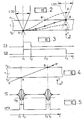
- FIGS 2 and 3 illustrate the process for changing the face read in the known art, described above.
- the focusing device is slaved to the side f 2 of the video disc 1.
- This signal has a duration T equal to t, t 3 .
- a calibrated pulse IS is applied to the organs controlling the movement of the focusing device for a time equal to the duration t 1 t 2 .
- This pulse is intended to impart to the focusing device a translational movement towards the face f 1 , which it is assumed to reach at point B after a time T equal to t 1 t 3 .
- t 3 it suffices to close the feedback loop of the focusing servo device so that it hooks onto the new read face, that is to say the face f 1 .
- the focusing device symbolized by the optic L (I) is animated by a uniformly accelerated movement towards position II.
- the speed acquired during this first phase depends not only on the acceleration that is applied to the focusing device by means of the calibrated pulse but also on the initial speed of movement of this device at time t 1 .
- This initial speed is added algebraically to the acquired speed. It follows that under certain conditions the focusing device moves more or less quickly than the speed of movement corresponding to the average trajectory AB. For a higher speed of displacement, one obtains for example the trajectory AB 'D during time T and for a lower speed of displacement, one obtains the trajectory A C. It follows that in the first case, the crossing of the face f 1 is done at point B ', that is to say at time t 3 whereas in the second case, at time t 3 , point A is at C and has not yet crossed face f 1 . Points D and C are too far from face f, to obtain rapid and correct attachment of the focusing servo device to side f 1 of the video disc when the feedback loop of the servo device is closed again .
- Detection includes a recovery operation and an integration operation.
- the "HFD" pulse has a logic level "1 during the intervals t 1 t 2 and t 3 t 4.
- the durations of these intervals are precisely determined by a logic with threshold D s .
- the threshold D s being chosen high enough to eliminating any parasitic noise signals and unambiguously discriminating the appearance of the high frequency signal.
- the loop of the focusing servo-control device is opened, by means of the signal OB, at the same time as a short command pulse is applied to it.
- IS face jump Under the effect of this pulse, the focal point leaves the face f 2 of the videodisc at point A to go towards the face f 1 along the path AB, which has the effect of extinguishing the high frequency HF signal from reading of the face f 2 , causing the tilting of the detected signal HFD, when the high frequency signal decreases below the predetermined threshold D s .
- the focal point will cross the face f 1 .
- the high frequency HF signal will start to grow again for reach the threshold D S. It follows that the detected signal HFD switches again, this transition causing in turn, the switching of the signal OB and the closing of the feedback loop of the focusing servo device, causing it to catch on. on side f, of the disc. In synchronism with the closing of the loop, a braking pulse is sent to the focusing device to avoid the ballistic shift of the point B, this pulse having a polarity opposite to the acceleration pulse.
- the process for passing from face f 1 to face f 2 comprises the same steps, it is only necessary to reverse the respective directions of the acceleration and braking pulses. These pulses can be generated in a very simple manner, by differentiating the signal for opening / closing loop OB or its complement.
- the servo device works absolutely safely when the disc does not have any engraving on one of its faces, this non-engraved face delivering no signal, it is not possible that the servo - mechanism focus can hang on to it. It is not the same if the two sides of the disc carry engraved information, in fact each of the faces being able to deliver a modulated electrical signal, the control device can be hooked either on one or the other. 'other without it being possible to differentiate them, especially during the initial hanging. In addition, under the influence of transient parasitic signals, an unwanted change of face can occur. In this case, if for example the previously read face was the face f 1 , the control device will remain attached to the face f 2 and the information read will be the information engraved on. the side f 2 .
- any process and device can be used to recognize the read face.
- This record can contain 40 bits.
- a bit is added to the bit stream representing the sound channel.
- the bits of the sound channel carry numbers ranging from 1 to 40.
- An additional bit identifies the read face. This bit is permanently carried to the logical level "0" for one of the faces and to the logical level "1" for the other face. This bit as well as the sound bits are recorded during the line scan return interval.
- this additional bit representing the read face is transmitted to the read face change control system.
- FIG. 8 describes a preferred embodiment of the control system for changing the face read according to the invention.
- Reference 1 represents the usual circuits of a video disc player as well as the associated clock and synchronization circuits, providing in particular the clock signals H 3 at the line scanning frequency necessary for the device for controlling the face. read, represented in FIG. 8 by the reference DSU.
- These circuits also provide the additional bit representing the face read on the connection 42 as well as the high frequency HF signal coming from the reading of the information engraved on one or the other face and a direct voltage V representing the logic level "1" according to the standard of integrated circuits used. This last voltage is in the case of a standard called "TTL", of 5 volts.
- the face change control system essentially comprises three circuits.
- a first control circuit CD 1 producing a binary signal Cd of "read-side change command”
- a second control circuit CD 2 producing the loop open / close signal OB
- a generator GE producing a control pulse IS side jump
- the circuit CD can be constituted simply by a switch to. two directions, alternately connecting the output Cd to a logic value "1" (V) or a logic value "0" (symbolized by the circuit earth).
- the additional bit identifying the read face arrives on an input of the "EXCLUSIVE" door 8, this door receives on its other input is the control signal Cd.
- this gate 8 Depending on the position of the switch for choosing the face of the control circuit CD 1 , this gate 8 lets the additional bit pass without modification, this is the case for example of the face f, for which this bit is by convention always at “0" or, and this is the case of face f 2 , for which the additional bit is always at "1", gate 8 reverses the bit.
- the output of the "EXCLUSIVE" gate 80 is transmitted to the serial input of a shift register 3 with eight parallel outputs (30-1 / 30-8). When one is correctly positioned on the desired side by CD 1 , the entry of the shift register 3 receives only "0" (apart from possibly some erroneous bits due to alterations occurring during the transcription process).
- the CD switch If, being positioned on one of the sides of the disc, in stabilized reading mode, the CD switch is operated from one position to the other, which is the case on the timing diagram of FIG. 9 at the moment t o , the switching of this switch causes, via gate 8, a change of state of the consecutive additional bits arriving at input 80 of the shift register 3. It is then a succession of bits all at level "1" who enter this register. At the end of the eighth consecutive bit at level "1" entered in register 3, that is to say at the end of time t 7 , it has level 1 on all outputs 30-1 to 30-8, which causes the change of state from "1" to "0" of the SA output of door 4.
- This change of state triggers a monostable flip-flop 5, which by its reverse output Q 5 causes the flip-flop of a bistable flip-flop of type RS: 7 formed by the two "NAND” gates 71 and 72.
- the output Q of this flip-flop provides the signal for opening / closing of feedback loop OB.
- the high frequency HF signals originating from the reading of the etchings representing the recorded information are detected, that is to say rectified and integrated, by a circuit 2 providing a detected HFD signal, inverted by the inverter 100 and transmitted to the input R of the flip-flop 7.
- Circuit 2 also includes threshold logic intended to eliminate noise.
- the "EXCLUSIVE" gate 9 and the RC differentiation circuit are intended to deliver face jump and braking pulses of suitable polarity.
- the circuit can only deliver pulses making it possible to perform a jump from face f 2 towards face f 1 , and when CD 1 is positioned on face f 2 , the "OU-EXCLUSIVE" gate 9 becoming inverting, the pulses delivered only allow the passage from face f 1 to face f 2 .
- the bistable flip-flop 7 is controlled by the output Q 5 of the monostable flip-flop 3 on its input 5 and the HFD signal on its input R, Or, if the change to "0" of the output Q 3 of the monostable flip-flop 5 causes good the passage to "1" of the output Q 7 of the flip-flop 7, this state remains fleeting as long as the input R has not passed to the state "1", which only intervenes when under the effect of the jump pulse IS, the focal point of the reading device is sufficiently distant from the engraving of the face that one wants to leave.
- the command on input S must therefore be maintained for a sufficiently long time (approximately 500 ms), this is the purpose of the monostable flip-flop 5.
- the monostable flip-flop 6 is intended for its part to prevent access to register 3 additional bits, necessarily erroneous, which arrive during the passage time from one face to the other and thus avoid the production of erroneous pulses SA.
- This monostable rocker 6 produces pulses of sufficient length to allow the various servomechanisms to stabilize on the new face after each jump (approximately 100 to 250 milliseconds).
- the reset input (RESET) of register 3 is connected to output Q 6 of the monostable flip-flop 6. Thus, it is not allowed to change the faces again before this time has elapsed.
- the face control device read DSU constantly checks that the focusing servo mechanism is correctly positioned on the face of the disc that has been selected. Indeed if this were not the case, the additional bits would arrive at state "1" on input 80 of the shift register 3, and at the end of the eighth consecutive bit in state "1" would automatically trigger the previously described process of face change. This is particularly useful for automatically positioning the reading device on the chosen side when changing discs.
- the differentiator circuit 200 can be constituted by a resistor with a typical value of 10 K ⁇ and a capacitor with a typical value of 10,000 pF.
Landscapes
- Optical Recording Or Reproduction (AREA)
- Moving Of The Head For Recording And Reproducing By Optical Means (AREA)
- Automatic Focus Adjustment (AREA)
Claims (7)
Applications Claiming Priority (2)
| Application Number | Priority Date | Filing Date | Title |
|---|---|---|---|
| FR7913981 | 1979-05-31 | ||
| FR7913981A FR2458126A1 (fr) | 1979-05-31 | 1979-05-31 | Systeme de commande de changement de face lue pour un lecteur optique de support d'information et lecteur optique comportant un tel systeme |
Publications (2)
| Publication Number | Publication Date |
|---|---|
| EP0020199A1 EP0020199A1 (de) | 1980-12-10 |
| EP0020199B1 true EP0020199B1 (de) | 1983-09-21 |
Family
ID=9226102
Family Applications (1)
| Application Number | Title | Priority Date | Filing Date |
|---|---|---|---|
| EP80400552A Expired EP0020199B1 (de) | 1979-05-31 | 1980-04-23 | System zur Steuerung des Wechselns der gelesenen Seite für den optischen Leseapparat eines Informationsträgers |
Country Status (6)
| Country | Link |
|---|---|
| US (1) | US4337532A (de) |
| EP (1) | EP0020199B1 (de) |
| JP (1) | JPS55160337A (de) |
| CA (1) | CA1143060A (de) |
| DE (1) | DE3064887D1 (de) |
| FR (1) | FR2458126A1 (de) |
Cited By (3)
| Publication number | Priority date | Publication date | Assignee | Title |
|---|---|---|---|---|
| FR2505536A1 (fr) * | 1981-05-11 | 1982-11-12 | Sony Corp | Appareil de lecture d'informations optiques notamment sur un disque |
| EP0111010A4 (de) * | 1982-06-04 | 1986-07-17 | Sony Corp | Wiedergabegerät mit optischer scheibe. |
| US5757744A (en) * | 1995-07-31 | 1998-05-26 | U.S. Philips Corporation | Optical scanning apparatus for a multi-layer record carrier, including a focus control circuit |
Families Citing this family (16)
| Publication number | Priority date | Publication date | Assignee | Title |
|---|---|---|---|---|
| JPS57120237A (en) | 1981-01-14 | 1982-07-27 | Sony Corp | Optical reproducing device |
| JPS5877035A (ja) * | 1981-10-08 | 1983-05-10 | Mitsubishi Electric Corp | 自動焦点引込み装置 |
| US4446546A (en) * | 1981-12-31 | 1984-05-01 | Magnetic Peripherals Inc. | Focus initialization system for optical recording |
| US4497049A (en) * | 1982-02-25 | 1985-01-29 | Staar S. A. | System for detecting the operative face of a disc carrying data on one face only |
| JPS58155527A (ja) * | 1982-03-10 | 1983-09-16 | Hitachi Ltd | 光デイスクプレ−ヤのフオ−カス引き込み回路 |
| JPS6355735A (ja) * | 1986-08-26 | 1988-03-10 | Nippon Telegr & Teleph Corp <Ntt> | 光記録装置及び光再生装置 |
| US4980880A (en) * | 1989-11-06 | 1990-12-25 | Laser Magnetic Storage International Company | Method and apparatus for simultaneously reading both sides of an optical storage disk |
| JPH0485729A (ja) * | 1990-07-27 | 1992-03-18 | Nec Corp | 光学的再生装置 |
| JPH04364229A (ja) * | 1990-11-01 | 1992-12-16 | Matsushita Electric Ind Co Ltd | 光方式記録再生方法および記録媒体、光方式記録再生装置 |
| NL9002841A (nl) * | 1990-12-21 | 1992-07-16 | Philips Nv | Werkwijze en inrichting voor het langs optische weg inschrijven, uitlezen, en wissen van een meervlaks registratiedrager, en registratiedrager geschikt voor deze werkwijze en inrichting. |
| US7286153B1 (en) | 1991-10-11 | 2007-10-23 | Hitachi, Ltd. | Three-dimensional recording and reproducing apparatus |
| JP3266627B2 (ja) * | 1991-10-11 | 2002-03-18 | 株式会社日立製作所 | 情報再生装置 |
| EP0787341B1 (de) * | 1995-06-01 | 2002-10-30 | Philips Electronics N.V. | Optische abtastvorrichtung eines mehrschichtigen aufzeichnungsträgers mit fokusregelungsschaltung |
| CN1075222C (zh) | 1995-07-27 | 2001-11-21 | 松下电器产业株式会社 | 光盘装置 |
| JP3546549B2 (ja) * | 1995-08-04 | 2004-07-28 | ソニー株式会社 | 光学式ディスク駆動装置および方法 |
| US7522480B2 (en) | 2001-01-25 | 2009-04-21 | Dphi Acquisitions, Inc. | Digital tracking servo system with multi-track seek with an acceleration clamp |
Family Cites Families (6)
| Publication number | Priority date | Publication date | Assignee | Title |
|---|---|---|---|---|
| US3848095A (en) * | 1972-12-20 | 1974-11-12 | I O Metrics Corp | Three dimensional electro-optical retrieval system |
| US3946367A (en) * | 1972-12-20 | 1976-03-23 | Videonics Of Hawaii, Inc. | Three dimensional electro-optical retrieval system |
| NL182257C (nl) * | 1974-12-23 | 1988-02-01 | Philips Nv | Inrichting voor het uitlezen van een vlakke reflekterende registratiedrager waarop informatie is aangebracht in een optisch uitleesbare struktuur. |
| NL7509906A (nl) * | 1975-08-21 | 1977-02-23 | Philips Nv | Inrichting voor het uitlezen van een schijfvor- mige registratiedrager. |
| FR2330062A1 (fr) * | 1975-10-31 | 1977-05-27 | Thomson Brandt | Dispositif de recherche de focalisation et lecteur optique comportant un tel dispositif |
| JPS54124705A (en) * | 1978-03-20 | 1979-09-27 | Teac Corp | Optical reproducer |
-
1979
- 1979-05-31 FR FR7913981A patent/FR2458126A1/fr active Granted
-
1980
- 1980-04-23 EP EP80400552A patent/EP0020199B1/de not_active Expired
- 1980-04-23 DE DE8080400552T patent/DE3064887D1/de not_active Expired
- 1980-05-29 US US06/154,435 patent/US4337532A/en not_active Expired - Lifetime
- 1980-05-29 CA CA000352988A patent/CA1143060A/en not_active Expired
- 1980-05-30 JP JP7264180A patent/JPS55160337A/ja active Granted
Cited By (4)
| Publication number | Priority date | Publication date | Assignee | Title |
|---|---|---|---|---|
| FR2505536A1 (fr) * | 1981-05-11 | 1982-11-12 | Sony Corp | Appareil de lecture d'informations optiques notamment sur un disque |
| EP0111010A4 (de) * | 1982-06-04 | 1986-07-17 | Sony Corp | Wiedergabegerät mit optischer scheibe. |
| US5757744A (en) * | 1995-07-31 | 1998-05-26 | U.S. Philips Corporation | Optical scanning apparatus for a multi-layer record carrier, including a focus control circuit |
| US5793721A (en) * | 1995-07-31 | 1998-08-11 | U.S. Philips Corporation | Optical scanning apparatus for a multi-layer record carrier, including a focus control circuit |
Also Published As
| Publication number | Publication date |
|---|---|
| DE3064887D1 (en) | 1983-10-27 |
| EP0020199A1 (de) | 1980-12-10 |
| FR2458126B1 (de) | 1983-06-17 |
| FR2458126A1 (fr) | 1980-12-26 |
| CA1143060A (en) | 1983-03-15 |
| JPS6153771B2 (de) | 1986-11-19 |
| JPS55160337A (en) | 1980-12-13 |
| US4337532A (en) | 1982-06-29 |
Similar Documents
| Publication | Publication Date | Title |
|---|---|---|
| EP0020199B1 (de) | System zur Steuerung des Wechselns der gelesenen Seite für den optischen Leseapparat eines Informationsträgers | |
| EP0089263B1 (de) | Vorgeprägter beweglicher Informationsträger und optische Spurfolgeanordnung dafür | |
| EP0097092B1 (de) | Verfahren und optisches Gerät zum Fokussieren eines Lichtstrahlbündels auf eine Bezugsebene eines Informationenträgers | |
| EP0126682B1 (de) | Verfahren und Vorrichtung zur Festlegung der für Datenaufnahme auf eine optische Scheibe aufgebrachten optischen Leistung | |
| FR2569038A1 (fr) | Appareil d'enregistrement et de reproduction d'informations | |
| FR2534709A1 (fr) | Systeme de commande de l'entrainement d'un disque | |
| FR2473769A1 (fr) | Porteur d'information en forme de disque explorable par voie optique, et servant de milieu d'emmagasinage d'information, dispositif pour la fabrication d'un tel porteur d'information, dispositif pour l'enregistrement d'information dans un tel porteur d'information et dispositif pour la lecture de l'information d'un tel porteur | |
| EP0089264B1 (de) | Verfahren und Anordnung zur Regenerierung von Synchronisationssignalen in einem optischen Aufzeichnungs-Wiedergabegerät für Informationsträger | |
| FR2523349A1 (fr) | Procede et dispositif optique de generation de signaux d'asservissements de la position d'une tache d'exploration des pistes d'un support d'information | |
| EP0090690B1 (de) | Verfahren und Anordnung zur Regenerierung der Phase der Synchronisationssignale in einem optischen Aufzeichnungswiedergabegerät für Informationsträger | |
| FR2488031A1 (fr) | Appareil de reproduction d'un support d'enregistrement rotatif a recherche automatique de parties d'enregistrement a reproduire | |
| FR2508686A1 (fr) | Appareil pour la reproduction d'un signal d'information | |
| FR2524681A1 (fr) | Procede d'enregistrement d'un signal d'information numerique sur un support d'information muni d'une couche d'information sensible au rayonnement, dispositif pour la mise en oeuvre de ce procede et support d'information optique muni d'un signal que de ce genre | |
| FR2484118A1 (fr) | Dispositif pour rechercher une piste d'information desiree | |
| FR2490389A1 (fr) | Systeme de recherche a grande vitesse pour appareil de reproduction de supports d'enregistrement rotatifs | |
| EP0133067B1 (de) | Verfahren und Anordnung zur Regenerierung von wiedergegebenen, auf einer optischen Platte aufgezeichneten Datensignalen | |
| EP0072723B1 (de) | Optische Anordnung zur Spurhaltung mittels Stichprobenauswertung | |
| FR2558001A1 (fr) | Procede et appareil pour la recherche d'une piste sur un support optique d'information. | |
| EP0609398B1 (de) | Verfahren und anordnung zum aufzeichnen-wiedergeben von information auf einem beweglichen optischen oder magneto-optischen aufzeichnungsträger | |
| FR2512250A1 (fr) | Appareil de lecture de disque | |
| FR2484738A1 (fr) | Procede pour le codage de bits de donnees sur un porteur d'enregistrement, dispositif pour la mise en oeuvre du procede, porteur d'enregistrement pourvu d'une structure d'information, et dispositif pour decoder le signal lu sur le porteur d'enregistrement | |
| FR2514541A1 (fr) | Appareil pour reproduire un disque tel qu'un disque audio a signaux numeriques pcm | |
| FR2502877A1 (fr) | Appareil de lecture d'images fixes | |
| FR2516287A1 (fr) | Lecteur de disque | |
| FR2489996A1 (fr) | Circuit de detection de signaux periodiques dans un appareil reproducteur |
Legal Events
| Date | Code | Title | Description |
|---|---|---|---|
| PUAI | Public reference made under article 153(3) epc to a published international application that has entered the european phase |
Free format text: ORIGINAL CODE: 0009012 |
|
| AK | Designated contracting states |
Designated state(s): DE GB IT NL SE |
|
| 17P | Request for examination filed |
Effective date: 19801224 |
|
| ITF | It: translation for a ep patent filed | ||
| GRAA | (expected) grant |
Free format text: ORIGINAL CODE: 0009210 |
|
| AK | Designated contracting states |
Designated state(s): DE GB IT NL SE |
|
| REF | Corresponds to: |
Ref document number: 3064887 Country of ref document: DE Date of ref document: 19831027 |
|
| PLBE | No opposition filed within time limit |
Free format text: ORIGINAL CODE: 0009261 |
|
| STAA | Information on the status of an ep patent application or granted ep patent |
Free format text: STATUS: NO OPPOSITION FILED WITHIN TIME LIMIT |
|
| 26N | No opposition filed | ||
| ITTA | It: last paid annual fee | ||
| EAL | Se: european patent in force in sweden |
Ref document number: 80400552.8 |
|
| PGFP | Annual fee paid to national office [announced via postgrant information from national office to epo] |
Ref country code: NL Payment date: 19990315 Year of fee payment: 20 |
|
| PGFP | Annual fee paid to national office [announced via postgrant information from national office to epo] |
Ref country code: GB Payment date: 19990318 Year of fee payment: 20 |
|
| PGFP | Annual fee paid to national office [announced via postgrant information from national office to epo] |
Ref country code: DE Payment date: 19990320 Year of fee payment: 20 |
|
| PGFP | Annual fee paid to national office [announced via postgrant information from national office to epo] |
Ref country code: SE Payment date: 19990322 Year of fee payment: 20 |
|
| PG25 | Lapsed in a contracting state [announced via postgrant information from national office to epo] |
Ref country code: GB Free format text: LAPSE BECAUSE OF EXPIRATION OF PROTECTION Effective date: 20000422 |
|
| PG25 | Lapsed in a contracting state [announced via postgrant information from national office to epo] |
Ref country code: NL Free format text: LAPSE BECAUSE OF EXPIRATION OF PROTECTION Effective date: 20000423 |
|
| PG25 | Lapsed in a contracting state [announced via postgrant information from national office to epo] |
Ref country code: SE Free format text: THE PATENT HAS BEEN ANNULLED BY A DECISION OF A NATIONAL AUTHORITY Effective date: 20000429 |
|
| REG | Reference to a national code |
Ref country code: GB Ref legal event code: PE20 Effective date: 20000422 |
|
| EUG | Se: european patent has lapsed |
Ref document number: 80400552.8 |
|
| NLV7 | Nl: ceased due to reaching the maximum lifetime of a patent |
Effective date: 20000423 |