EP0020221A1 - Procédé de réglage de la température du verre dans une étenderie et étenderie pour la mise en oeuvre de ce procédé - Google Patents
Procédé de réglage de la température du verre dans une étenderie et étenderie pour la mise en oeuvre de ce procédé Download PDFInfo
- Publication number
- EP0020221A1 EP0020221A1 EP80400653A EP80400653A EP0020221A1 EP 0020221 A1 EP0020221 A1 EP 0020221A1 EP 80400653 A EP80400653 A EP 80400653A EP 80400653 A EP80400653 A EP 80400653A EP 0020221 A1 EP0020221 A1 EP 0020221A1
- Authority
- EP
- European Patent Office
- Prior art keywords
- glass
- temperature
- thermal
- air
- tubes
- Prior art date
- Legal status (The legal status is an assumption and is not a legal conclusion. Google has not performed a legal analysis and makes no representation as to the accuracy of the status listed.)
- Granted
Links
- 239000011521 glass Substances 0.000 title claims abstract description 30
- 238000000034 method Methods 0.000 title claims description 7
- 238000010438 heat treatment Methods 0.000 claims abstract description 13
- 238000001035 drying Methods 0.000 claims abstract description 10
- 238000001816 cooling Methods 0.000 claims description 11
- 238000011084 recovery Methods 0.000 description 2
- 238000000137 annealing Methods 0.000 description 1
- 230000033228 biological regulation Effects 0.000 description 1
- 239000004020 conductor Substances 0.000 description 1
- 238000010924 continuous production Methods 0.000 description 1
- 230000007423 decrease Effects 0.000 description 1
- 230000000694 effects Effects 0.000 description 1
- 238000005485 electric heating Methods 0.000 description 1
- 239000005357 flat glass Substances 0.000 description 1
- 230000003993 interaction Effects 0.000 description 1
- 239000003507 refrigerant Substances 0.000 description 1
Images

Classifications
-
- C—CHEMISTRY; METALLURGY
- C03—GLASS; MINERAL OR SLAG WOOL
- C03B—MANUFACTURE, SHAPING, OR SUPPLEMENTARY PROCESSES
- C03B25/00—Annealing glass products
- C03B25/04—Annealing glass products in a continuous way
- C03B25/06—Annealing glass products in a continuous way with horizontal displacement of the glass products
- C03B25/08—Annealing glass products in a continuous way with horizontal displacement of the glass products of glass sheets
-
- C—CHEMISTRY; METALLURGY
- C03—GLASS; MINERAL OR SLAG WOOL
- C03B—MANUFACTURE, SHAPING, OR SUPPLEMENTARY PROCESSES
- C03B29/00—Reheating glass products for softening or fusing their surfaces; Fire-polishing; Fusing of margins
- C03B29/04—Reheating glass products for softening or fusing their surfaces; Fire-polishing; Fusing of margins in a continuous way
- C03B29/06—Reheating glass products for softening or fusing their surfaces; Fire-polishing; Fusing of margins in a continuous way with horizontal displacement of the products
- C03B29/08—Glass sheets
Definitions
- Continuously produced flat glass passes through a thermally insulated tunnel, called a clothes line, which is provided with heating means as well as cooling means and in which the glass is cooled and annealed.
- the cooling means consist of a series of exchanger tubes which are placed inside the tunnel in two horizontal layers, on either side of the glass ribbon, being grouped in several batteries transverse and inside which air is circulated against the current, initially at room temperature.
- the heating means are electric, and formed by bare or shielded resistant wires placed between the exchanger tubes and the glass.
- This method of controlling the temperature of the glass has a number of serious drawbacks, in particular when it is a transparent glass ribbon and / or coated on one side with a highly reflective layer.
- glass is a poor conductor of heat and, when it cools, a notable temperature gradient appears between the surface of the glass ribbon and its central part. If the glass is still plastic, the stresses created by the temperature gradient produce a deformation of the glass ribbon. If the glass is sufficiently cooled to be perfectly elastic, this temperature gradient generates in the glass ribbon internal tensions which remain since the ribbon is no longer plastic.
- the cooling of the glass is uniform over the length of the drying rack, that is to say that the temperature of the glass decreases appreciably linearly.
- the cooling is not at all uniform; the glass cools down much more quickly at the exit from the considered area of the drying rack than at the entry of the latter, so that internal tensions are induced in the glass, in the central region of the annealing range .
- the glass cools more on its longitudinal edges than in its central part. If, in order to remedy this transverse temperature gradient, the heating means placed close to the longitudinal edges of the drying rack are put into service, these heating means radiate on the adjacent cooling means; this interaction makes it difficult to obtain a temperature which is optimal and uniform over the entire width of the glass ribbon.
- the present invention relates to a method for adjusting the temperature of the glass in a clothes rack which overcomes these drawbacks.
- the temperature is adjusted only with the aid of the exchanger tubes by admitting heated air at the inlet of this tube.
- the air passing through the tubes can circulate in open circuit or in closed circuit.
- the present invention also relates to a drying rack for the implementation of this method.
- the clothes line according to the invention is characterized in that it comprises means for heating the air introduced into the exchanger tubes.
- These heating means can be electric, with burners or be constituted by indirect heat exchangers.
- the drying rack may also include means for cooling the recycled air.
- These means can, for example, be constituted by a device for introducing cold air or by indirect refrigerant exchangers.
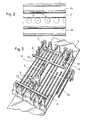
- the drying rack according to the invention comprises a heat-insulated tunnel 1 which comprises rollers 2 intended to support a glass ribbon 3 circulating in the direction of the arrow f l '
- each of these zones it comprises two horizontal plies of longitudinal exchanger tubes 4a and 4b placed one above the strip 3 and the other below. Each of these layers is divided transversely into batteries which are five in number in the embodiment shown.
- each of the batteries of tubes placed downstream of the zone in question, is connected to a flow control valve 5 and to heating means 6, for example with burners to which fresh air is admitted. at 7.
- the outlet of the tubes is connected by a manifold 8 to the suction of a fan 9 supplying a dis positive secondary heat recovery. The air thus flows against the current.
- a sensor 10 measures the temperature of the glass at the outlet of the zone and acts by regulation means not shown on the valves 5 and the heating means 6.
- valves and the heating means of the various batteries By acting on the valves and the heating means of the various batteries, it is possible, for example, to heat the outer edges of the sheet 3 and to cool its middle zone.
- FIG. 3 The embodiment of Figure 3 is broadly similar to that of Figures 1 and 2, but the air circulates in a closed circuit.
- the outlet of the fan 9 is connected by a conduit 11 to a manifold 12 supplying the various heating means 6.
- a hot air evacuation pipe 14 and a fresh air intake pipe 13 are connected on both sides. other of the fan 9.
- the air flow and the cooling capacity are varied by modifying the speed of the fan 9, the flow of fresh air admitted through the line 13 and that of the hot air discharged through the line 14. This last pipe is connected to a secondary heat recovery device.
Landscapes
- Chemical & Material Sciences (AREA)
- Engineering & Computer Science (AREA)
- Materials Engineering (AREA)
- Organic Chemistry (AREA)
- Re-Forming, After-Treatment, Cutting And Transporting Of Glass Products (AREA)
- Drying Of Solid Materials (AREA)
Abstract
Description
- Le verre plat fabriqué en continu traverse un tunnel calorifugé, dénommé étenderie, qui est muni de moyens de chauffage ainsi que de moyens de refroidissement et dans lequel le verre est refroidi et recuit.
- Dans les étenderies actuellement réalisées, les moyens de refroidissement sont constitués par une série de tubes échangeurs qui sont placés à l'intérieur du tunnel en deux nappes horizontales, de part et d'autre du.ruban de verre, en étant regroupés en plusieurs batteries transversales et à l'intérieur duquel on fait circuler à contre courant, de l'air, initialement à la température ambiante. De leur côté, les moyens de chauffage sont électriques, et formés par des fils résistants nus ou blindés placés entre les tubes échangeurs et le verre. En agissant sur le débit d'air, on modifie le refroidissement du verre; de même, en agissant sur la puissance émise par les fils résistants, on modifie son chauffage.
- Ce procédé de contrôle de la température du verre présente un certain nombre d'inconvénients graves, en particulier lorsqu'il s'agit d'un ruban de verre transparent et/ou revêtu sur une face d'une couche fortement réflectrice.
- En effet, le verre est un mauvais conducteur de la chaleur et, lors de son refroidissement, un gradient de température notable apparaît entre la surface du ruban de verre et sa partie centrale. Si le verre est encore plastique, les contraintes créées par le gradient de température produisent une déformation du ruban de verre. Si le verre est suffisamment refroidi pour être parfaitement élastique, ce gradient de température engendre dans le ruban de verre des tensions internes qui demeurent puisque le ruban n'est plus plastique.
- L'expérience montre que, pour que l'effet du gradient de température soit minimal, il y a avantage à ce que le refroidissement du verre soit uniforme sur la longueur de l'étenderie, c'est-à-dire que la température du verre décroisse sensiblement linéaire- ment. Or, on constate que, lorsqu'on admet de l'air froid à l'extrémité d'entrée des tubes d'échange, le refroidissement n'est pas du tout uniforme; le verre se refroidit beaucoup plus rapidement à la sortie de la zone considérée de l'étenderie qu'à l'entrée de celle-ci, de sorte que des tensions internes sont induites dans le verre, dans la région centrale de la plage de recuisson.
- D'autre part, le verre se refroidit davantage sur ses bords longitudinaux que dans sa partie centrale. Si, pour remédier à ce gradient de température transversal, on met en service les moyens de chauffage placés à proximité des bords longitudinaux de l'étenderie, ces moyens de chauffage rayonnent sur les moyens de refroidissement adjacents; cette interaction rend difficile l'obtention d'une température qui soit optimale et uniforme sur toute la largeur du ruban de verre.
- Il est très difficile de remédier à ces inconvénients, car les moyens de refroidissement ont un temps de réponse long, alors que les moyens de chauffage électriques ont un temps de réponse xlati- vement court et entraînent une surchauffe du verre quand ils sont mis en action.
- La présente invention a pour objet un procédé de réglage de la température du verre dans une étenderie qui remédie à ces inconvénients.
- Selon l'invention, on règle la température uniquement à l'aide des tubes échangeurs en admettant à l'entrée de ce tube de l'air réchauffé.
- En admettant dans les tubes de l'air relativement chaud, on peut assurer la montée en température de l'étenderie ou la maintenir en température en l'absence de verre. En y admettant de l'air moins chaud à une température inférieure à celle du verre, on peut refroidir le verre en production continue et obtenir un refroidissement régulier du verre.
- L'air traversant les tubes peut circuler en circuit ouvert ou en circuit fermé.
- La présente invention a également pour objet une étenderie pour la mise en oeuvre de ce procédé.
- L'étenderie selon l'invention est caractérisée en ce qu'elle comporte des moyens pour chauffer l'air introduit dans les tubes échangeurs.
- Ces moyens de chauffage peuvent être électriques, à brûleurs ou être constitués par des échangeurs indirects à fluide caloporteur.
- Dans le cas où l'air traversant les tubes circule en circuit fermé, l'étenderie peut également comporter des moyens pour refroidir l'air recyclé. Ces moyens peuvent, par exemple, être constitués par un dispositif d'introduction d'air froid ou par des échangeurs indirects à fluide frigorifique.
- On a décrit ci-après, à titre d'exemples non limitatifs, deux modes de réalisation d'une étenderie selon l'invention, avec référence aux dessins annexés dans lesquels :
- La Figure 1 est une vue en perspective schématique d'une zone de l'étenderie, dans un premier mode de réalisation; la Figure 2 est une coupe longitudinale d'une partie de cette zone; La Figure 3 est une vue analogue à la Figure 1 d'un second mode de réalisation.
- Telle qu'elle est représentée aux Figures 1 et 2, l'étenderie selon l'invention comprend un tunnel calorifugé 1 qui comporte des rouleaux 2 destinés à supporter un ruban de verre 3 circulant dans le sens de la flèche f l'
- Elle est divisée sur sa longueur en zones successives. Dans chacune de ces zones, elle comprend deux nappes horizontales de tubes échangeurs longitudinaux 4a et 4b placés l'une au-dessus du ruban 3 et l'autre en dessous. Chacune de ces nappes est divisée transversalement en batteries qui sont au nombre de cinq dans l'exemple de réalisation représenté.
- L'entrée de chacune des batteries de tubes, placée à l'aval de la zone considérée, est connectée à une vanne de régulation de débit 5 et à des moyens de chauffage 6, par exemple à brûleurs auxquels de l'air frais est admis en 7. La sortie des tubes est connectée par un collecteur 8 à l'aspiration d'un ventilateur 9 alimentant un dispositif de récupération de chaleur secondaire. L'air circule ainsi à contre-courant.
- Un capteur 10 mesure la température du verre à la sortie de la zone et agit par des moyens de régulation non représentés sur les vannes 5 et les moyens de chauffage 6.
- En agissant sur les vannes et les moyens de chauffage des différentes batteries, on peut, par exemple, chauffer les bords extérieurs de la nappe 3 et refroidir sa zone médiane.
- Le mode de réalisation de la Figure 3 est semblable, dans ses grandes lignes, à celui des Figures 1 et 2, mais l'air circule en circuit fermé. La sortie du ventilateur 9 est reliée par un conduit 11 à un collecteur 12 alimentant les différents moyens de chauffage 6. Une conduite d'évacuation d'air chaud 14 et une conduite d'admission d'air frais 13 sont branchées de part et d'autre du ventilateur 9. On fait varier le débit d'air et la capacité de refroidissement en modifiant la vitesse du ventilateur 9, le débit d'air frais admis par la conduite 13 et celui d'air chaud évacué par la conduite 14. Cette dernière conduite est reliée à un dispositif de récupération de chaleur secondaire.
Claims (3)
Applications Claiming Priority (2)
| Application Number | Priority Date | Filing Date | Title |
|---|---|---|---|
| FR7913281 | 1979-05-16 | ||
| FR7913281A FR2456715A1 (fr) | 1979-05-16 | 1979-05-16 | Procede de reglage de la temperature du verre dans une etenderie et etenderie pour la mise en oeuvre de ce procede |
Publications (2)
| Publication Number | Publication Date |
|---|---|
| EP0020221A1 true EP0020221A1 (fr) | 1980-12-10 |
| EP0020221B1 EP0020221B1 (fr) | 1984-03-21 |
Family
ID=9225839
Family Applications (1)
| Application Number | Title | Priority Date | Filing Date |
|---|---|---|---|
| EP80400653A Expired EP0020221B1 (fr) | 1979-05-16 | 1980-05-12 | Procédé de réglage de la température du verre dans une étenderie et étenderie pour la mise en oeuvre de ce procédé |
Country Status (5)
| Country | Link |
|---|---|
| US (2) | US4303437A (fr) |
| EP (1) | EP0020221B1 (fr) |
| CA (1) | CA1144759A (fr) |
| DE (1) | DE3067104D1 (fr) |
| FR (1) | FR2456715A1 (fr) |
Cited By (2)
| Publication number | Priority date | Publication date | Assignee | Title |
|---|---|---|---|---|
| US4534780A (en) * | 1982-03-25 | 1985-08-13 | Societe D'etudes Et Installations Industrielles Cnud S.A. | Apparatus for heat treatment of objects by convection |
| EP0504117A1 (fr) * | 1991-03-08 | 1992-09-16 | POPPI S.p.A. | Four pour la trempe de feuilles de verre ou similaires |
Families Citing this family (8)
| Publication number | Priority date | Publication date | Assignee | Title |
|---|---|---|---|---|
| IT1144219B (it) * | 1980-06-20 | 1986-10-29 | Bfg Glassgroup | Procedimento e dispositivo per formare un rivestimento di metallo o di un composto metallico |
| ITMO20020311A1 (it) * | 2002-10-28 | 2004-04-29 | Keraglass Engineering S R L | Forno perfezionato per il riscaldamento di lastre di vetro. |
| US7318330B2 (en) * | 2003-06-27 | 2008-01-15 | Schott Corporation | Mobile device and a process for the production of glass |
| DE102004040307A1 (de) * | 2004-08-19 | 2006-02-23 | Walter Frank | Schaumglaskühlstrecke |
| FR2897054B1 (fr) * | 2006-02-07 | 2008-03-14 | Stein Heurtey | Perfectionnements apportes aux etenderies de recuisson de verre plat. |
| CN105431386B (zh) * | 2013-02-28 | 2018-03-30 | 康宁股份有限公司 | 在熔合拉制中对玻璃带进行冷却的方法 |
| CN104016576A (zh) * | 2014-06-24 | 2014-09-03 | 中国建材国际工程集团有限公司 | 玻璃退火窑强制对流区的等温降速度冷却方法及其装置 |
| CN114791229B (zh) * | 2022-03-30 | 2024-05-14 | 彩虹显示器件股份有限公司 | 一种玻璃成型退火炉炉口流入气流检测系统及方法 |
Citations (6)
| Publication number | Priority date | Publication date | Assignee | Title |
|---|---|---|---|---|
| DE877C (de) * | 1877-10-29 | H. HADICKE, Ingenieur, in Demmin | Revolverzünder für Gaskraftmaschinen | |
| DE633213C (de) * | 1935-02-26 | 1936-07-22 | Compagnies Reunies Des Glaces | Elektrisch beheizter Glaskuehlofen |
| DE752085C (de) * | 1937-11-21 | 1952-05-05 | Werner Dr-Ing Heiligenstaedt | Luft- oder Gasvorwaermung fuer OEfen mit innenbeheizten Strahlrohren |
| DE931725C (de) * | 1952-03-11 | 1955-08-16 | Ofag Ofenbau Ag | Durchlaufofen zur Waermebehandlung von Glas-, Email-, Keramik- oder Metallgegenstaenden |
| DE1496423A1 (de) * | 1963-02-27 | 1969-01-16 | Cobelcomex | Verfahren und Vorrichtung zur Behandlung von Glas bei der kontinuierlichen Herstellung von Tafelglas |
| DE2158253B2 (de) * | 1970-11-27 | 1976-09-23 | Corning Glass Works, Corning, N. Y. (V.St.A.) | Verfahren und vorrichtung zum formhaltigen kuehlen von flachglas |
Family Cites Families (3)
| Publication number | Priority date | Publication date | Assignee | Title |
|---|---|---|---|---|
| US1846566A (en) * | 1925-10-13 | 1932-02-23 | Hartford Empire Co | Annealing glassware |
| US1852526A (en) * | 1928-04-25 | 1932-04-05 | C M Kemp Mfg Company Inc | Method of and apparatus for heating ovens |
| US3661548A (en) * | 1969-06-30 | 1972-05-09 | Nippon Sheet Glass Co Ltd | Apparatus for manufacturing glass ribbon by float process |
-
1979
- 1979-05-16 FR FR7913281A patent/FR2456715A1/fr active Granted
-
1980
- 1980-05-12 EP EP80400653A patent/EP0020221B1/fr not_active Expired
- 1980-05-12 DE DE8080400653T patent/DE3067104D1/de not_active Expired
- 1980-05-15 US US06/150,238 patent/US4303437A/en not_active Expired - Lifetime
- 1980-05-16 CA CA000352081A patent/CA1144759A/fr not_active Expired
-
1982
- 1982-12-01 US US06/445,935 patent/USRE31466E/en not_active Expired - Lifetime
Patent Citations (6)
| Publication number | Priority date | Publication date | Assignee | Title |
|---|---|---|---|---|
| DE877C (de) * | 1877-10-29 | H. HADICKE, Ingenieur, in Demmin | Revolverzünder für Gaskraftmaschinen | |
| DE633213C (de) * | 1935-02-26 | 1936-07-22 | Compagnies Reunies Des Glaces | Elektrisch beheizter Glaskuehlofen |
| DE752085C (de) * | 1937-11-21 | 1952-05-05 | Werner Dr-Ing Heiligenstaedt | Luft- oder Gasvorwaermung fuer OEfen mit innenbeheizten Strahlrohren |
| DE931725C (de) * | 1952-03-11 | 1955-08-16 | Ofag Ofenbau Ag | Durchlaufofen zur Waermebehandlung von Glas-, Email-, Keramik- oder Metallgegenstaenden |
| DE1496423A1 (de) * | 1963-02-27 | 1969-01-16 | Cobelcomex | Verfahren und Vorrichtung zur Behandlung von Glas bei der kontinuierlichen Herstellung von Tafelglas |
| DE2158253B2 (de) * | 1970-11-27 | 1976-09-23 | Corning Glass Works, Corning, N. Y. (V.St.A.) | Verfahren und vorrichtung zum formhaltigen kuehlen von flachglas |
Cited By (2)
| Publication number | Priority date | Publication date | Assignee | Title |
|---|---|---|---|---|
| US4534780A (en) * | 1982-03-25 | 1985-08-13 | Societe D'etudes Et Installations Industrielles Cnud S.A. | Apparatus for heat treatment of objects by convection |
| EP0504117A1 (fr) * | 1991-03-08 | 1992-09-16 | POPPI S.p.A. | Four pour la trempe de feuilles de verre ou similaires |
Also Published As
| Publication number | Publication date |
|---|---|
| CA1144759A (fr) | 1983-04-19 |
| USRE31466E (en) | 1983-12-20 |
| FR2456715B3 (fr) | 1982-03-19 |
| DE3067104D1 (en) | 1984-04-26 |
| FR2456715A1 (fr) | 1980-12-12 |
| EP0020221B1 (fr) | 1984-03-21 |
| US4303437A (en) | 1981-12-01 |
Similar Documents
| Publication | Publication Date | Title |
|---|---|---|
| EP1206422B1 (fr) | Perfectionnements apportes aux etenderies de recuisson de verre plat | |
| EP0020221B1 (fr) | Procédé de réglage de la température du verre dans une étenderie et étenderie pour la mise en oeuvre de ce procédé | |
| JP6072900B2 (ja) | 脱水装置 | |
| FR2731183A1 (fr) | Dispositif de chauffage pour vehicule automobile | |
| US4337756A (en) | Panel for collecting solar energy with reduced losses | |
| JPH05296663A (ja) | 加熱装置 | |
| CN201381277Y (zh) | 网阵式加热的玻璃钢化炉 | |
| EP0395457B1 (fr) | Procédé et appareil de chauffage d'un flux de fluide gazeux par échanges thermiques successifs | |
| FR3015972A1 (fr) | Procede et equipement de controle de la temperature du ruban de verre flotte sur un bain metallique fondu. | |
| FR2551998A1 (fr) | Dispositif de cintrage des tubes ou d'articles semblables | |
| JP2790022B2 (ja) | 蓄熱電気暖房装置 | |
| CN217230842U (zh) | 一种辐射加热式退火、时效炉 | |
| KR100683216B1 (ko) | 차량용 히터코어유닛 | |
| FR2564086A1 (fr) | Canal de distribution de verre fondu | |
| JP3916073B2 (ja) | 熱処理オーブン | |
| CN218321520U (zh) | 一种可控冷却速度热处理炉 | |
| FR2551997A1 (fr) | Dispositif pour cintrer des tubes ou des articles semblables | |
| JP2002280722A (ja) | 半田付け方法及びその装置 | |
| BE669236A (fr) | ||
| EP3732139A1 (fr) | Dispositif de refroidissement par rayonnement d'un ruban de verre dans un bain métallique | |
| JP3978900B2 (ja) | 液晶注入装置 | |
| JP3753990B2 (ja) | 加熱器の熱気漏れ防止フード | |
| TW202200944A (zh) | 儲熱電熱水器構造 | |
| FR2651307A1 (fr) | Four de traitement thermique equipe de moyens de refroidissement perfectionnes. | |
| BE570759A (fr) |
Legal Events
| Date | Code | Title | Description |
|---|---|---|---|
| PUAI | Public reference made under article 153(3) epc to a published international application that has entered the european phase |
Free format text: ORIGINAL CODE: 0009012 |
|
| AK | Designated contracting states |
Designated state(s): BE DE GB |
|
| 17P | Request for examination filed |
Effective date: 19810604 |
|
| GRAA | (expected) grant |
Free format text: ORIGINAL CODE: 0009210 |
|
| AK | Designated contracting states |
Designated state(s): BE DE GB |
|
| REF | Corresponds to: |
Ref document number: 3067104 Country of ref document: DE Date of ref document: 19840426 |
|
| RAP2 | Party data changed (patent owner data changed or rights of a patent transferred) |
Owner name: STEIN HEURTEY |
|
| BECN | Be: change of holder's name |
Effective date: 19840321 |
|
| PLBE | No opposition filed within time limit |
Free format text: ORIGINAL CODE: 0009261 |
|
| STAA | Information on the status of an ep patent application or granted ep patent |
Free format text: STATUS: NO OPPOSITION FILED WITHIN TIME LIMIT |
|
| 26N | No opposition filed | ||
| PGFP | Annual fee paid to national office [announced via postgrant information from national office to epo] |
Ref country code: GB Payment date: 19930413 Year of fee payment: 14 Ref country code: DE Payment date: 19930413 Year of fee payment: 14 |
|
| PG25 | Lapsed in a contracting state [announced via postgrant information from national office to epo] |
Ref country code: GB Effective date: 19940512 |
|
| GBPC | Gb: european patent ceased through non-payment of renewal fee |
Effective date: 19940512 |
|
| PG25 | Lapsed in a contracting state [announced via postgrant information from national office to epo] |
Ref country code: DE Effective date: 19950201 |
|
| PGFP | Annual fee paid to national office [announced via postgrant information from national office to epo] |
Ref country code: BE Payment date: 19990505 Year of fee payment: 20 |
|
| BE20 | Be: patent expired |
Free format text: 20000512 S.A. *STEIN SURFACE |