EP0020619B1 - Wandpaneel-konstruktion mit abnehmbarem akustischem paneel - Google Patents
Wandpaneel-konstruktion mit abnehmbarem akustischem paneel Download PDFInfo
- Publication number
- EP0020619B1 EP0020619B1 EP79901599A EP79901599A EP0020619B1 EP 0020619 B1 EP0020619 B1 EP 0020619B1 EP 79901599 A EP79901599 A EP 79901599A EP 79901599 A EP79901599 A EP 79901599A EP 0020619 B1 EP0020619 B1 EP 0020619B1
- Authority
- EP
- European Patent Office
- Prior art keywords
- clip
- border
- insert
- panel
- frame
- Prior art date
- Legal status (The legal status is an assumption and is not a legal conclusion. Google has not performed a legal analysis and makes no representation as to the accuracy of the status listed.)
- Expired
Links
Images

Classifications
-
- E—FIXED CONSTRUCTIONS
- E04—BUILDING
- E04B—GENERAL BUILDING CONSTRUCTIONS; WALLS, e.g. PARTITIONS; ROOFS; FLOORS; CEILINGS; INSULATION OR OTHER PROTECTION OF BUILDINGS
- E04B1/00—Constructions in general; Structures which are not restricted either to walls, e.g. partitions, or floors or ceilings or roofs
- E04B1/62—Insulation or other protection; Elements or use of specified material therefor
- E04B1/74—Heat, sound or noise insulation, absorption, or reflection; Other building methods affording favourable thermal or acoustical conditions, e.g. accumulating of heat within walls
- E04B1/82—Heat, sound or noise insulation, absorption, or reflection; Other building methods affording favourable thermal or acoustical conditions, e.g. accumulating of heat within walls specifically with respect to sound only
- E04B1/8227—Heat, sound or noise insulation, absorption, or reflection; Other building methods affording favourable thermal or acoustical conditions, e.g. accumulating of heat within walls specifically with respect to sound only screens ; Arrangements of sound-absorbing elements, e.g. baffles
-
- E—FIXED CONSTRUCTIONS
- E04—BUILDING
- E04B—GENERAL BUILDING CONSTRUCTIONS; WALLS, e.g. PARTITIONS; ROOFS; FLOORS; CEILINGS; INSULATION OR OTHER PROTECTION OF BUILDINGS
- E04B1/00—Constructions in general; Structures which are not restricted either to walls, e.g. partitions, or floors or ceilings or roofs
- E04B1/62—Insulation or other protection; Elements or use of specified material therefor
- E04B1/74—Heat, sound or noise insulation, absorption, or reflection; Other building methods affording favourable thermal or acoustical conditions, e.g. accumulating of heat within walls
- E04B1/82—Heat, sound or noise insulation, absorption, or reflection; Other building methods affording favourable thermal or acoustical conditions, e.g. accumulating of heat within walls specifically with respect to sound only
- E04B1/84—Sound-absorbing elements
- E04B2001/8423—Tray or frame type panels or blocks, with or without acoustical filling
- E04B2001/8452—Tray or frame type panels or blocks, with or without acoustical filling with peripheral frame members
-
- E—FIXED CONSTRUCTIONS
- E04—BUILDING
- E04B—GENERAL BUILDING CONSTRUCTIONS; WALLS, e.g. PARTITIONS; ROOFS; FLOORS; CEILINGS; INSULATION OR OTHER PROTECTION OF BUILDINGS
- E04B2/00—Walls, e.g. partitions, for buildings; Wall construction with regard to insulation; Connections specially adapted to walls
- E04B2/74—Removable non-load-bearing partitions; Partitions with a free upper edge
- E04B2002/7461—Details of connection of sheet panels to frame or posts
- E04B2002/7462—Details of connection of sheet panels to frame or posts using resilient connectors, e.g. clips
Definitions
- the present invention relates to acoustical panels ⁇ that is, panels which are used to absorb incident sound and to prevent transmission of sound from one location to another ⁇ and more particularly to wall panel assemblies as defined in the preamble of claim 1.
- acoustical panels that is, panels which are used to absorb incident sound and to prevent transmission of sound from one location to another ⁇ and more particularly to wall panel assemblies as defined in the preamble of claim 1.
- open plan systems such as are widespread use in offices and schools
- the present invention is not so limited, it has particular utility as an individual wall panel in an open plan system. As such, it may be free-standing, or it may be interconnected with adjacent wall panels, whether or not such adjacent panels are acoustical.
- acoustical panels for open office systems include panels of pressed glass fiber made according to conventional technology. Pressed glass fiber panels find frequent use in acoustical applications in ceiling tiles, liners for engines or construction vehicle cabs, as well as other applications where it is desired to reduce the ambient noise level.
- Pressed glass fiber has many advantages as a building material useful for acoustical control. When such materials have, in the past, been used as part of a wall panel in an open plan system, the pressed glass fiber has been cut and molded into a panel of desired shape and thickness, and then fitted with a peripheral metal frame which is then used to secure the panel to a tubular metal frame of a wall panel.
- a panel wall system having in combination a peripheral support frame adapted to be placed in an upright position and an insert panel, and in which receptacle means on one of the frame and the insert panel border define a plurality of receptacles which are engaged by a corresponding plurality of locking members on the other of the frame and the insert panel border for removably coupling the insert panel to the frame
- receptacle means on one of the frame and the insert panel border define a plurality of receptacles which are engaged by a corresponding plurality of locking members on the other of the frame and the insert panel border for removably coupling the insert panel to the frame
- the exposed frames also provide a surface for reflecting sound and reducing the total surface of the absorbent materials. In addition, some objections may be raised to the aesthetic look of metal-framed fabric-covered wall panel.
- the wall panel assembly of the invention aims at the improvement of these known solutions.
- the receptacles comprise apertures formed in the front surface of said frame, said ⁇ clip supports fit over the insert panel border, and have a front plate, a rear plate and a side plate interconnecting said front and rear plates, said plates being pressed against the border of said insert panel and held thereby, said spring clips being carried by the rear plates of associated clip supports in alignment with an associated aperture on said frame, and said insert panel border defines recesses for receiving said clip support whereby the exterior surface of the clip support is flush with the outer surface of the insert panel border. Further, a tab stuck outwardly from said first slot of said clip support secures said spring clip therein in said rotated position.
- one of said front and rear plates has an end cut to provide a bendable member, the distal end of said bendable member being formed inwardly to be imbedded in said insert panel when said bendable member is pressed against panel border to secure said support to said insert panel.
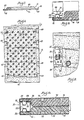
- a wall panel is shown as including a tubular metal frame 10 and an acoustical insert generally designated 11.
- the insert 11 is assembled to the frame 10 by means of locking members in the form of clip assemblies, generally designated 12 which removably couple to associated receptacles in the form of apertures 13 in the metal frame.
- the frame 10 includes upper and lower horizontal tubular elements 16, 17 which are welded respectively to the tops and bottoms of first and second upright side tubular members 18, 19 to form a rigid tubular metal frame.
- the apertures 13 are formed in the front surface of the upright tubular side members 18, 19; and it is understood that similar apertures are formed in the back surfaces of these frame members so that a similar acoustical insert (or other insert) may be assembled to the other side of the frame 10. Any such insert could be similar in construction to the one illustrated and to be described in more detail presently, so further description of it is not necessary for a complete understanding of the invention.
- the clip assembly 12 comprises a clip support generally designated 21 and best seen in Fig. 2, and a spring clip generally designated 22 in Figs. 3-5.
- the clip support 21 has a general channel shape including a generally flat front plate 25, a rear plate 26, and an interconnecting side portion 28. The top and bottom of the rear plate 26 are cut to form upper and lower bendable members or hinges 29.
- the clip supports are assembled to the panel by placing the clip support over the border and pressing the bendable members inwardly until the feet 30 are embedded in the panel, as seen in Fig. 9 and 10.
- the rear plate 26 includes a first generally rectangular die cut aperture or slot square 35 at one side of which a tab 36 is struck to extend outwardly.
- a second slot 38 is formed spaced from the slot 35.
- the slot 38 includes a generally rectangular slot portion 39 which is in lateral register with a side of the slot 35, and a lead-in slot portion 40 which extends at an acute included angle from the aperture 39 and is located on the side aperture 39 in which the aperture 35 is formed.
- the longer sides of the rectangular slot 40 are parallel to a diagonal of the square slot 35.
- the spring clip 22 includes five flat sides formed in a generally octagonal shape so as to provide lead-in surfaces 50, 51 for assembling the clip to one of the apertures 13, and retaining edges 53 for holding the clip assembled once it is inserted.
- the clip also includes a first laterally extending tab 54 which is sized to fit diagonally into the aperture 35 on the clip support 21 (as illustrated by the arrows in Fig. 3), and a second tab 55 which is sized to be received in the inclined slot 40 when assembling the clip 22 to the clip support 21.
- the tab 55 has a larger width than the slot 39 so that it connot be removed directly.
- the tab 54 is inserted into the aperture 35 with the tab extending diagonally across the aperture, as seen in Fig. 4.
- the tab 55 on the other side of the clip aligns with the slot 40, the axis of the slot 40 being parallel to the diagonal of the slot 35 (see Fig. 3).
- the clip is then rotated to bring the tab 55 of the clip in alignment with the slot 39.
- the outwardly extending tab 36 on the clip support prevents removal of the tab 54 from the slot 39.
- the clip is rotated to the assembled position, it is secured to the clip support, as illustrated in Figs. 5, 9 and 10.
- the acoustical panel includes a central body portion 60 and peripheral border 61, both of which are formed of pressed glass fiber in a single step.
- the mold is shaped (and additional layers are added) such that the density of the fiber in the peripheral border 61 is substantially greater than the density of the fiber in the central body portion 60, thereby providing rigidity to the overall panel.
- the thickness of the central body portion 60 is approximately three times that of the thickness of the peripheral border 61 (nominal 2.54 cm. and 0.89 cm., respectively). Portions of the peripheral border are compressed even further as to 63 (see Fig. 6) to accommodate the width the clip support 21 so that its exterior is flush with the outer surface of the border, as seen in Fig. 9.
- the front surface of the border, designated 70 is flush with the front surface 71 of the central body portion of the insert.
- the fabric may be extended around the sides of the border and attached to the rear of the insert by adhesive or staples.
- the perimeter of the panel preferably corresponds to the perimeter of the tubular frame 10, so that an observer's eye is met primarily with the uniform fabric covering, rather than any substantial portion of the frame.
- the outer surface of the body portion 60 of the glass fiber insert may have a series of indentations 76 formed in it to enhance sound absorption.
- the clip support When the clip 22 is assembled to the clip support 21, the clip support is placed in one of the recesses 63 with the clip extending rearwardly-that is toward the side on which the larger central body portion of the insert extends.
- the assembled clip is seen in Fig. 8.
- an insert is assembled to the frame by simply pushing the spring clips into associated, registered apertures 13 in the direction of the arrow 80. Assembly is facilitated by the lead-in surfaces 50, 51. The inserts are held by the retaining edge 53. When assembled, the insert, border, clip, clip support, and tubular upright frame member appears as shown in Fig. 10.
- the thickness of the border portion of the insert is substantially less than that of the central body portion. This permits the body portion to extend inwardly of, and be received within, the peripheral frame 10, as illustrated in Fig. 10.
- the peripheral border adds rigidity to the insert. Such ridigity has been achieved in the illustrated embodiment by pressing the glass fiber to a substantially greater density than that of the central body portion preferably at least five times the density of the body portion, if still greater rigidity is required, the border can be impregnated with resin which either cures chemically or sets thermally, but which adheres to the glass fibers to bind them together.
- an epoxy resin may be used.
Landscapes
- Physics & Mathematics (AREA)
- Acoustics & Sound (AREA)
- Engineering & Computer Science (AREA)
- Architecture (AREA)
- Electromagnetism (AREA)
- Civil Engineering (AREA)
- Structural Engineering (AREA)
- Building Environments (AREA)
Claims (5)
Applications Claiming Priority (2)
| Application Number | Priority Date | Filing Date | Title |
|---|---|---|---|
| US05/958,784 US4423573A (en) | 1978-11-08 | 1978-11-08 | Wall panel with removable acoustical insert |
| US958784 | 1997-10-27 |
Publications (3)
| Publication Number | Publication Date |
|---|---|
| EP0020619A1 EP0020619A1 (de) | 1981-01-07 |
| EP0020619A4 EP0020619A4 (de) | 1981-03-09 |
| EP0020619B1 true EP0020619B1 (de) | 1983-07-20 |
Family
ID=25501294
Family Applications (1)
| Application Number | Title | Priority Date | Filing Date |
|---|---|---|---|
| EP79901599A Expired EP0020619B1 (de) | 1978-11-08 | 1980-05-20 | Wandpaneel-konstruktion mit abnehmbarem akustischem paneel |
Country Status (5)
| Country | Link |
|---|---|
| US (1) | US4423573A (de) |
| EP (1) | EP0020619B1 (de) |
| JP (1) | JPS55500995A (de) |
| DE (1) | DE2965948D1 (de) |
| WO (1) | WO1980000985A1 (de) |
Cited By (2)
| Publication number | Priority date | Publication date | Assignee | Title |
|---|---|---|---|---|
| DE8809169U1 (de) * | 1988-07-16 | 1988-09-15 | Beitat, Lothar, 6335 Lahnau | Element zum Befestigen von armierten schallschluckenden Platten oder Schürzen an Trägern und zum Befestigen solcher Platten oder Schürzen miteinander |
| DE102010063488A1 (de) * | 2010-12-20 | 2012-06-21 | Haworth Gmbh | Raumgliederungssystem |
Families Citing this family (48)
| Publication number | Priority date | Publication date | Assignee | Title |
|---|---|---|---|---|
| DE3322360A1 (de) * | 1983-06-22 | 1985-01-03 | Kaefer Isoliertechnik Gmbh & Co Kg, 2800 Bremen | Schalldaemmung aus vorgefertigten elementen |
| US4876835A (en) * | 1984-09-10 | 1989-10-31 | Herman Miller, Inc. | Work space management system |
| US4685255A (en) * | 1984-09-10 | 1987-08-11 | Herman Miller, Inc. | Work space management system |
| US4702046A (en) * | 1985-11-08 | 1987-10-27 | General Communications, Inc. | Acoustical wall panel |
| US4914873A (en) * | 1987-03-05 | 1990-04-10 | Herman Miller, Inc. | Work environment system |
| US4901485A (en) * | 1989-04-06 | 1990-02-20 | National Gypsum Company | Acoustical panel |
| US5175969A (en) * | 1991-06-06 | 1993-01-05 | Steelcase Inc. | Partition panel |
| US5816001B1 (en) * | 1996-07-26 | 2000-06-06 | Steelcase Inc | Partition construction including interconnection system and removable covers |
| US5890325A (en) * | 1996-08-22 | 1999-04-06 | Steelcase Inc. | Reconfigurable system for subdividing building space and having minimal footprint |
| US5806258A (en) * | 1996-06-07 | 1998-09-15 | Haworth, Inc. | Wall panel system |
| US5802789B1 (en) * | 1996-12-17 | 2000-11-07 | Steelcase Inc | Partition construction including removable cover panels |
| US6209273B1 (en) | 1997-05-30 | 2001-04-03 | Steelcase Development Inc. | Panel wall construction |
| US6158178A (en) * | 1997-05-30 | 2000-12-12 | Steelcase Inc. | Panel wall construction |
| US5906079A (en) * | 1998-01-14 | 1999-05-25 | Steelcase, Inc. | Partition system with attached markerboard |
| US6082065A (en) * | 1998-08-10 | 2000-07-04 | Steelcase Development Inc. | Connector for partition system |
| AUPP588598A0 (en) | 1998-09-14 | 1998-10-08 | Colmark (Australia) Pty Ltd | Clip fastening system |
| AU722233B2 (en) * | 1998-09-14 | 2000-07-27 | Spanbilt (Australia) Pty Ltd | Clip fastening system for walls |
| US6256941B1 (en) | 1999-06-04 | 2001-07-10 | Haworth, Inc. | Pad for panel |
| US6490828B1 (en) | 2000-07-20 | 2002-12-10 | Steelcase Development Corporation | Partition wall system |
| US6805185B2 (en) | 2001-04-06 | 2004-10-19 | Steelcase Development Corporation | Cover panel attachment system for partitions |
| EP1395717A1 (de) * | 2001-06-15 | 2004-03-10 | Kimball International Inc. | Wandpaneelsystem, das sich vom boden bis zur decke erstreckt |
| US6698543B2 (en) | 2001-07-03 | 2004-03-02 | Golterman & Sabo, Inc. | Acoustical wall panels |
| US6684929B2 (en) * | 2002-02-15 | 2004-02-03 | Steelcase Development Corporation | Panel system |
| US6775953B2 (en) * | 2002-05-31 | 2004-08-17 | Hon Technology Inc. | Simplified wall panel |
| US7178300B2 (en) * | 2002-09-30 | 2007-02-20 | Krueger International, Inc. | Latch-type tile mounting system |
| US6968661B2 (en) | 2003-01-17 | 2005-11-29 | Krueger International, Inc. | Stiffener construction having a snap-on connector, for use with a wall panel shell in a wall system |
| US20060179765A1 (en) * | 2005-01-31 | 2006-08-17 | Howard Meghan L | Adaptable ceiling tile system |
| US20050211500A1 (en) * | 2004-03-26 | 2005-09-29 | Wendt Alan C | Fibrous faced ceiling panel |
| US7677182B2 (en) * | 2004-05-27 | 2010-03-16 | Steelcase Development Corporation | Two person work environment |
| US20080029336A1 (en) * | 2006-06-10 | 2008-02-07 | Patrick Sigler | Acoustic panel |
| US8176695B2 (en) * | 2006-11-06 | 2012-05-15 | Haworth, Inc. | Wall panel frame arrangement |
| US7856777B2 (en) * | 2006-11-06 | 2010-12-28 | Haworth, Inc. | Clip arrangement for wall panel tiles |
| US8033071B2 (en) * | 2007-07-03 | 2011-10-11 | Okamura Corporation | Partition panel and a method of assembling it |
| US8215081B2 (en) * | 2009-01-29 | 2012-07-10 | Krueger International, Inc. | Panel tile and top cap retention system |
| US20100243369A1 (en) * | 2009-03-31 | 2010-09-30 | Nuform Building Technologies Inc. | Highway noise barrier |
| CA2853141C (en) * | 2009-10-29 | 2015-12-15 | Krueger International, Inc. | Panel system |
| US10329759B2 (en) | 2012-09-17 | 2019-06-25 | Steelcase Inc. | Floor-to-ceiling partition wall assembly |
| CA2881683C (en) | 2012-09-17 | 2018-07-24 | Steelcase Inc. | Floor-to-ceiling partition wall assembly |
| US9032682B2 (en) | 2012-12-10 | 2015-05-19 | Target Brands, Inc. | Free-standing wall |
| KR101422076B1 (ko) * | 2013-01-25 | 2014-07-28 | 강종우 | 플랫타이 및 이 플랫타이와 비금속제 거푸집틀을 이용한 거푸집 설치방법 |
| KR101250860B1 (ko) * | 2013-02-05 | 2013-04-05 | 강종우 | 거푸집틀 및 이를 이용한 거푸집 설치방법 |
| WO2015148951A1 (en) | 2014-03-28 | 2015-10-01 | Steelcase Inc. | Transparent panel system for partitions |
| EP3219866B1 (de) * | 2016-03-18 | 2018-10-03 | STO SE & Co. KGaA | Vorrichtung zur beeinflussung der akustik eines innenraums |
| US11753818B1 (en) * | 2019-08-07 | 2023-09-12 | Kelly B. McKenna | Acoustic material frame and method |
| US12529223B2 (en) | 2019-08-07 | 2026-01-20 | Kelly B. McKenna | Acoustic material frame and method |
| EP3929369A1 (de) * | 2020-06-26 | 2021-12-29 | Corsair Memory, Inc. | Akustikplatte und -system |
| US20220335918A1 (en) * | 2021-04-20 | 2022-10-20 | Acoustical Fulfillment LLC | Adaptive Acoustical Treatment with Magnetic Coupling |
| US20230203805A1 (en) * | 2021-12-27 | 2023-06-29 | Calum W. Smeaton | Apparatus with Interchangeable Panels for Varying Acoustic and Esthetic Treatments or Effects |
Family Cites Families (8)
| Publication number | Priority date | Publication date | Assignee | Title |
|---|---|---|---|---|
| US1940969A (en) | 1928-10-06 | 1933-12-26 | Woodall Industries Inc | Wall panel |
| US2262426A (en) | 1940-01-30 | 1941-11-11 | Randall Company | Finishing panel mount |
| US2903815A (en) | 1956-11-02 | 1959-09-15 | United Carr Fastener Corp | Fastening device |
| US3077426A (en) | 1957-05-24 | 1963-02-12 | Owens Corning Fiberglass Corp | Acoustical panel |
| US3286412A (en) | 1964-02-13 | 1966-11-22 | Woodall Industries Inc | Panel and frame assembly |
| GB1495273A (en) * | 1974-04-29 | 1977-12-14 | Bestobell Aviat Prod Ltd | Acoustic barriers |
| US3998018A (en) * | 1975-03-31 | 1976-12-21 | Kaiser Cement & Gypsum Corporation | Wall panel mounting system |
| US4123879A (en) * | 1977-06-27 | 1978-11-07 | American Seating Company | Panel wall systems with modular component build-up |
-
1978
- 1978-11-08 US US05/958,784 patent/US4423573A/en not_active Expired - Lifetime
-
1979
- 1979-11-02 JP JP50205579A patent/JPS55500995A/ja active Pending
- 1979-11-02 DE DE7979901599T patent/DE2965948D1/de not_active Expired
- 1979-11-02 WO PCT/US1979/000981 patent/WO1980000985A1/en not_active Ceased
-
1980
- 1980-05-20 EP EP79901599A patent/EP0020619B1/de not_active Expired
Cited By (2)
| Publication number | Priority date | Publication date | Assignee | Title |
|---|---|---|---|---|
| DE8809169U1 (de) * | 1988-07-16 | 1988-09-15 | Beitat, Lothar, 6335 Lahnau | Element zum Befestigen von armierten schallschluckenden Platten oder Schürzen an Trägern und zum Befestigen solcher Platten oder Schürzen miteinander |
| DE102010063488A1 (de) * | 2010-12-20 | 2012-06-21 | Haworth Gmbh | Raumgliederungssystem |
Also Published As
| Publication number | Publication date |
|---|---|
| US4423573A (en) | 1984-01-03 |
| EP0020619A4 (de) | 1981-03-09 |
| WO1980000985A1 (en) | 1980-05-15 |
| DE2965948D1 (en) | 1983-08-25 |
| EP0020619A1 (de) | 1981-01-07 |
| JPS55500995A (de) | 1980-11-20 |
Similar Documents
| Publication | Publication Date | Title |
|---|---|---|
| US4423573A (en) | Wall panel with removable acoustical insert | |
| US3949827A (en) | Acoustical panel assembly | |
| US4731960A (en) | Molding strip assembly with reveal and shelving system for use in constructing flexible wall coverings | |
| US4702046A (en) | Acoustical wall panel | |
| US4185430A (en) | Interconnecting modular screen assembly | |
| US6263624B1 (en) | Skylight assembly | |
| US20030115817A1 (en) | Reinforced window shutter | |
| US4601146A (en) | Post cover for space dividing wall panel system | |
| US6863339B2 (en) | Composite part for a vehicle body | |
| CA2231158A1 (en) | Wall panels and joint structures | |
| US4637299A (en) | Vent opening for portable building wall | |
| US4561229A (en) | Modular screen assembly | |
| GB2258683A (en) | Door panel incorporating a strengthening perforated steel plate | |
| US4424654A (en) | Panel rigidizer | |
| US5465540A (en) | Facade structure for windows | |
| US20050193674A1 (en) | Locking laps for vinyl siding | |
| JP2816798B2 (ja) | 外装パネル | |
| JP2805842B2 (ja) | パネルの目地構造 | |
| JPH10140823A (ja) | コンクリート型枠 | |
| US20070079562A1 (en) | Ceiling tile assembly | |
| JPH02646Y2 (de) | ||
| JPH06490Y2 (ja) | 天井パネル | |
| JPH10131355A (ja) | 構造用パネル | |
| JPS6138304B2 (de) | ||
| JPS642935U (de) |
Legal Events
| Date | Code | Title | Description |
|---|---|---|---|
| PUAI | Public reference made under article 153(3) epc to a published international application that has entered the european phase |
Free format text: ORIGINAL CODE: 0009012 |
|
| AK | Designated contracting states |
Designated state(s): DE FR GB |
|
| 17P | Request for examination filed |
Effective date: 19801107 |
|
| RBV | Designated contracting states (corrected) |
Designated state(s): DE FR GB |
|
| GRAA | (expected) grant |
Free format text: ORIGINAL CODE: 0009210 |
|
| AK | Designated contracting states |
Designated state(s): DE FR GB |
|
| ET | Fr: translation filed | ||
| REF | Corresponds to: |
Ref document number: 2965948 Country of ref document: DE Date of ref document: 19830825 |
|
| PLBE | No opposition filed within time limit |
Free format text: ORIGINAL CODE: 0009261 |
|
| STAA | Information on the status of an ep patent application or granted ep patent |
Free format text: STATUS: NO OPPOSITION FILED WITHIN TIME LIMIT |
|
| 26N | No opposition filed | ||
| PGFP | Annual fee paid to national office [announced via postgrant information from national office to epo] |
Ref country code: FR Payment date: 19841108 Year of fee payment: 6 |
|
| PGFP | Annual fee paid to national office [announced via postgrant information from national office to epo] |
Ref country code: DE Payment date: 19841116 Year of fee payment: 6 |
|
| GBPC | Gb: european patent ceased through non-payment of renewal fee | ||
| PG25 | Lapsed in a contracting state [announced via postgrant information from national office to epo] |
Ref country code: FR Free format text: LAPSE BECAUSE OF NON-PAYMENT OF DUE FEES Effective date: 19870731 |
|
| PG25 | Lapsed in a contracting state [announced via postgrant information from national office to epo] |
Ref country code: DE Effective date: 19870801 |
|
| REG | Reference to a national code |
Ref country code: FR Ref legal event code: ST |
|
| PG25 | Lapsed in a contracting state [announced via postgrant information from national office to epo] |
Ref country code: GB Effective date: 19881118 |