EP0020791A1 - Dispositif de commande d'une valve disposée dans la conduite d'air de charge d'un moteur à combustion - Google Patents
Dispositif de commande d'une valve disposée dans la conduite d'air de charge d'un moteur à combustion Download PDFInfo
- Publication number
- EP0020791A1 EP0020791A1 EP79101815A EP79101815A EP0020791A1 EP 0020791 A1 EP0020791 A1 EP 0020791A1 EP 79101815 A EP79101815 A EP 79101815A EP 79101815 A EP79101815 A EP 79101815A EP 0020791 A1 EP0020791 A1 EP 0020791A1
- Authority
- EP
- European Patent Office
- Prior art keywords
- air
- line
- flap
- actuator according
- piston
- Prior art date
- Legal status (The legal status is an assumption and is not a legal conclusion. Google has not performed a legal analysis and makes no representation as to the accuracy of the status listed.)
- Granted
Links
- 238000002485 combustion reaction Methods 0.000 title claims abstract description 13
- 239000012528 membrane Substances 0.000 claims description 20
- 238000007789 sealing Methods 0.000 claims description 9
- 238000009423 ventilation Methods 0.000 claims description 9
- 238000011144 upstream manufacturing Methods 0.000 claims description 7
- 230000008878 coupling Effects 0.000 claims description 6
- 238000010168 coupling process Methods 0.000 claims description 6
- 238000005859 coupling reaction Methods 0.000 claims description 6
- 238000013459 approach Methods 0.000 claims description 5
- 230000002093 peripheral effect Effects 0.000 claims 1
- 239000007789 gas Substances 0.000 description 17
- 239000002184 metal Substances 0.000 description 6
- 238000000034 method Methods 0.000 description 4
- 230000008569 process Effects 0.000 description 4
- 230000000694 effects Effects 0.000 description 3
- 230000009471 action Effects 0.000 description 2
- 238000011109 contamination Methods 0.000 description 2
- 238000005192 partition Methods 0.000 description 2
- 230000035515 penetration Effects 0.000 description 2
- 238000003825 pressing Methods 0.000 description 2
- 241001136792 Alle Species 0.000 description 1
- 229910000831 Steel Inorganic materials 0.000 description 1
- 230000008901 benefit Effects 0.000 description 1
- 230000000903 blocking effect Effects 0.000 description 1
- 238000010276 construction Methods 0.000 description 1
- 230000003111 delayed effect Effects 0.000 description 1
- 230000005021 gait Effects 0.000 description 1
- 238000010438 heat treatment Methods 0.000 description 1
- 238000000926 separation method Methods 0.000 description 1
- 239000007858 starting material Substances 0.000 description 1
- 239000010959 steel Substances 0.000 description 1
- 230000007704 transition Effects 0.000 description 1
Images



Classifications
-
- F—MECHANICAL ENGINEERING; LIGHTING; HEATING; WEAPONS; BLASTING
- F02—COMBUSTION ENGINES; HOT-GAS OR COMBUSTION-PRODUCT ENGINE PLANTS
- F02D—CONTROLLING COMBUSTION ENGINES
- F02D23/00—Controlling engines characterised by their being supercharged
-
- F—MECHANICAL ENGINEERING; LIGHTING; HEATING; WEAPONS; BLASTING
- F02—COMBUSTION ENGINES; HOT-GAS OR COMBUSTION-PRODUCT ENGINE PLANTS
- F02B—INTERNAL-COMBUSTION PISTON ENGINES; COMBUSTION ENGINES IN GENERAL
- F02B33/00—Engines characterised by provision of pumps for charging or scavenging
- F02B33/32—Engines with pumps other than of reciprocating-piston type
- F02B33/42—Engines with pumps other than of reciprocating-piston type with driven apparatus for immediate conversion of combustion gas pressure into pressure of fresh charge, e.g. with cell-type pressure exchangers
-
- Y—GENERAL TAGGING OF NEW TECHNOLOGICAL DEVELOPMENTS; GENERAL TAGGING OF CROSS-SECTIONAL TECHNOLOGIES SPANNING OVER SEVERAL SECTIONS OF THE IPC; TECHNICAL SUBJECTS COVERED BY FORMER USPC CROSS-REFERENCE ART COLLECTIONS [XRACs] AND DIGESTS
- Y02—TECHNOLOGIES OR APPLICATIONS FOR MITIGATION OR ADAPTATION AGAINST CLIMATE CHANGE
- Y02T—CLIMATE CHANGE MITIGATION TECHNOLOGIES RELATED TO TRANSPORTATION
- Y02T10/00—Road transport of goods or passengers
- Y02T10/10—Internal combustion engine [ICE] based vehicles
- Y02T10/12—Improving ICE efficiencies
Definitions
- the invention relates to an actuator according to the preamble of claim 1.
- an air flap in the charge air line which closes at least until the diesel engine starts and at the latest when the idling speed is exceeded after the starting process for the entire subsequent operating time of the diesel engine until it is switched off is open.
- an air flap arranged and operated in this way is required, since otherwise, due to the transitions between charge air and exhaust gas circuits present here, exhaust gases flow into the charge air line during the first work cycles of the diesel engine and bring the diesel engine to a standstill again immediately can.
- an actuator for an air flap arranged in the charge air line of a diesel engine which is particularly charged by means of a pressure wave supercharger, has been proposed, which has a shut-off valve which leads into an admission line from a pressure oil line of the diesel engine to an admission space for a control piston actuating the air flap is arranged, which on the other hand is loaded by a constantly effective force, the shut-off valve in the opening direction by one in this switching direction
- the control piston which is loaded by the pressure in the charge air line against the force of a spring, can be actuated and can only be closed when there is no oil pressure, and the shut-off valve is controlled by the control piston and can only be closed when the control valve is in the rest position, in which the air flap is closed, in the absence of oil pressure.
- An advantageous embodiment according to the invention is that the air flap for its pivotable mounting in the charge air line is held on a shaft led out of the charge air line, to which at least one spring engages to rotate the shaft into the closed position of the air flap and which rotates in the opposite direction Shaft is connected to the open position of the air flap via a lever gear with at least one piston acted upon by the pressure of the intake air sucked in and / or by vacuum.
- a diesel engine not shown, is designated by 1.
- an intake line 3 leads to a charging device 4, which is connected to the engine 1 on the one hand via a charge air line 5 and on the other hand via an exhaust line 6.
- the exhaust gases can flow out of the charging device 4 to the atmosphere through a line 7.
- a controllable air flap 8 is arranged in the charge air line 5 and adjoins in a housing section 10 for receiving an actuating device for the air flap 8.
- the housing section 10 is connected to the air line 5 'for actuating the actuator, which branches off from the charge air line 5.
- the actuator described in more detail below controls the air flap in a rest (blocking) position in which the air passage through the charge air line 5 is blocked, and in a working (opening) position in which the charge air line 5 for passage is released from compressed air.
- a sniffer or bypass valve 11 is arranged behind the air flap 8, via which, when the air flap 8 is closed, atmospheric air is sucked in by the engine 1 from a certain negative pressure in the section of the charge air line 5 leading to the engine 1.
- the charging device 4 can be of any type, preferably it is a pressure wave charging device in which the exhaust energy contained in the former is used to compress the latter without strictly defined separation of exhaust gas and charging air.
- the mechanical drive of the charging device 4 required for this is not shown in FIG. 1.
- the two housing sections 9 and 10 show a cross section through the two housing sections 9 and 10 forming a housing unit for the air flap 8 and the actuator. It is clear that the two housing sections can also consist of separate housings which are flanged together.
- the housing section 9 consists of a tube section which is connected to the charge air line 5 with opposite flanges 12, 13 (FIG. 1).
- the central bore 34 in the shaft 27 is expanded to form an inner shoulder 35 at the other end 36 of the shaft 27 to a bore 37 into which the head 38 of a bolt engages, the shaft 39 of which extends through the bore 34 and with the air flap is tense.
- Derzenkopf 38 is supported with the interposition of a slotted washer 41 on the inner shoulder 35.
- the shaft 27 is rotatably mounted in a bore 42 in a housing partition 43 between the housing section 9 receiving the air flap 8 and the housing section 10 enclosing the actuator for the air flap.
- the shaft 27 extends transversely through the cylindrical interior 46 of the housing section 10, the shaft axis 39 coming to lie on a diameter in the central radial plane of the interior 46, the axis 47 of which is thus perpendicular to the shaft axis 39.
- the cylindrical interior 46 is closed on both ends by two housing covers 48 and 49.
- cover screws 50 which engage at their corners radially outside of the interior 46 in threaded holes in the housing walls through holes in the covers, not shown.
- the housing section 10 has a lateral opening 51 centered on the shaft axis, through which the shaft end 36 extends with play.
- a seal 55 is present between the lid edge 53 and the housing shoulder 52.
- the shaft end 36 is provided with an axial slot 65 for engaging the inner end 66 of a helically wound metal spring 67.
- the outer end of the metal spring 67 is held on the housing shoulder 52.
- the metal spring 67 not shown, which is a bimetallic spring in the present example, is preloaded such that when the engine is switched off and cooled to a certain minimum temperature after being switched off, the air flap 8 on the shaft 27 in its closed position, but in the other case in its holds open position.
- a sleeve-like coupling body 68 of depth a is held in the center in the cylindrical interior 46 of the housing section 10 by a parallel key 69 1 (FIG. 3) engaging in a shaft and a sleeve groove.
- the coupling body 68 which is elongate in cross section, is flattened symmetrically to a plane through the shaft axis on both sides, so that it has a wall thickness b in this plane which is substantially greater than the wall thickness c in a plane running perpendicular to it through the shaft axis.
- two opposing pistons 69 and 70 with ring seals 71 and 72 are slidably arranged in grooves 71 'and 72'.
- the essentially identical pistons 69 and 70 are arranged in the cylindrical interior 46 such that the lugs 73, 74 and 75, 76 are directed towards one another and at diametrically opposite points by pins 77 and 78 with the elongated body running parallel to the shaft 27 68 are articulated.
- both pins 77 are in front view and only one of the two approaches 73 and 75 recognizable by one of the pistons 70 and 71.
- a bore 79 which leads into the cylindrical interior 46 between the two pistons 70, 71.
- the bore 79 connects to the chamber for the air flap 8 in the flow direction in front of the air flap.
- Openings 80, 81 are located in each of the two housing covers 48 and 49, which are ventilation holes of the piston tops not acted upon by the boost pressure, and which are closed off by air filters 82, 83 against contamination of the interior 46.
- the cover 48 there is also a bore 85 into which a screw 84 can be screwed. and can be set at a certain depth of penetration into the cylindrical interior 46 in order to have an adjustable stroke limit stop for the pistons 69 and 70.
- the circumferential surfaces of the pistons 69 and 70 are slightly spherical or spherical, so that they can adjust their movements without jamming in the cylindrical space 46 at small angles to the piston axis.
- the pistons 69 and 70 wobble in opposite directions about their common axis, the shaft 27 being rotated and the pins 77 and 78 being rotated in circular arcs around the shaft axis.
- the sealing rings 71 and 72 remain pressed tightly against the cylinder inner wall of the space 46 during the wobbling movement of the pistons 69, 70.
- the sealing rings have on their inner circumferences dovetail-shaped profiles which form sealing lips which, in the manner of non-return flaps, bear against axially opposite groove walls of the grooves 71 ', 72'.
- the maximum inclined positions of the pistons 69 and 70 are chosen to be so small with respect to their axes that pressing out of the sealing rings 71 and 72 from their grooves 71 'and 72' is reliably avoided.
- the first ignitions of the diesel engine 1 pushes exhaust gases into the exhaust gas line 6-out with overpressure. These exhaust gases reach the charging device 4 and begin to operate the pressure wave process. If the charging device 4 is designed as a pressure wave device, as a result of the closed position of the air flap 8, despite the connection in the charging device 4 from the exhaust gas line 6 to the charge air line 5, no exhaust gas can be sucked into the latter, which quickly suffocates the diesel engine 1 and bring it to a standstill would. Rather, the exhaust gas is kept away from the charge air inlet of the diesel engine 1 by the closed air flap and is expelled through the line 7.
- the air flap 8 is held in the open position by the heated bimetallic spring 67, although the charge pressure of the charge air disappears and thus the pistons 69 and 70 are no longer pressurized.
- the bimetallic spring 67 can be designed such that it still exerts the necessary closing force on the shaft 27 up to a temperature of 40 ° C and, at a temperature above 90 ° C, exerts an opposite force on the shaft 27 in the direction of the opening of the air flap 8 .
- the air flap 8 remains in the open position under the action of the bimetal spring 67 until the bimetal spring reaches a temperature e.g. has fallen below 40 ° C. At this temperature, the engine has cooled to such an extent that the air flap must be closed during the start-up phase to restart. However, this is not the case if the switched-off motor is still sufficiently warm after a longer operating time and the bimetal spring accordingly still has a temperature as a result of which the air flap 8 is controlled into the open position. If the switched-off engine is started again, which has not yet cooled below a certain temperature, the air flap 8 is open and the engine can thus be ramped up to its full power more quickly than if the air flap 8 first had to be opened.
- the piston interior 46 ' is pressurized via the bore 79 with compressed air from the part of the charge air line 5 located upstream in front of the flap 8, as a result of which the opening movement of the flap 8 is initiated.
- the pistons 69, 70 move in opposite directions, the outside of the piston 70 lifts a spring-loaded valve 102 arranged in the cover 48 and opens the opening 101.
- the piston outer space 46 ′′ is connected via a diaphragm valve 106 and a vacuum line 100 to a vacuum source (not shown).
- This vacuum source can be the vacuum pump of the engine brake booster.
- the diaphragm valve 106 is shown in the rest position, that is to say when the internal combustion engine is switched off.
- the valve 106b actuated via the spring-loaded membrane 106a keeps a vent line 104 opening into the atmosphere open and the vacuum line 100 connected to the vacuum source closed.
- the upper side of the membrane is subjected to negative pressure from the suction line 3 arranged upstream of the charging device 4 via an air line 107.
- the underside of the membrane is permanently vented via the bore 109.
- the valve 106b attached to the membrane 106a is raised, closes the vent 104 and releases the vacuum line 100.
- the vacuum reaches the piston chamber 46 ′′ via the raised valve 102 and now supports the effect of the piston interior 46 ′. pressurizing pressure such that the flap 8 remains fully open at all times regardless of this pressure fluctuating depending on the engine load.
- FIG. 5 shows a further embodiment in which, like that in FIG. 4, the initial movement of the flap 8 is controlled by boost pressure, while the actuating device is essentially vacuum-actuated and the suction pressure upstream of the charger 4 is used as a control variable (not shown in Fig. 5).
- the boost pressure does not act on the piston interior 46 1 , but initiates the opening movement by directly applying pressure to the flap 8.
- the flap 8 is mounted eccentrically, ie its pivotable mounting is arranged eccentrically in relation to the flap surface by the amount e. This eccentricity is chosen in such a way that, due to the asymmetrical loading with the boost pressure, the flap 8 is at least pivoted out and the opening movement is initiated, which is then, as in the embodiment according to FIG. 4, supported by the vacuum pull on the pistons 69, 70.
- the design has the advantage over the previous examples that the piston interior 46 'and in particular the sealing surfaces are not exposed to any risk of contamination from unclean charge air.
- FIG. 6 A further simplification is shown in FIG. 6.
- the outer piston chamber 46 "is directly connected without any charge air influence A vacuum is applied, ie the spring-loaded valve 102 that initially closes off the opening 101 can be dispensed with.
- This solution is appropriate wherever engine operation with high pressure in front of closed flap 8 and the resulting strong heating of the charger by hot engine exhaust gases is possible.
- the spring 67 can be designed so that if the charger fails, a possible high exhaust gas pressure in the charge air line can partially open the flap. Not enough to suffocate the internal combustion engine because it is mixed with fresh air drawn in from the bypass valve 11, but enough to allow exhaust gas circulation. In this gait, the speed of the internal combustion engine will decrease, the exhaust gas pressure drops, the flap 8 closes completely and the internal combustion engine continues to run as a naturally aspirated engine.
- Fig. 7 shows an actuator control in which the flap 8 is only kept open with the aid of charge air.
- Charge air reaches the outer piston chamber 46 "via line 5 'via a spring-loaded check valve 103.
- the pistons 69, 70 are not opposed to each other in relation to the flap opening, but run towards one another. Because of the mode of operation of the check valve the greatest pressure occurring in the charge air line is stored in the piston chamber 46 "and causes the permanent opening of the flap 8 against the restoring force of the correspondingly dimensioned spring 67.
- the piston chamber must be vented (104), which is via a spring-loaded Diaphragm valve 105 occurs automatically when the negative pressure (107) controlling the diaphragm fails from the suction line 3 arranged upstream of the charging device 4, for example when the charger is at a standstill.
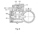
- a vacuum actuated actuator in which the control of the vacuum supply in contrast to the embodiments according to 4, 5, 6 and 7 happen via a diaphragm valve charged with boost pressure from the charge air line 5.
- the spring-loaded membrane lo6 ' actuates the double-acting valve 102', which either connects the vent line 104 or the vacuum line 100 to the piston chamber 46 ".
- the membrane valve is designed such that when the vacuum supply is open, the vacuum also acts on the underside of the membrane and thus the effect of the over line 110 to the top of the diaphragm supports the charge pressure. If the boost pressure collapses, the vacuum on the underside of the diaphragm is sufficient to keep the vent line closed. Only when the vacuum source is shut down when the engine is switched off does the vacuum escape from the piston chamber 46 'and the like Flap 8. In this variant, engine operation with the flap closed is possible up to a certain control pressure, ie charge air pressure.
- the piston interior 46 ' is permanently connected to the atmosphere via a vent 108.
- FIG. 9 shows a further vacuum-actuated actuating device, in which the vacuum supply is controlled, as in the embodiment according to FIG. 8, via a diaphragm valve 106 'which is charged with boost pressure.
- the spring-loaded membrane 106 ' actuates a single-acting valve 102 "which either closes the vacuum line 100, from the piston chamber 46", or connects it to the piston chamber 46 ".
- the strengths of the springs 106d and 67 'under the membrane 106' or on the flap shaft 27 are matched to one another in such a way that when the negative pressure escapes from the piston chamber 46 "due to the force of the spring 67 ', the pistons 69, 70 move apart thereby guiding the flap over the shaft into its closed position before the valve 102 "is pulled into its closed position by the spring 106d.
- Valve 102 ′′ could also be briefly held in the open position by the charge air pressure above diaphragm 106 ′ in order to escape the vacuum from piston space 46 ′′, the charge air pressure then being reduced in a delayed manner with respect to the vacuum via a throttle check valve (not shown) in line 110.
- the pistons 69 and 70 need not necessarily be designed as a wobble piston.
- more complex solutions are readily available to the person skilled in the art, in which the approaches 73, 74 and 75, 76 engage the pistons in an articulated manner.
- the clutch body 68 can also be integral with the shaft 27 be connected.
Landscapes
- Engineering & Computer Science (AREA)
- Chemical & Material Sciences (AREA)
- Combustion & Propulsion (AREA)
- Mechanical Engineering (AREA)
- General Engineering & Computer Science (AREA)
- Control Of Throttle Valves Provided In The Intake System Or In The Exhaust System (AREA)
- Supercharger (AREA)
- Output Control And Ontrol Of Special Type Engine (AREA)
Priority Applications (10)
| Application Number | Priority Date | Filing Date | Title |
|---|---|---|---|
| EP79101815A EP0020791B1 (fr) | 1979-06-08 | 1979-06-08 | Dispositif de commande d'une valve disposée dans la conduite d'air de charge d'un moteur à combustion |
| DE7979101815T DE2967516D1 (en) | 1979-06-08 | 1979-06-08 | Device for controlling a valve disposed in the charge air conduit of a combustion engine |
| BR8008707A BR8008707A (pt) | 1979-06-08 | 1980-05-23 | Dispositivo para uma valvula de ar disposta do conduto do ar de carga de um motor de combustao interna |
| DE80DE8000078T DE3047540D2 (en) | 1979-06-08 | 1980-05-23 | Device for regulating a valve disposed in the air charge duct of a combustion engine |
| JP50111280A JPS56501733A (fr) | 1979-06-08 | 1980-05-23 | |
| DE19808033545 DE8033545U1 (de) | 1979-06-08 | 1980-05-23 | Stellgeraet fuer eine in der ladeluftleitung eines verbrennungsmotors angeordnete luftklappe |
| US06/232,025 US4414952A (en) | 1979-06-08 | 1980-05-23 | Actuator for an air valve placed in the boost air duct of an IC engine |
| AT904980A ATA904980A (de) | 1979-06-08 | 1980-05-23 | Stellgeraet fuer eine luftklappe in der ladeluftleitung eines verbrennungsmotors |
| PCT/DE1980/000078 WO1980002725A1 (fr) | 1979-06-08 | 1980-05-23 | Dispositif de reglage pour une soupape disposee dans la conduite d'air de charge d'un moteur a combustion |
| CA353,581A CA1129281A (fr) | 1979-06-08 | 1980-06-09 | Dispositif de positionnement du papillon dans un collecteur d'admission d'un moteur a combustion interne |
Applications Claiming Priority (1)
| Application Number | Priority Date | Filing Date | Title |
|---|---|---|---|
| EP79101815A EP0020791B1 (fr) | 1979-06-08 | 1979-06-08 | Dispositif de commande d'une valve disposée dans la conduite d'air de charge d'un moteur à combustion |
Publications (2)
| Publication Number | Publication Date |
|---|---|
| EP0020791A1 true EP0020791A1 (fr) | 1981-01-07 |
| EP0020791B1 EP0020791B1 (fr) | 1985-09-25 |
Family
ID=8186132
Family Applications (1)
| Application Number | Title | Priority Date | Filing Date |
|---|---|---|---|
| EP79101815A Expired EP0020791B1 (fr) | 1979-06-08 | 1979-06-08 | Dispositif de commande d'une valve disposée dans la conduite d'air de charge d'un moteur à combustion |
Country Status (7)
| Country | Link |
|---|---|
| US (1) | US4414952A (fr) |
| EP (1) | EP0020791B1 (fr) |
| JP (1) | JPS56501733A (fr) |
| BR (1) | BR8008707A (fr) |
| CA (1) | CA1129281A (fr) |
| DE (2) | DE2967516D1 (fr) |
| WO (1) | WO1980002725A1 (fr) |
Cited By (4)
| Publication number | Priority date | Publication date | Assignee | Title |
|---|---|---|---|---|
| DE3325393A1 (de) * | 1983-07-14 | 1985-01-24 | Mtu Motoren- Und Turbinen-Union Friedrichshafen Gmbh, 7990 Friedrichshafen | Dieselbrennkraftmaschine |
| EP0205843A1 (fr) * | 1985-06-26 | 1986-12-30 | BBC Brown Boveri AG | Moteur à combustion interne comprenant un compresseur à ondes de pression |
| EP0235609A1 (fr) * | 1986-02-28 | 1987-09-09 | BBC Brown Boveri AG | Turbochargeur à ondes de pression |
| US4838234A (en) * | 1987-04-16 | 1989-06-13 | Bbc Brown Boveri Ag | Free-running pressure wave supercharger |
Families Citing this family (4)
| Publication number | Priority date | Publication date | Assignee | Title |
|---|---|---|---|---|
| DE3564601D1 (en) * | 1984-03-27 | 1988-09-29 | Mazda Motor | Engine intake system having a supercharger |
| US20070163257A1 (en) * | 2006-01-19 | 2007-07-19 | Steed Leen D | Inline turbo blow off valve |
| US10087857B2 (en) | 2016-09-13 | 2018-10-02 | Ford Global Technologies, Llc | Secondary system and method for controlling an engine |
| DE102018111738A1 (de) * | 2018-05-16 | 2019-11-21 | Volkswagen Ag | Verfahren zur Reduzierung der Partikelemissionen bei einem Kaltstart eines Verbrennungsmotors |
Citations (5)
| Publication number | Priority date | Publication date | Assignee | Title |
|---|---|---|---|---|
| US2853987A (en) * | 1957-09-19 | 1958-09-30 | Ite Circuit Breaker Ltd | Diesel engine supercharged by the aerodynamic wave machine |
| CH378595A (de) * | 1960-08-30 | 1964-06-15 | Bbc Brown Boveri & Cie | Brennkraftmaschine mit einem als Aufladegerät wirkenden Druckaustauscher |
| CH399077A (de) * | 1960-03-11 | 1966-03-31 | Power Jets Research And Dev Li | Kraftanlage, die eine Kolbenkraftmaschine und einen Druckaustauscher aufweist |
| FR2337257A1 (fr) * | 1975-12-31 | 1977-07-29 | Bbc Brown Boveri & Cie | Procede pour le demarrage d'un moteur a combustion suralimente et dispositif pour la realisation de ce procede |
| DE2631257A1 (de) * | 1976-07-12 | 1978-01-26 | Bbc Brown Boveri & Cie | Stellgeraet fuer eine in der ladeluftleitung eines dieselmotors angeordnete luftklappe |
Family Cites Families (1)
| Publication number | Priority date | Publication date | Assignee | Title |
|---|---|---|---|---|
| GB895808A (en) * | 1960-03-11 | 1962-05-09 | Power Jets Res & Dev Ltd | Improvements in or relating to supercharging reciprocating internal-combustion engines |
-
1979
- 1979-06-08 EP EP79101815A patent/EP0020791B1/fr not_active Expired
- 1979-06-08 DE DE7979101815T patent/DE2967516D1/de not_active Expired
-
1980
- 1980-05-23 DE DE80DE8000078T patent/DE3047540D2/de not_active Expired
- 1980-05-23 JP JP50111280A patent/JPS56501733A/ja active Pending
- 1980-05-23 BR BR8008707A patent/BR8008707A/pt unknown
- 1980-05-23 US US06/232,025 patent/US4414952A/en not_active Expired - Fee Related
- 1980-05-23 WO PCT/DE1980/000078 patent/WO1980002725A1/fr not_active Ceased
- 1980-06-09 CA CA353,581A patent/CA1129281A/fr not_active Expired
Patent Citations (5)
| Publication number | Priority date | Publication date | Assignee | Title |
|---|---|---|---|---|
| US2853987A (en) * | 1957-09-19 | 1958-09-30 | Ite Circuit Breaker Ltd | Diesel engine supercharged by the aerodynamic wave machine |
| CH399077A (de) * | 1960-03-11 | 1966-03-31 | Power Jets Research And Dev Li | Kraftanlage, die eine Kolbenkraftmaschine und einen Druckaustauscher aufweist |
| CH378595A (de) * | 1960-08-30 | 1964-06-15 | Bbc Brown Boveri & Cie | Brennkraftmaschine mit einem als Aufladegerät wirkenden Druckaustauscher |
| FR2337257A1 (fr) * | 1975-12-31 | 1977-07-29 | Bbc Brown Boveri & Cie | Procede pour le demarrage d'un moteur a combustion suralimente et dispositif pour la realisation de ce procede |
| DE2631257A1 (de) * | 1976-07-12 | 1978-01-26 | Bbc Brown Boveri & Cie | Stellgeraet fuer eine in der ladeluftleitung eines dieselmotors angeordnete luftklappe |
Cited By (5)
| Publication number | Priority date | Publication date | Assignee | Title |
|---|---|---|---|---|
| DE3325393A1 (de) * | 1983-07-14 | 1985-01-24 | Mtu Motoren- Und Turbinen-Union Friedrichshafen Gmbh, 7990 Friedrichshafen | Dieselbrennkraftmaschine |
| EP0205843A1 (fr) * | 1985-06-26 | 1986-12-30 | BBC Brown Boveri AG | Moteur à combustion interne comprenant un compresseur à ondes de pression |
| CH667696A5 (de) * | 1985-06-26 | 1988-10-31 | Bbc Brown Boveri & Cie | Verbrennungsmotor mit einem druckwellenlader. |
| EP0235609A1 (fr) * | 1986-02-28 | 1987-09-09 | BBC Brown Boveri AG | Turbochargeur à ondes de pression |
| US4838234A (en) * | 1987-04-16 | 1989-06-13 | Bbc Brown Boveri Ag | Free-running pressure wave supercharger |
Also Published As
| Publication number | Publication date |
|---|---|
| DE3047540D2 (en) | 1982-02-11 |
| US4414952A (en) | 1983-11-15 |
| JPS56501733A (fr) | 1981-11-26 |
| WO1980002725A1 (fr) | 1980-12-11 |
| DE2967516D1 (en) | 1985-10-31 |
| BR8008707A (pt) | 1981-04-28 |
| CA1129281A (fr) | 1982-08-10 |
| EP0020791B1 (fr) | 1985-09-25 |
Similar Documents
| Publication | Publication Date | Title |
|---|---|---|
| DE1628144C3 (de) | Saugdrosselsteuereinrichtung | |
| DE10230108B4 (de) | Vorrichtung zum Verstellen des Hubs eines von einer Nockenwelle betätigten Ventils | |
| DE69219436T2 (de) | Brennkraftmaschine mit einer kontinuierlichen Bremsvorrichtung, insbesondere für Nutzfahrzeuge | |
| DE2758749C2 (de) | Auspuff-Bremsvorrichtung | |
| DE3142230C2 (de) | Einrichtung zur Leistungsanpassung eines Mehrzylinder-Kältemittelkompressors | |
| EP0033372A1 (fr) | Système de freinage pour moteurs à combustion interne à soupapes | |
| DE1451904B2 (de) | Regelvorrichtung fuer das abblasventil einer gasturbine insbesondere einer abgasturbine einer kolbenbrennkraft maschine | |
| DE2542312B2 (de) | Vorrichtung zum pneumatischen Bremsen und Wiederanlassen in Gegendrehrichtung für einen Dieselmotor | |
| DE3326133A1 (de) | Aufgeladener motor mit selbstzuendung | |
| DE102008063604A1 (de) | Ventileinrichtung und Brennkraftmaschinensystem | |
| EP0576415A1 (fr) | Soupape de contrôle de l'aspiration | |
| WO2021122046A1 (fr) | Dispositif d'actionnement de soupape pour actionner au moins deux soupapes d'échange de gaz d'un moteur à combustion interne, procédé de fonctionnement d'un tel dispositif d'actionnement de soupape et moteur à combustion interne | |
| EP0020791A1 (fr) | Dispositif de commande d'une valve disposée dans la conduite d'air de charge d'un moteur à combustion | |
| DE4302732C2 (de) | Steuereinrichtung für einen Ventilantrieb einer Brennkraftmaschine | |
| DE1932352B2 (de) | Drehschrauber mit zwei gleichachsig angeordneten druckluftmotoren | |
| DE2037705C3 (de) | Einrichtung zur Verringerung des Ausstoßes giftiger Abgasbestandteile bei Fahrzeug-Brennkraftmaschinen | |
| DE1287459B (fr) | ||
| DE19600536C2 (de) | Vorrichtung zur variablen Steuerung eines Einlaßventils | |
| DE1751909A1 (de) | Dosiereinrichtung fuer eine Brennstoffeinspritzpumpe | |
| DE2264237A1 (de) | Motor | |
| DE2509625A1 (de) | Betaetigungseinrichtung fuer die luftklappe eines vergasers | |
| DE112015005256B4 (de) | Ventilvorrichtung | |
| DE2631257C3 (de) | Stellgerät für eine in der Ladeluftleitung eines Dieselmotors angeordnete Luftklappe | |
| DE1952728B2 (de) | Bypass-ventileinrichtung fuer die nutzleistungsturbine einer gasturbinenanlage | |
| DE2149928A1 (de) | Kompressor |
Legal Events
| Date | Code | Title | Description |
|---|---|---|---|
| PUAI | Public reference made under article 153(3) epc to a published international application that has entered the european phase |
Free format text: ORIGINAL CODE: 0009012 |
|
| AK | Designated contracting states |
Designated state(s): BE CH DE FR GB IT NL SE |
|
| 17P | Request for examination filed |
Effective date: 19810701 |
|
| RAP1 | Party data changed (applicant data changed or rights of an application transferred) |
Owner name: BBC AKTIENGESELLSCHAFT BROWN, BOVERI & CIE. Owner name: KNORR-BREMSE GMBH |
|
| ITF | It: translation for a ep patent filed | ||
| GRAA | (expected) grant |
Free format text: ORIGINAL CODE: 0009210 |
|
| AK | Designated contracting states |
Designated state(s): BE CH DE FR GB IT NL SE |
|
| PG25 | Lapsed in a contracting state [announced via postgrant information from national office to epo] |
Ref country code: NL Effective date: 19850925 Ref country code: BE Effective date: 19850925 |
|
| PG25 | Lapsed in a contracting state [announced via postgrant information from national office to epo] |
Ref country code: SE Effective date: 19850930 |
|
| REF | Corresponds to: |
Ref document number: 2967516 Country of ref document: DE Date of ref document: 19851031 |
|
| REG | Reference to a national code |
Ref country code: GB Ref legal event code: 732 |
|
| RAP2 | Party data changed (patent owner data changed or rights of a patent transferred) |
Owner name: BBC AKTIENGESELLSCHAFT BROWN, BOVERI & CIE. Owner name: KNORR-BREMSE AG |
|
| ET | Fr: translation filed | ||
| REG | Reference to a national code |
Ref country code: CH Ref legal event code: PUEA Free format text: KNORR-BREMSE AG |
|
| ITPR | It: changes in ownership of a european patent |
Owner name: FUSIONI;KNORR - BREMSE AG |
|
| NLV1 | Nl: lapsed or annulled due to failure to fulfill the requirements of art. 29p and 29m of the patents act | ||
| REG | Reference to a national code |
Ref country code: FR Ref legal event code: CD |
|
| PLBE | No opposition filed within time limit |
Free format text: ORIGINAL CODE: 0009261 |
|
| STAA | Information on the status of an ep patent application or granted ep patent |
Free format text: STATUS: NO OPPOSITION FILED WITHIN TIME LIMIT |
|
| 26N | No opposition filed | ||
| PG25 | Lapsed in a contracting state [announced via postgrant information from national office to epo] |
Ref country code: CH Effective date: 19890630 |
|
| REG | Reference to a national code |
Ref country code: CH Ref legal event code: PL |
|
| PGFP | Annual fee paid to national office [announced via postgrant information from national office to epo] |
Ref country code: FR Payment date: 19900502 Year of fee payment: 12 |
|
| PGFP | Annual fee paid to national office [announced via postgrant information from national office to epo] |
Ref country code: GB Payment date: 19900504 Year of fee payment: 12 |
|
| ITTA | It: last paid annual fee | ||
| PG25 | Lapsed in a contracting state [announced via postgrant information from national office to epo] |
Ref country code: GB Effective date: 19910608 |
|
| GBPC | Gb: european patent ceased through non-payment of renewal fee | ||
| PG25 | Lapsed in a contracting state [announced via postgrant information from national office to epo] |
Ref country code: FR Effective date: 19920228 |
|
| REG | Reference to a national code |
Ref country code: FR Ref legal event code: ST |
|
| PGFP | Annual fee paid to national office [announced via postgrant information from national office to epo] |
Ref country code: DE Payment date: 19950818 Year of fee payment: 17 |
|
| PG25 | Lapsed in a contracting state [announced via postgrant information from national office to epo] |
Ref country code: DE Effective date: 19970301 |