EP0020932A1 - System zur Verarbeitung und Anzeige von Texten - Google Patents
System zur Verarbeitung und Anzeige von Texten Download PDFInfo
- Publication number
- EP0020932A1 EP0020932A1 EP80102238A EP80102238A EP0020932A1 EP 0020932 A1 EP0020932 A1 EP 0020932A1 EP 80102238 A EP80102238 A EP 80102238A EP 80102238 A EP80102238 A EP 80102238A EP 0020932 A1 EP0020932 A1 EP 0020932A1
- Authority
- EP
- European Patent Office
- Prior art keywords
- character
- characters
- storage means
- displayed
- data
- Prior art date
- Legal status (The legal status is an assumption and is not a legal conclusion. Google has not performed a legal analysis and makes no representation as to the accuracy of the status listed.)
- Granted
Links
Images







Classifications
-
- G—PHYSICS
- G06—COMPUTING OR CALCULATING; COUNTING
- G06F—ELECTRIC DIGITAL DATA PROCESSING
- G06F40/00—Handling natural language data
- G06F40/10—Text processing
- G06F40/166—Editing, e.g. inserting or deleting
-
- G—PHYSICS
- G09—EDUCATION; CRYPTOGRAPHY; DISPLAY; ADVERTISING; SEALS
- G09G—ARRANGEMENTS OR CIRCUITS FOR CONTROL OF INDICATING DEVICES USING STATIC MEANS TO PRESENT VARIABLE INFORMATION
- G09G1/00—Control arrangements or circuits, of interest only in connection with cathode-ray tube indicators; General aspects or details, e.g. selection emphasis on particular characters, dashed line or dotted line generation; Preprocessing of data
- G09G1/06—Control arrangements or circuits, of interest only in connection with cathode-ray tube indicators; General aspects or details, e.g. selection emphasis on particular characters, dashed line or dotted line generation; Preprocessing of data using single beam tubes, e.g. three-dimensional or perspective representation, rotation or translation of display pattern, hidden lines, shadows
- G09G1/14—Control arrangements or circuits, of interest only in connection with cathode-ray tube indicators; General aspects or details, e.g. selection emphasis on particular characters, dashed line or dotted line generation; Preprocessing of data using single beam tubes, e.g. three-dimensional or perspective representation, rotation or translation of display pattern, hidden lines, shadows the beam tracing a pattern independent of the information to be displayed, this latter determining the parts of the pattern rendered respectively visible and invisible
- G09G1/18—Control arrangements or circuits, of interest only in connection with cathode-ray tube indicators; General aspects or details, e.g. selection emphasis on particular characters, dashed line or dotted line generation; Preprocessing of data using single beam tubes, e.g. three-dimensional or perspective representation, rotation or translation of display pattern, hidden lines, shadows the beam tracing a pattern independent of the information to be displayed, this latter determining the parts of the pattern rendered respectively visible and invisible a small local pattern covering only a single character, and stepping to a position for the following character, e.g. in rectangular or polar co-ordinates, or in the form of a framed star
-
- G—PHYSICS
- G09—EDUCATION; CRYPTOGRAPHY; DISPLAY; ADVERTISING; SEALS
- G09G—ARRANGEMENTS OR CIRCUITS FOR CONTROL OF INDICATING DEVICES USING STATIC MEANS TO PRESENT VARIABLE INFORMATION
- G09G5/00—Control arrangements or circuits for visual indicators common to cathode-ray tube indicators and other visual indicators
- G09G5/22—Control arrangements or circuits for visual indicators common to cathode-ray tube indicators and other visual indicators characterised by the display of characters or indicia using display control signals derived from coded signals representing the characters or indicia, e.g. with a character-code memory
- G09G5/222—Control of the character-code memory
-
- G—PHYSICS
- G09—EDUCATION; CRYPTOGRAPHY; DISPLAY; ADVERTISING; SEALS
- G09G—ARRANGEMENTS OR CIRCUITS FOR CONTROL OF INDICATING DEVICES USING STATIC MEANS TO PRESENT VARIABLE INFORMATION
- G09G5/00—Control arrangements or circuits for visual indicators common to cathode-ray tube indicators and other visual indicators
- G09G5/42—Control arrangements or circuits for visual indicators common to cathode-ray tube indicators and other visual indicators characterised by the display of patterns using a display memory without fixed position correspondence between the display memory contents and the display position on the screen
Definitions
- the present invention relates to a text processing and display system and, more particularly, to a text processing and display system which uses sequential storage means storing the coded representations of the characters to be displayed in a sequence of storage locations spatially corresponding to the positions of the characters to be displayed on the display device.
- step (4) re-typing it using the coarse draft edited as a source of information; (4) re-editing to be sure of the correction and the aesthetic presentation; (5) re-type as required by step (4) and final re-edition to be sure that the final copy is correct.
- the prior art proposes and uses several devices which reduce the time lost for re-typing and re-editing of documents.
- a traditional approach of the prior art consists in recording the information typed with the machine on a secondary support, for example a magnetic support, which is selectively used by the typist who, using his typewriter, prints automatically output the information contained in the first draft with all the changes made to the edition.
- this traditional approach has been replaced by word processing systems which use cathode ray tube (CRT) displays, or the like, which display the information entered in the word processing system, for example by keyboard.
- CTR cathode ray tube
- the input data is displayed and the operator can make corrections to the data displayed. These corrections include, of course, the entry of new data, the deletion of existing data or the insertion of new data.
- the fundamental object of the present invention is therefore a text processing and display system in which the format of a section, or any block of displayed data can be modified.
- the text processing and display system of the present invention comprises a display device which simultaneously displays a block, or a page, comprising several lines of alphanumeric characters according to orderly display position lines, a matrix storage means for storing data representing the positions of the characters to be displayed, sequential access storage means for storing coded representations of the characters to be displayed in a succession of positions of storage corresponding spatially to the positions of the characters of the display unit, a repetitive scanning means for scanning the positions of the characters displayed in successive lines on the display device, a means of reading the locations of the matrix storage means, a means sequential access to the coded representations of each character to be displayed from the sequential storage means in synchronization with the scanning means, and means for applying to the display device signals which represent the whole character to be displayed at a display position before moving the scanning means to the next display position so that each character is completely refreshed before moving on to the next character.
- the system makes it possible to define the spatial limits of a section of the stored coded representations corresponding to the selected spatial limits of a section or of a block of alphanumeric characters, by inserting coded data designating an initial alphanumeric character of the selected section in the sequential storage means immediately before the coded representations of the characters, and inserting coded data designating a final alphanumeric character of the selected section into the sequential storage means immediately after the coded representations of the characters.
- the system also makes it possible to modify the spatial organization of the section of characters displayed by modifying the spatial organization of the coded representations of the characters of the sequential storage means between the data designating these initial and final positions.
- the practical implementation of the present invention involves an organization of sequential access memory for storing coded representations of a block, or of a page, carrying alphanumeric characters displayed on a CRT cathode ray tube.
- sequential access memory the coded representations of the displayed characters must be stored in a succession of storage positions spatially corresponding to the positions of the characters of the block, or of the page displayed.
- FIG. 1 represents a portion of a CRT cathode ray tube on which a piece of page is displayed carrying alphanumeric data.
- FIG. 4 represents a generalized memory organization providing a sequential access storage means in order to store the coded representation of the characters displayed on the CRT tube of FIG. 1 in a series of storage positions spatially corresponding to the positions of the characters of the block displayed on the CRT tube of figure 1.
- the character "N" on the CRT tube of figure 1 is in the fourth position of the third row and that each row of the display has 100 character positions.
- the organization of the memory providing the sequential access storage means for storing the coded representations of the displayed characters is divided into two memory units which operate in same time.
- One of the memory units is a matrix storage means which stores the data representing only the position of the displayed characters, as shown in FIG. 2 in which the position of the bits "1" (binary information element) spatially corresponds to the position of the respective alphanumeric characters then displayed on the CRT tube of FIG. 1.
- the matrix memory of FIG. 2 in synchronization with a repeated scan CRT tube to refresh the displayed character.
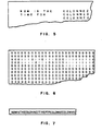
- FIGS. 5, 6 and 7 The spatial correspondence of the coded representations of the alphanumeric characters of the memory with the true alphanumeric characters displayed on the CRT tube, is represented in FIGS. 5, 6 and 7 in the case where the alphanumeric information displayed is arranged by column.
- the position information stored in the matrix memory represented in FIG. 6 corresponds directly to the arrangement in columns of the alphanumeric data of FIG. 5. Consequently, the position bits "1" are extracted from the matrix memory, FIG. 6 , in synchronization with the scanning of the CRT display tube of FIG. 5. There is therefore access in the sequential access memory of FIG.
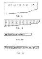
- Figures 8-11 show how the system of the present invention processes character attributes such as underlining a character or shifting a character up or down relative to the character line.
- the alphanumeric data displayed shows that the two letters "is” are underlined and that the number "2" is raised to the power "N".
- the information concerning the attributes of character is stored only in association with the coded data to which there is sequential access, figure 10.
- a code underscore (CDS) is stored before the two letters "is”
- an underscore (CFS) code is stored after the two letters "is”.
- the reverse half-line code (RHI) is used before “N” and a half-line code (HI) is used after the "N” to return to the character line .
- the coded data representing the various character attributes such as the CDS codes , CFS, RHI, or HI, are stored similarly by being associated with the coded representations of the characters then displayed.
- the system of the present invention operates so as to apply to the CRT tube signals which represent the entire character to be displayed, and its refreshing to a particular display position before the scanning means are moved to the next display position.
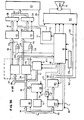
- the basic control logic is shown in Figures 35 and 36.
- the system is controlled by a conventional microprocessor 12 which provides the required data which will be described below.
- the control signals for the main deflection of the beam of the CRT tube 13 control the deflection coils of axes X and Y of the CRT tube.
- the logic shown in Figures 35 and 36 allows the scanning electron beam of the CRT tube to move from left to right, as shown schematically in Figure 31.
- each line 14 of the main deflection path cor responds to a line containing several character positions and forming part of an entire page displayed.
- signals whose frequency is higher are applied to a micro-deflection means so as to generate a micro-frame, or sub-frame, under the control of the signals supplied by the logic of Figures 35 and 36.
- This micro-frame scanning which provides the particular character is shown in Figure 32 and produces the displayed character "N".
- the character "N" is produced by the video signal which is controlled from a character generator which operates in synchronization with the micro-frame to produce the character.
- a character such as that shown in FIG. 32, is completely generated before the scanning of the main deflection line 14 moves to the next character position.
- the alphanumeric data to be displayed on the CRT cathode ray tube 13 are stored in a selective access memory (RAM) 16 in the microprocessor 12 which controls the word processing system.
- the RAM memory 16 contains the coded representations of the data of a block, or page, of alphanumeric characters to be displayed on the CRT tube 13 according to a sequence of storage positions spatially corresponding to the positions of the characters of the page or block to display on the CRT tube.
- the RAM 16 also contains control codes which determine the position of the characters as well as the characteristics of the displayed characters, for example, a character underline.
- the address counter 19 under the control of the input control logic 24, controls the sequences of the character data coming from the RAM memory 16 so that a sequence of character data is sent to the character generator, which will be described below, in a sequence corresponding spatially to the display of the CRT tube 13.
- the purpose of the address selector 17, FIG. 35 is to multiplex the position signals coming from the counter addresses 19 with all the other addresses then sent to the RAM memory 16 along the bus 18 of the microprocessor or with other functions independent of the microprocessor.
- the data selection means 20 performs a similar multiplexing function with regard to the data extracted from the RAM memory of the microprocessor, that is to say, the data relating to other functions independent of the microprocessor.
- the data is sent by the data bus 21 while the data bit which indicates the character to be displayed at the position indicated by the counter 19 on the CRT tube 13, is sent along the bus 22 to the input register 23 while that the address counter 19 is incremented by "one".
- the input control logic 24 which operates under the control of a high frequency (60 nanosecond) clock 25 examines the byte of data of register 23, via bus 27, to determine if the byte is a code instruction, command code or character code.
- an instruction code could be: "LOAD THE FOLLOWING TWO MULTIPLETS IN THE ADDRESS COUNTER 19".
- the control logic 24 transmits the following two bytes in the counter 19, via the buses 37 and 38.
- this byte passes , via bus 29, to the RAM buffer 28.
- a character code follows a command code.
- the sixteen byte RAM buffer memory 28 is of particularly advantageous use in display systems where the spacing allocated to the character is variable, depending on the width of the character. For example, the "W" can occupy a space that is almost twice the space occupied by an "I". Thus, is it conceivable, for a particular sweep over a whole line of the CRT tube, that a line having many narrow characters could contain a number of characters exceeding by up to 20% the number of characters that a line having larger characters.
- the sixteen byte buffer memory 28 serves for the storage of command and character codes which can then be sent to the character generating means of the system of the present invention in synchronization with the main deflection on the scan line 14 of the figure 31.
- the buffer memory 28 operates under the control of the counter 30 which serves as an input pointer to the positions of the memory 28, through the gate 31, and of the counter 32 which serves as an output pointer to the positions of the buffer memory 28, by door 31.
- the input and output counters 30 and 32 are controlled by the control logic 24, on the one hand by the clock 33 and erase 34 lines in the direction of the counter 30, and on the other hand by the clock 35 and erase 36 lines towards the counter 32.
- the device When the buffer is loaded, the device is located at the stage from which the alphanumeric character to be displayed on a given display line can be refreshed in synchronization with the scanning means of the CRT tube.
- the video signal is controlled by the generator of characters in synchronization with a sweep that involves a horizontal sweep of main deflection along lines 14 in Figure 31 as well as a vertical sweep by micro-frame, as shown in Figure 32.
- the beam runs horizontally along line 14, it is subjected to a vertical sub-frame along line 39, as shown in detail in FIG. 32.
- each character area 40, 40 'or 40 corresponds to a width of five exhausts, and the vertical scan 39 is divided into eight scan lines.
- the character generator by selectively activating the required combination of video line units 41, allows the alphanumeric character to be displayed and cyclically refreshed.
- the letter "N” appears in the character area 40 while the character area 40 'remains “blank A ", that is to say that there is no line unit active video, and the 40 "character area contains a portion of the alphanu character meric "F".
- the address applied to memories 47 and 48 includes eleven bits applied by buses 54 and 49. These eleven bits contain the eight bits coming from the character register 46 sent on the bus 50, and the three bits coming from the address counter 51 sent along the bus 52.
- the first two scan lines of the selected character configuration are sent from memories 47 and 48 respectively, by buses 55 and 56, to the scan registers 42 and 43 which have been conditioned for a loading operation by a signal coming from the output control logic, by the line 57.
- the scan line register 42 stores the data indicating the configuration by points or by video units of the first scan line of the pair, while the scan register 43 proceeds in the same way for the second line of the pair.
- the pulse generator 75 under the control of the output control logic 53, provides a send pulse either to gate 58 associated with scan register 43 or to gate 59 associated with scan register 42.
- the pulse generator conditions gate 58, for example, every 15 nanoseconds so that it lets the data coming from the scanning line register 43 pass along the bus 60 or else it conditions the gate 59 so that it lets the data coming from the scanning line register 42 pass along the bus 61.
- the output control logic 53 increments the address counter 51 by means of an appropriate signal on line 66 in order to change the three-bit input coming from the address counter 51, by the bus 52, which has the effect of allowing the memories 47 and 48 of the character generator to respectively supply the following two scanning lines of the character area then scanned.
- the control logic of FIGS. 35 and 36 is provided with means for spatially placing the characters stored in a memory, such as that shown in FIG. 4, in which the information concerning the spatial position is stored sequentially with the corresponding characters.
- a spacing operation which is indicated by a spacing code, namely the spc code (0-255); the value in parentheses indicating the number of spaces.
- the first entry coming from the RAM memory 16 in the direction of the entry register 28 is then the command code indicating a spacing operation.
- the control logic 24 which examined the data present in the register 23, by the bus 27, determines that we are dealing with a spacing control code.
- the next data byte that indicates the number 150 goes into the buffer 28 with the space control code, and is not loaded into the register of characters 46, but, on the other hand, passes into the space counter 69 which has been conditioned, through the door 71 and the line 70, by the space control code present in the control register 147.
- the counter 69 is then decremented by the 480 nanosecond clock, 72 (which corresponds to the exhaust speed). As long as there is an account in the counter 69, a signal is applied, via line 73, to the output control logic 53 which, in turn, inhibits the pulse generator 75.
- FIGS. 33 and 35 embodiment in which the organization of the memory providing the sequential access storage means of the coded representations of the displayed characters is shared into two memory units, namely, a matrix memory unit which stores only the data representing the positions of the displayed characters, as shown in FIG. 2, unit in which the bit positions "1" correspond spatially to the positions of the alphanumeric characters respective displayed on the CRT tube, and a second memory unit, as shown in FIG. 3, in which the coded representations of the displayed characters are stored in the same sequence as that of the locations of the position information in FIG. 2 and , consequently, following the same sequence as that of the scanning of the characters on the display tube.
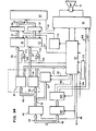
- Figures 33 and 34 show a modification of the control logic of Figures 35 and 36 to spatially place the displayed characters using the two storage means which operate together in place of a single storage means. Since most functions of the control logic of Figures 33 and 34 are identical to those described previously with reference to Figures 35 and 36, Figures 33 and 34 using the same reference numerals to designate the functional units which remain unchanged, the operation of these units will not be described again. The following description will mainly relate to the additional or modified functional units.
- a portion 116 of the RAM memory 16 contains a matrix of positions of the type illustrated in FIG. 2.
- Another portion 116 ′ of the RAM memory 16 contains character code data, as shown in FIG. 3 , in sequential order, without any position information.
- the input control logic 24 has the possibility of conditioning the address counter 19, via the line 101, to address the memory section 116 ′, therefore, to load the 16-bit buffer memory 28 of a sequence control code and character code data, as previously described. This data is ready to be applied to the character generator and then to the scan line register 42 and 43 under the control of the output control logic 53, as described previously with reference to FIG. 36.
- the position at which each sequential character must be displayed is determined by the input control logic 24 which conditions the address counter 119, by the conditioning line 100, of so that it addresses the matrix memory unit 116.
- the input control logic 24 sends the position data output from the matrix unit 116, through the input register 23, to the register of position 102.
- the combination of the position register 102 and the clock 103 processes the spatial data from the memory unit 116 in the same way as the combination of the counter 69 and the clock 72 of Figures 35 and 36, when it processes the spatial data stored with the command code and character data of the system.
- the command code is the start code for underlining CDS, as has been mentioned. beforehand for the letter "i” in FIG. 11.
- This code from register 47 is loaded into the display control register 105.
- this control code is in the display control register 105, during the display of the characters "i" and "s" (FIG.
- control register 105 supplies a signal on line 108, to the output control logic 53 which supplies the underline signals, by lines 109 and 110 , at the respective doors 111 and 112 so that these pass an underline signal through the lines 113 and 114, to the registers 42 and 43, as well as the scanning line configurations applied to these registers, by the buses 55 and 56
- command register 105 ends the underline with line 106.
- the command register 105 controls the electronic circuits 64 of the CRT display tube, using signals on the lines. 106 and 107 in order to subject the displayed character to a half-spacing upwards and to a half-spacing downwards.
- FIG. 12 shows a portion of the CRT tube on which is displayed a page portion carrying alphanumeric data with proportional spacing.
- "Proportally spaced data” means data that is uniformly spaced regardless of the width of the characters.
- the character areas that is to say, the width of the escape reserved for the particular character at the particular display position, must have a variable width.
- the character zones at each display position corresponded to five escape units each corresponding to a time of 480 nanoseconds. With proportional spacing, the width of the character zones can be any, ranging from three to seven of these 480 nanosecond escape units.
- each spacing can be represented by a string of five "0" representing five escape units
- the character area reserved for narrow characters can include three escape units, i.e., two bits “1 "followed by a bit” 0 "- as shown in figure 13 at 115, position which represents the narrow character” I “of the display of figure 12, or else four bits” 1 "followed by a bit” 0 " -as shown in Figure 13 at 117, position which represents the character “S” of the display of Figure 12.
- the character "W” would be represented by seven exhaust units, namely, six " 1 "and the bit "zero", this last bit used to delimit the characters between them.
- the display control logic described previously with reference to FIGS. 33 and 34 operates in the manner described except, of course, that the character signal on line 104 in coming from the position register 102 to pass to the output control logic 53, simply signals that a portion of a character must be displayed at this escape position.
- a character having a character zone of six escape positions a chain of five "1" is applied to the control logic 53, by the signal line 104, while a narrow character occupying only three escape positions corresponds to a chain of two "1" applied by line 104 to the control logic 53.
- the generator d the pulses are actuated to supply the previously described signals which condition the gates 58 and 59 to transmit the scanning line configurations from the scanning line registers 43 and 42.
- the character generator i.e., ROS memories 47 and 48
- the character generator provides the character configuration on a smaller number of scan lines for a narrow character, and on a larger number e of scan lines for a wide character.
- the space counter 69 simply counts the number of escape positions separating the last displayed character of the next character to be displayed, point at which a signal is sent on line 73 to the output control logic 53 so as to activate the generator 75 and allow the character defined in the ROS memories 47 and 48 of the character generator , to be displayed according to a selected number of scan lines depending, of course, on the width of the character.
- FIG. 15 shows a display CR T in which an alphanumeric data block is displayed on two columns.
- the cursor of FIG. 15 is indicated by the dash 81.
- the organization of the memory comprises two units which operate simultaneously, each being represented in FIGS. 16 and 17.
- the matrix memory of FIG. 16 shows the position of the alphanumeric characters displayed in Figure 15 while Figure 17 shows the sequential access memory which contains the characters in sequence.
- this cursor has its position designated by a bit "1" in the matrix memory, figure 16, and is stored as a discrete character in the sequential access memory of figure 17.
- FIG. 18 schematically represents the organization of the single memory which alone fulfills the functions of the storage means of FIGS. 16 and 17.
- FIGS. 15 to 17, 19 to 21, 23 to 25 and 27 to 29 illustrate the procedure which uses the memory organization represented in FIGS. 16 and 17 where the character data and the character code data are stored in a separate sequential storage means, FIG. 17, and where the position and position information 'space is stored in a matrix storage means ( Figure 16).
- Figure 16 the position and position information 'space is stored in a matrix storage means
- the logic of the microprocessor can now treat the contour of the defined segment in the same way as are the margins of a page during the operations of delivery in text format such as justification, adjustment, keyboard entry of columns, column offset, and definition of column margins.
- the microprocessor also inserts the representations 84 'and 184' of the respective hooks of "displacement towards initial" and of “displacement towards final” in the sequential storage means, FIG. 25, in the sequential positions which must be occupied by the representation of these hooks of "displacement towards”.
- the first character of the column to be moved, "B" 83 is moved by first moving the cursor 81 of figure 23 to a position placed under the character "B" 83 and by entering a keyboard command "move from”. Following this keyboard entry, the microprocessor inserts a pointer "from” to the representation 83 'of the character "B" in the sequential memory shown in Figure 25.
Landscapes
- Engineering & Computer Science (AREA)
- Theoretical Computer Science (AREA)
- Physics & Mathematics (AREA)
- General Physics & Mathematics (AREA)
- Computer Hardware Design (AREA)
- Computational Linguistics (AREA)
- Artificial Intelligence (AREA)
- Audiology, Speech & Language Pathology (AREA)
- Health & Medical Sciences (AREA)
- General Health & Medical Sciences (AREA)
- General Engineering & Computer Science (AREA)
- Radar, Positioning & Navigation (AREA)
- Remote Sensing (AREA)
- Controls And Circuits For Display Device (AREA)
- Document Processing Apparatus (AREA)
- Digital Computer Display Output (AREA)
Applications Claiming Priority (2)
| Application Number | Priority Date | Filing Date | Title |
|---|---|---|---|
| US46894 | 1979-06-08 | ||
| US06/046,894 US4240075A (en) | 1979-06-08 | 1979-06-08 | Text processing and display system with means for rearranging the spatial format of a selectable section of displayed data |
Publications (2)
| Publication Number | Publication Date |
|---|---|
| EP0020932A1 true EP0020932A1 (de) | 1981-01-07 |
| EP0020932B1 EP0020932B1 (de) | 1986-09-17 |
Family
ID=21945969
Family Applications (1)
| Application Number | Title | Priority Date | Filing Date |
|---|---|---|---|
| EP80102238A Expired EP0020932B1 (de) | 1979-06-08 | 1980-04-25 | System zur Verarbeitung und Anzeige von Texten |
Country Status (4)
| Country | Link |
|---|---|
| US (1) | US4240075A (de) |
| EP (1) | EP0020932B1 (de) |
| JP (1) | JPS55164934A (de) |
| DE (1) | DE3071759D1 (de) |
Cited By (5)
| Publication number | Priority date | Publication date | Assignee | Title |
|---|---|---|---|---|
| EP0054693A3 (en) * | 1980-12-24 | 1984-09-19 | International Business Machines Corporation | Word processing system with full page representation display |
| EP0066139A3 (en) * | 1981-05-29 | 1986-03-26 | International Business Machines Corporation | Text processing system with displaying of formatted pages |
| EP0190511A1 (de) * | 1984-12-29 | 1986-08-13 | Canon Kabushiki Kaisha | Blockverarbeitungsanlage |
| US4686649A (en) * | 1981-05-29 | 1987-08-11 | International Business Machines Corporation | Word processor with alternative formatted and unformatted display modes |
| FR2657988A1 (fr) * | 1990-02-06 | 1991-08-09 | Sextant Avionique | Procede et dispositif d'affichage sur ecran a matrice de points. |
Families Citing this family (32)
| Publication number | Priority date | Publication date | Assignee | Title |
|---|---|---|---|---|
| US4445186A (en) * | 1978-04-14 | 1984-04-24 | Eg&G, Inc. | Underwater mapping apparatus and method |
| AU530568B2 (en) * | 1980-10-31 | 1983-07-21 | Canon Kabushiki Kaisha | Serial printing apparatus with memory and display |
| JPS57101887A (en) * | 1980-12-16 | 1982-06-24 | Sony Corp | Character display |
| US4435777A (en) * | 1981-05-18 | 1984-03-06 | International Business Machines Corporation | Interactively rearranging spatially related data |
| US4435778C1 (en) * | 1981-05-18 | 2002-09-03 | Ibm | Method for editing spatially related data in an interactive text processing system |
| US4507753A (en) * | 1981-05-18 | 1985-03-26 | International Business Machines Corporation | Method for automatic field width expansion in a text processing system during interactive entry of displayed record selection criterium |
| US4437093A (en) | 1981-08-12 | 1984-03-13 | International Business Machines Corporation | Apparatus and method for scrolling text and graphic data in selected portions of a graphic display |
| CA1204215A (en) * | 1981-09-01 | 1986-05-06 | Hiroyuki Ueda | Electronic equipment having a character sequence memory and a character display |
| US4445795A (en) * | 1981-09-24 | 1984-05-01 | International Business Machines | Method and apparatus for merge processing in a text processing system |
| JPS5856138A (ja) * | 1981-09-24 | 1983-04-02 | インタ−ナショナル ビジネス マシ−ンズ コ−ポレ−ション | 複数のテキスト・カラムのフオ−マツト化方法 |
| JPH0782551B2 (ja) * | 1982-01-30 | 1995-09-06 | キヤノン株式会社 | 文字処理装置 |
| US4546451A (en) * | 1982-02-12 | 1985-10-08 | Metheus Corporation | Raster graphics display refresh memory architecture offering rapid access speed |
| JPS58144890A (ja) * | 1982-02-23 | 1983-08-29 | ミノルタ株式会社 | 文字発生装置における文字表示領域制御方式 |
| US4434420A (en) | 1982-06-21 | 1984-02-28 | Motorola, Inc. | Interline spacing adjustment circuit in a scanning CRT visual display system |
| JPS5968040A (ja) * | 1982-10-11 | 1984-04-17 | Fujitsu Ltd | カード様式変更処理方法 |
| GB2143066B (en) * | 1983-06-14 | 1987-02-18 | Canon Kk | Memory control unit |
| US4625203A (en) * | 1983-10-18 | 1986-11-25 | Digital Equipment Corporation | Arrangement for providing data signals for a data display system |
| CA1243138A (en) * | 1984-03-09 | 1988-10-11 | Masahiro Kodama | High speed memory access circuit of crt display unit |
| US4675833A (en) * | 1984-04-13 | 1987-06-23 | Xyvision, Inc. | Processor controlled photocomposition system |
| US5089990A (en) * | 1984-08-14 | 1992-02-18 | Sharp Kabushiki Kaisha | Word processor with column layout function |
| USRE36653E (en) * | 1984-09-06 | 2000-04-11 | Heckel; Paul C. | Search/retrieval system |
| US5289569A (en) * | 1985-05-21 | 1994-02-22 | Canon Kabushiki Kaisha | Document processing system capable of simultaneously displaying two continuous document pages in accordance with a selected binding position |
| JPS6244877A (ja) * | 1985-08-22 | 1987-02-26 | Toshiba Corp | 機械翻訳装置 |
| US4903233A (en) * | 1986-06-20 | 1990-02-20 | Sharp Kabushiki Kaisha | Word processor having capability of continuously entering documents into a column or a block of an editing system |
| US4913566A (en) * | 1987-01-07 | 1990-04-03 | Brother Kobyo Kabushiki Kaisha | Spell check device with display |
| US4882683B1 (en) * | 1987-03-16 | 1995-11-07 | Fairchild Semiconductor | Cellular addrssing permutation bit map raster graphics architecture |
| US5186551A (en) * | 1987-10-15 | 1993-02-16 | Brother Kogyo Kabushiki Kaisha | Printing apparatus for printing randomly input data in order |
| EP0449322B1 (de) * | 1990-03-29 | 1999-07-28 | Canon Kabushiki Kaisha | Textverarbeitungsvorrichtung mit Textformatierung |
| US5724067A (en) * | 1995-08-08 | 1998-03-03 | Gilbarco, Inc. | System for processing individual pixels to produce proportionately spaced characters and method of operation |
| US5592175A (en) * | 1995-08-25 | 1997-01-07 | Motorola, Inc. | Location determination method and apparatus for a communication unit |
| DE69916398T2 (de) * | 1998-11-09 | 2004-09-02 | Fujitsu Ltd., Kawasaki | Elektronische Transaktionsvorrichtung |
| JP3910204B2 (ja) * | 2005-07-04 | 2007-04-25 | 三菱電機株式会社 | 画像発生装置及び画像表示装置並びに画像発生方法及び画像表示方法 |
Citations (6)
| Publication number | Priority date | Publication date | Assignee | Title |
|---|---|---|---|---|
| US3582946A (en) * | 1967-09-28 | 1971-06-01 | Nippon Electric Co | Cathode-ray tube display device |
| FR2131614A5 (de) * | 1971-03-26 | 1972-11-10 | Licentia Gmbh | |
| FR2331841A1 (fr) * | 1975-11-11 | 1977-06-10 | Sperry Rand Corp | Systeme d'affichage de trame du type numerique |
| FR2333319A1 (fr) * | 1975-11-28 | 1977-06-24 | Ibm | Memoire tampon de regeneration |
| US4074254A (en) * | 1976-07-22 | 1978-02-14 | International Business Machines Corporation | Xy addressable and updateable compressed video refresh buffer for digital tv display |
| DE2845290A1 (de) * | 1977-11-16 | 1979-05-17 | Ibm | Datensichtgeraet |
Family Cites Families (17)
| Publication number | Priority date | Publication date | Assignee | Title |
|---|---|---|---|---|
| US3540012A (en) * | 1967-12-26 | 1970-11-10 | Sperry Rand Corp | Crt display editing circuit |
| US3618032A (en) * | 1968-12-09 | 1971-11-02 | Ibm | Automatic data composing, editing and formatting system |
| US3603966A (en) * | 1969-02-14 | 1971-09-07 | Bunker Ramo | Data display system |
| US3648245A (en) * | 1970-01-30 | 1972-03-07 | Burroughs Corp | Time-shared apparatus for operating plural display media, and display methods including paging, displaying special forms and displaying information in tabulated form |
| US3675208A (en) * | 1970-05-28 | 1972-07-04 | Delta Data Syst | Editing system for video display terminal |
| US3740743A (en) * | 1971-03-29 | 1973-06-19 | Columbia Broadcasting Sys Inc | Character generating apparatus for television titling |
| US3729730A (en) * | 1971-04-14 | 1973-04-24 | Cogar Corp | Display system |
| US3729714A (en) * | 1971-06-23 | 1973-04-24 | Ibm | Proportional space character display including uniform character expansion |
| US3786429A (en) * | 1971-07-12 | 1974-01-15 | Lexitron Corp | Electronic text display system which simulates a typewriter |
| US3792462A (en) * | 1971-09-08 | 1974-02-12 | Bunker Ramo | Method and apparatus for controlling a multi-mode segmented display |
| US4121228A (en) * | 1975-09-15 | 1978-10-17 | Cowe Alan B | Photocomposition machine with keyboard entry and CRT display |
| US4054948A (en) * | 1975-10-14 | 1977-10-18 | Realty & Industrial Corporation | Proportional spacing and electronic typographic apparatus |
| US4070710A (en) * | 1976-01-19 | 1978-01-24 | Nugraphics, Inc. | Raster scan display apparatus for dynamically viewing image elements stored in a random access memory array |
| US4149145A (en) * | 1977-02-17 | 1979-04-10 | Xerox Corporation | Fax processor |
| US4146879A (en) * | 1977-04-12 | 1979-03-27 | International Business Machines Corporation | Visual display with column separators |
| US4158837A (en) * | 1977-05-17 | 1979-06-19 | International Business Machines Corporation | Information display apparatus |
| GB1533499A (en) * | 1977-07-07 | 1978-11-29 | Ibm | Text processing apparatus |
-
1979
- 1979-06-08 US US06/046,894 patent/US4240075A/en not_active Expired - Lifetime
-
1980
- 1980-03-18 JP JP3349180A patent/JPS55164934A/ja active Granted
- 1980-04-25 EP EP80102238A patent/EP0020932B1/de not_active Expired
- 1980-04-25 DE DE8080102238T patent/DE3071759D1/de not_active Expired
Patent Citations (7)
| Publication number | Priority date | Publication date | Assignee | Title |
|---|---|---|---|---|
| US3582946A (en) * | 1967-09-28 | 1971-06-01 | Nippon Electric Co | Cathode-ray tube display device |
| FR2131614A5 (de) * | 1971-03-26 | 1972-11-10 | Licentia Gmbh | |
| FR2331841A1 (fr) * | 1975-11-11 | 1977-06-10 | Sperry Rand Corp | Systeme d'affichage de trame du type numerique |
| FR2333319A1 (fr) * | 1975-11-28 | 1977-06-24 | Ibm | Memoire tampon de regeneration |
| US4074254A (en) * | 1976-07-22 | 1978-02-14 | International Business Machines Corporation | Xy addressable and updateable compressed video refresh buffer for digital tv display |
| DE2845290A1 (de) * | 1977-11-16 | 1979-05-17 | Ibm | Datensichtgeraet |
| FR2409558A1 (fr) * | 1977-11-16 | 1979-06-15 | Ibm | Systeme d'affichage de caracteres |
Non-Patent Citations (1)
| Title |
|---|
| IBM TECHNICAL DISCLOSURE BULLETIN, Vol. 17, No. 3, Aout 1974 New York (US) SCHOMBURG et al.: "Raster display with Half-index", pages 682-683 * En entier * * |
Cited By (6)
| Publication number | Priority date | Publication date | Assignee | Title |
|---|---|---|---|---|
| EP0054693A3 (en) * | 1980-12-24 | 1984-09-19 | International Business Machines Corporation | Word processing system with full page representation display |
| EP0066139A3 (en) * | 1981-05-29 | 1986-03-26 | International Business Machines Corporation | Text processing system with displaying of formatted pages |
| US4686649A (en) * | 1981-05-29 | 1987-08-11 | International Business Machines Corporation | Word processor with alternative formatted and unformatted display modes |
| EP0190511A1 (de) * | 1984-12-29 | 1986-08-13 | Canon Kabushiki Kaisha | Blockverarbeitungsanlage |
| FR2657988A1 (fr) * | 1990-02-06 | 1991-08-09 | Sextant Avionique | Procede et dispositif d'affichage sur ecran a matrice de points. |
| EP0447274A1 (de) * | 1990-02-06 | 1991-09-18 | Sextant Avionique | Verfahren und Einrichtung für Bildpunktmatrixanzeige |
Also Published As
| Publication number | Publication date |
|---|---|
| JPS6221127B2 (de) | 1987-05-11 |
| DE3071759D1 (en) | 1986-10-23 |
| JPS55164934A (en) | 1980-12-23 |
| US4240075A (en) | 1980-12-16 |
| EP0020932B1 (de) | 1986-09-17 |
Similar Documents
| Publication | Publication Date | Title |
|---|---|---|
| EP0020932B1 (de) | System zur Verarbeitung und Anzeige von Texten | |
| US6678410B1 (en) | Generating a glyph | |
| US4428065A (en) | Data processing system with multiple display apparatus | |
| FR2691819A1 (fr) | Appareil et procédé de génération d'implantations textuelles de lignes. | |
| FR2483655A1 (fr) | Appareil de traitement de documents pour editer et imprimer des documents d'informations | |
| JP2002533855A (ja) | 表示部材からの文章の読み取りをサポートするための装置 | |
| US4511267A (en) | Method for changing the supply of characters in an ideographic typewriter by combining and storing individual characters | |
| FR2571869A1 (fr) | Dispositif pour editer des documents en couleurs. | |
| US4189727A (en) | Display advance system for a word processor | |
| EP0020985A2 (de) | Textbearbeitungssystem mit einer Kathodenstrahlanzeige | |
| US5970225A (en) | Display of selected printer response for distinct applications | |
| GB2246102A (en) | Computerised page layout composition | |
| JPS59173835A (ja) | 字形選択装置 | |
| EP0020927B1 (de) | Anzeigesystem mit Haupt- und Unterrasterabtastung | |
| JP3115059B2 (ja) | 構造化文書編集方法 | |
| JPS5816189B2 (ja) | 文字パタ−ン発生方式 | |
| Bratley et al. | Information processing in dictionary making: Some technical guidelines | |
| JPS608921A (ja) | 文字処理装置 | |
| JPH0346857B2 (de) | ||
| JP2626769B2 (ja) | 出力制御装置及び方法 | |
| EP0105491A2 (de) | Zeichensatzanzeige- und Textaufbereitungssystem | |
| JPS58139243A (ja) | 文字デ−タ処理装置 | |
| JP2612402B2 (ja) | 表示制御方法 | |
| FR2528208A1 (en) | Text character display controlling circuit - has character memory forming compressed words representing character matrix | |
| EP0085593A1 (de) | Gerät zum Schreiben und Lesen in einem Seitenspeicher eines Kathodenstrahlröhren-Anzeigegeräts |
Legal Events
| Date | Code | Title | Description |
|---|---|---|---|
| PUAI | Public reference made under article 153(3) epc to a published international application that has entered the european phase |
Free format text: ORIGINAL CODE: 0009012 |
|
| AK | Designated contracting states |
Designated state(s): DE FR GB |
|
| 17P | Request for examination filed |
Effective date: 19810416 |
|
| GRAA | (expected) grant |
Free format text: ORIGINAL CODE: 0009210 |
|
| AK | Designated contracting states |
Kind code of ref document: B1 Designated state(s): DE FR GB |
|
| REF | Corresponds to: |
Ref document number: 3071759 Country of ref document: DE Date of ref document: 19861023 |
|
| PLBE | No opposition filed within time limit |
Free format text: ORIGINAL CODE: 0009261 |
|
| STAA | Information on the status of an ep patent application or granted ep patent |
Free format text: STATUS: NO OPPOSITION FILED WITHIN TIME LIMIT |
|
| 26N | No opposition filed | ||
| PGFP | Annual fee paid to national office [announced via postgrant information from national office to epo] |
Ref country code: FR Payment date: 19900328 Year of fee payment: 11 |
|
| PGFP | Annual fee paid to national office [announced via postgrant information from national office to epo] |
Ref country code: GB Payment date: 19900331 Year of fee payment: 11 |
|
| PGFP | Annual fee paid to national office [announced via postgrant information from national office to epo] |
Ref country code: DE Payment date: 19900427 Year of fee payment: 11 |
|
| PG25 | Lapsed in a contracting state [announced via postgrant information from national office to epo] |
Ref country code: GB Effective date: 19910425 |
|
| PG25 | Lapsed in a contracting state [announced via postgrant information from national office to epo] |
Ref country code: FR Effective date: 19911230 |
|
| GBPC | Gb: european patent ceased through non-payment of renewal fee | ||
| PG25 | Lapsed in a contracting state [announced via postgrant information from national office to epo] |
Ref country code: DE Effective date: 19920201 |
|
| REG | Reference to a national code |
Ref country code: FR Ref legal event code: ST |