EP0020977B1 - Druckerwagen für Typenraddruckwerk - Google Patents
Druckerwagen für Typenraddruckwerk Download PDFInfo
- Publication number
- EP0020977B1 EP0020977B1 EP80102569A EP80102569A EP0020977B1 EP 0020977 B1 EP0020977 B1 EP 0020977B1 EP 80102569 A EP80102569 A EP 80102569A EP 80102569 A EP80102569 A EP 80102569A EP 0020977 B1 EP0020977 B1 EP 0020977B1
- Authority
- EP
- European Patent Office
- Prior art keywords
- carrier
- rails
- printer
- set forth
- platen
- Prior art date
- Legal status (The legal status is an assumption and is not a legal conclusion. Google has not performed a legal analysis and makes no representation as to the accuracy of the status listed.)
- Expired
Links
- 241000723353 Chrysanthemum Species 0.000 claims description 2
- 235000005633 Chrysanthemum balsamita Nutrition 0.000 claims description 2
- 239000000463 material Substances 0.000 description 2
- BASFCYQUMIYNBI-UHFFFAOYSA-N platinum Chemical compound [Pt] BASFCYQUMIYNBI-UHFFFAOYSA-N 0.000 description 2
- OKTJSMMVPCPJKN-UHFFFAOYSA-N Carbon Chemical compound [C] OKTJSMMVPCPJKN-UHFFFAOYSA-N 0.000 description 1
- 229910052799 carbon Inorganic materials 0.000 description 1
- 230000004048 modification Effects 0.000 description 1
- 238000012986 modification Methods 0.000 description 1
- 229910052697 platinum Inorganic materials 0.000 description 1
Images


Classifications
-
- B—PERFORMING OPERATIONS; TRANSPORTING
- B41—PRINTING; LINING MACHINES; TYPEWRITERS; STAMPS
- B41J—TYPEWRITERS; SELECTIVE PRINTING MECHANISMS, i.e. MECHANISMS PRINTING OTHERWISE THAN FROM A FORME; CORRECTION OF TYPOGRAPHICAL ERRORS
- B41J1/00—Typewriters or selective printing mechanisms characterised by the mounting, arrangement or disposition of the types or dies
- B41J1/22—Typewriters or selective printing mechanisms characterised by the mounting, arrangement or disposition of the types or dies with types or dies mounted on carriers rotatable for selection
- B41J1/24—Typewriters or selective printing mechanisms characterised by the mounting, arrangement or disposition of the types or dies with types or dies mounted on carriers rotatable for selection the plane of the type or die face being perpendicular to the axis of rotation
-
- B—PERFORMING OPERATIONS; TRANSPORTING
- B41—PRINTING; LINING MACHINES; TYPEWRITERS; STAMPS
- B41J—TYPEWRITERS; SELECTIVE PRINTING MECHANISMS, i.e. MECHANISMS PRINTING OTHERWISE THAN FROM A FORME; CORRECTION OF TYPOGRAPHICAL ERRORS
- B41J19/00—Character- or line-spacing mechanisms
- B41J19/18—Character-spacing or back-spacing mechanisms; Carriage return or release devices therefor
- B41J19/20—Positive-feed character-spacing mechanisms
-
- B—PERFORMING OPERATIONS; TRANSPORTING
- B41—PRINTING; LINING MACHINES; TYPEWRITERS; STAMPS
- B41J—TYPEWRITERS; SELECTIVE PRINTING MECHANISMS, i.e. MECHANISMS PRINTING OTHERWISE THAN FROM A FORME; CORRECTION OF TYPOGRAPHICAL ERRORS
- B41J29/00—Details of, or accessories for, typewriters or selective printing mechanisms not otherwise provided for
- B41J29/02—Framework
Definitions
- the present invention relates to printer carts with a single printing element and more particularly, the printer carriage of printers in the form of a daisy on which are mounted both a selection motor and a carriage carrying the element. print and ribbon cartridges.
- printers with a single printing element are currently commercially available. The most common are ball or print wheel type.
- IBM 72 series and IBM magnetic card printing systems are conventional ball printers.
- the printers of these two systems include a carriage carrying a printing element which can be tilted and rotated for printing.
- the fundamental difference between the trolleys of the two systems indicated above lies in the fact that in the first system, the exhaust is controlled by rack and pinion while in the second system, the exhaust is controlled by ratchet and screw unending.
- the IBM 6240 magnetic card printing system is a classic example of a feeder printer in the shape of a feeder. It includes a carriage on which are mounted a selection motor and a ribbon cartridge.
- the selection engine has a hub to which a daisy-shaped printing element is connected. This printing element can be rotated to select characters during printing.
- a print wheel printer is also presented in US Pat. No. 4,124,312.
- This reference presents a carriage carrying a daisy-shaped printing element housed in a cartridge, a ribbon cartridge and a selection motor.
- it does not have an engine carriage, which in turn carries a carriage on which the printing element and the ribbon cartridges are mounted, said motor carriage being able to be easily adjusted to adjust both the motor and the cartridge. of the printing element in order to obtain a good printing quality and to ensure proper handling of the paper.
- a printer carriage with a daisy-shaped print wheel carrying a selection motor and a carriage on which the printing element and the ribbon cartridges are mounted will be described here.
- the printer carriage comprises adjustment means in the form of eccentric rails which can be adjusted in rotation.
- the motor and the carriage carrying the cartridges are mounted independently on the rails, horizontally movable along these and biased by spring against said rails.
- the rotation of the rails causes the vertical movement of the cartridge holder carriage and of the motor and their passage in a side-by-side and vertical position relative to the platen of the printer.
- the printer carriage also has a structure which can have an adjustment means ensuring the horizontal movement of the cartridge carriage along the rails to and from the stage, receiving exhaust rails included in the printer and along which escapes the printer carriage during printing, and includes a follower associated with a worm to control the printer carriage escapement.
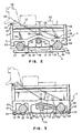
- the main components of the printer carriage produced according to the teachings of the present invention are the chassis 1, a left adjustable eccentric rail 2, a right adjustable eccentric rail 3 and a base 4.
- the chassis 1 is preferably a single piece molded in a rigid material.
- the chassis 1 is composed of a bottom 5, of ribs 6, 7 and 8 and uprights 9 and 10 perpendicular to the bottom 5.
- Channels 11 and 12 are molded in the underside of the bottom 5 and receive the exhaust rails 13 and 14 ( Figure 2) along which escapes the chassis 1 during the rotation of an endless screw 15.
- the exhaust rails 13 and 14 are mounted between the sides of the chassis of a printer (not shown), parallel to the plate 89 (FIG. 4) of a printer.
- the frame 1 escapes between the sides of the printer frame during printing on a recording medium (not shown) arranged on the platen.
- V-shaped cutouts 16 and 17 are provided in the upper parts of the uprights 9 and 10, respectively, to receive eccentric extensions 18 and 19 of the rails 2 and 3, respectively. Openings 20 and 21 are provided in the upper ends of the rib 8 to receive eccentric extensions 22 and 23 of the rails 2 and 3, respectively.
- the eccentric extensions 18 and 22 have the same axis of rotation which is offset from the axis of rotation of the rest of the rail 2.
- the eccentric extensions 19 and 23 have the same axis of rotation which is offset relative to the axis of rotation of the rest of the rail 3.
- the extensions 22 and 23 have at their end a transverse groove 24 and 25 allowing the use of a screwdriver to turn the rails 2 and 3 in the direction of the arrows 26 and 27.
- the openings 20 and 21 have V-shaped parts facing inwards and downwards.
- the extensions 22 and 23 are pushed into the V-shaped parts when the locking screws 28 and 29 are tightened.
- the cartridge holder carriage 90 (FIG. 4) can be mounted on the eccentric rails 2 and 3. This cartridge holder carriage 90 is movable on rails 2 and 3 to and from the platinum 89.
- a cutout 30 oriented downwards is formed in the upper half of the rib 8 and ends in a circular opening 31 passing through the rib 8.
- the cutout 30 and the opening 31 are provided for receiving a means for adjusting the carriage cartridges 90 on rails 2 and 3.
- the adjustment means consists of an adjustment screw
- the tip of said screw is screwed into the hole 107 threaded in the cartridge holder carriage 90 and the tail of the adjustment screw adjustment can thus rotate freely in the opening 31.
- the cutout 30 allows the chassis 1 to be separated from the cartridge holder carriage 90 without having to remove the screw from the bore 107.
- the base 4 is preferably a one-piece molded piece of rigid material.
- the base 4 is in the form of a panel 34 with perpendicular ribs 32 and 33. Holes 35, 36, 37 and 45 are machined through panel 34 and ribs 32 and 33 to receive screws or rivets such as 38 and 39. The ends of the rivets 38 and 39 are fixed in the lips 40 and 41 of the channels 11 and 12.
- a flexible blade 42 is fixed on the ribs 32 and 33 by the screws 43 and 44 and extends between these ribs. The flexible blade 42 is designed to carry a follower with worm grooves 46 and apply it in engagement against the worm 15.
- the follower 46 Due to the pressure applied by the flexible blade 42, the follower 46 is held in place against the flexible blade 42 by friction.
- the follower 46 could also be fixed to the flexible blade 42 by screws or by any other suitable means.
- the ends 47 and 48 of the panel 34 are intended to maintain the exhaust rails 13 and 14 in the channels 11 and 12, respectively.
- the channel 11 has a groove 49 sliding on the exhaust rail 13 during the escape of the chassis 1.
- the channel 12 has two curved longitudinal bearing surfaces 50 and 51 which have the function of positioning the chassis 1 on the rails of exhaust 13 and 14 and slide on the rail 14 when escaping from the chassis 1.
- the upper panel portion 34 adjacent to the exhaust rails 13 and 14 can also act as a bearing surface for these.
- FIG. 1 shows these fixing means in the form of the holes 52 and 53 made in the left side of the chassis 1. Only the hole 54 corresponding to the hole 52, is shown in the right side of the chassis 1.
- Figure 2 shows these fastening means in the form of fasteners 55 and 56.
- One end of the spring 57 is fixed to the fastener 55 and the other to the pin 58 which is fixed in a position adjacent the rear end 59 of the carriage 90 carrying the printing element and the ribbon cartridges.
- One end of another spring 60 is fixed to the attachment 56 and the other to the stud 61 which is fixed to a selection motor 62 drawn down and to the right by said spring 60.
- the spring 57 ensures the return of the cartridge holder carriage 90 downwards and to the right.
- FIG. 3 shows a different mounting arrangement of the chassis 1 on the exhaust rails 13 and 14 and the worm 15.
- the main differences of the chassis lie in the lips 65, 66, 67 and 68 channels of Figure 3 which are longer than the corresponding lips 63, 40, 41 and 64 of Figure 2.
- the lip 67 has a recess in which two flexible plates 71 and 72 are fixed by means of the screw 73, which a circular passage defines between them, the half-sides 74-75 of which have grooves and intervals between grooves corresponding to the thread of the auger 15.
- the base 70 of FIG. 3 is somewhat different from the base 4 of FIG. 2 and is formed of a panel 69 having bores 76 and 77 for the passage of the fixing screws, cutouts 78 and 79 receiving wedging profiles and cutouts 80 and 81 receiving spans.
- the bores 76 and 77 allowing the passage of the screws 82 and 83 screwed into the chassis 1 to fix the panel 69 to the latter.
- the ranges 84 and 85 are housed in the cutouts 80 and 81 and support the exhaust rails 13 and 14.
- the cutouts 78 and 79 receive profiles 86 and 87 integral with the lips 66 and 67 for the setting thereof.
- a better way of associating the mounting support formed by flexible plates 71 and 72 with the worm 15 could consist in adding a lower support structure to the chassis 1 in order to be able to arrange this support. vertical mounting.
- FIG. 4 represents a device which operates in association with the chassis 1 and the eccentric rails 2 and 3.
- the carriage 90 carrying the printing element and the ribbon cartridge is mounted on the chassis 1 and more particularly on the eccentric rails 2 and 3. It has supports 88 and 91.
- the support 88 has a recess with angular shoulders 92 projecting sufficiently close to one another to bear against the circumference of eccentric rail 2 when the carriage 90 is arranged on said exhaust rail.
- the support 91 has similar shoulders 93 but a little further from each other. The interval between the shoulders 92 ensures the positioning of the carriage 90 on the rail 2.
- the carriage 90 When the cartridge holder carriage 90 is placed on the eccentric rails 2 and 3 and these are adjusted, the carriage 90 is oriented relative to the plate 89 which is held in the printer chassis (not shown) parallel to the exhaust rails 13 and 14 and to the worm 15.
- the rails 2 and 3 As regards the vertical orientation of the cartridge-carrying carriage 90, the rails 2 and 3 as well as their adjustments are practically independent of each other. This is so, whether the carriage 90 is arranged side-by-side with the plate 89 or vertically with respect thereto. Assuming that the various carriage components are perfect and that the rotational positions of the rails 2 and 3 are identical and ignoring the horizontal movement of the carriage 90, adjusting one of the rails 2 and 3 will cause the carriage to be oriented sideways 90. If the two rails 2 and 3 are adjusted in a similar manner, the carriage 90 will only be oriented vertically with respect to the plate 89. We will now deal only with the vertical orientation of the carriage.
- the cartridge holder carriage 90 has a housing 95 receiving a removable print element cartridge 100.
- the cartridge 100 contains a print element in the form of feeder (not shown) also removable. Since the print element cartridge 100 is placed in the housing 95 of the cartridge holder carriage 90, the adjustment of the extentric rails 2 and 3 also causes the lateral (96 to 97 or 97 to 96) or vertical orientation of the clipboard screen 98 of the print element cartridge 100 relative to the platen 89.
- the selection motor 62 comprising a shaft 99 and mounting elements 101 and 102 can also be installed on the eccentric rails 2 and 3 and oriented by the adjustment of these.
- a striking hammer is fixed on the top of the selection motor 62 to strike the printing element contained in the cartridge 100 and cause printing on the medium carried by the plate 89.
- Supports similar to supports 88 and 91 are arranged on the end of the mounting elements 101 and 102.
- the support 103 is similar to the support 88.
- the drive hub 104 is fixed to the end of the shaft 99 for rotating the printing element contained in the cartridge 100 during a printing operation.
- the motor 62 therefore carries both the printing element and the impact hammer during printing. Since the motor 62 is mounted on the eccentric rails 2 and 3, the adjustment of these also causes the orientation of the motor, of the hammer and of the printing element with respect to the plate 89.
- Cutouts 105 and 106 are provided in the rear part of the cartridge holder carriage 90 and receive a mounting support 11 which is carried by a ribbon cartridge 110.
- the adjustment means passing through the passages 31 and 107 have the function of ensuring the adjustment of the distance separating the clipboard screen 98 from the plate 89 in order to facilitate the handling of the paper. If several sheets of paper with interleaved sheets of carbon paper are to be printed, the distance between the clipboard screen 98 and the platen 89 must be greater than when a single sheet is printed.
- the head screw passing through the passages 31 and 107 constitutes a means of easy and rapid adjustment of this distance which facilitates the handling of the paper.
- FIG. 4 also shows springs 108 and 109 which have the same function as your springs 57 and 60.
Landscapes
- Common Mechanisms (AREA)
- Impression-Transfer Materials And Handling Thereof (AREA)
Claims (10)
Applications Claiming Priority (2)
| Application Number | Priority Date | Filing Date | Title |
|---|---|---|---|
| US06/053,646 US4278356A (en) | 1979-06-29 | 1979-06-29 | Daisy wheel printer carrier |
| US53646 | 1987-05-26 |
Publications (2)
| Publication Number | Publication Date |
|---|---|
| EP0020977A1 EP0020977A1 (de) | 1981-01-07 |
| EP0020977B1 true EP0020977B1 (de) | 1984-09-12 |
Family
ID=21985661
Family Applications (1)
| Application Number | Title | Priority Date | Filing Date |
|---|---|---|---|
| EP80102569A Expired EP0020977B1 (de) | 1979-06-29 | 1980-05-09 | Druckerwagen für Typenraddruckwerk |
Country Status (6)
| Country | Link |
|---|---|
| US (1) | US4278356A (de) |
| EP (1) | EP0020977B1 (de) |
| JP (1) | JPS6029357B2 (de) |
| CA (1) | CA1127105A (de) |
| DE (1) | DE3069132D1 (de) |
| IT (1) | IT1151086B (de) |
Families Citing this family (1)
| Publication number | Priority date | Publication date | Assignee | Title |
|---|---|---|---|---|
| JPS595083A (ja) * | 1982-06-30 | 1984-01-11 | Tokyo Electric Co Ltd | シリアルプリンタ |
Family Cites Families (7)
| Publication number | Priority date | Publication date | Assignee | Title |
|---|---|---|---|---|
| US3715021A (en) * | 1970-11-27 | 1973-02-06 | Burroughs Corp | Variable drive apparatus |
| DE2438735C3 (de) * | 1974-08-13 | 1981-09-10 | Philips Patentverwaltung Gmbh, 2000 Hamburg | Seriendruckwerk |
| US3960256A (en) * | 1974-10-21 | 1976-06-01 | Digital Equipment Corporation | Adjustable carriage apparatus |
| US4114750A (en) * | 1975-08-06 | 1978-09-19 | Hydra Corporation | Printer system having local control for dynamically alterable printing |
| US4124312A (en) * | 1977-02-10 | 1978-11-07 | Xerox Corporation | Impact printer with print wheel cartridge |
| US4127335A (en) * | 1977-02-10 | 1978-11-28 | Xerox Corporation | Impact printer with cartridge print wheel |
| US4134695A (en) * | 1977-07-13 | 1979-01-16 | Teletype Corporation | Printer carriage |
-
1979
- 1979-06-29 US US06/053,646 patent/US4278356A/en not_active Expired - Lifetime
-
1980
- 1980-04-14 CA CA349,754A patent/CA1127105A/en not_active Expired
- 1980-04-18 JP JP55050519A patent/JPS6029357B2/ja not_active Expired
- 1980-05-09 DE DE8080102569T patent/DE3069132D1/de not_active Expired
- 1980-05-09 EP EP80102569A patent/EP0020977B1/de not_active Expired
- 1980-05-30 IT IT22423/80A patent/IT1151086B/it active
Also Published As
| Publication number | Publication date |
|---|---|
| US4278356A (en) | 1981-07-14 |
| EP0020977A1 (de) | 1981-01-07 |
| JPS5610478A (en) | 1981-02-02 |
| JPS6029357B2 (ja) | 1985-07-10 |
| CA1127105A (en) | 1982-07-06 |
| IT8022423A0 (it) | 1980-05-30 |
| DE3069132D1 (en) | 1984-10-18 |
| IT1151086B (it) | 1986-12-17 |
Similar Documents
| Publication | Publication Date | Title |
|---|---|---|
| FR2509667A1 (fr) | Mecanisme de support d'une tete d'impression thermique d'une imprimante thermique | |
| FR2767499A1 (fr) | Dispositif d'impression sur bande | |
| CA2330809C (fr) | Dispositif pour imprimer un signe et machine a affranchir le comportant | |
| EP0020977B1 (de) | Druckerwagen für Typenraddruckwerk | |
| US20120026268A1 (en) | Printhead Adjustment Mechanism for Edge Justified Printer | |
| EP1755895B1 (de) | Tintenzuführungsvorrichtung für druckmaschine | |
| CN1315654C (zh) | 带子打印设备 | |
| EP0020996B1 (de) | Band- und Typenträgerkassette tragender Wagen | |
| FR2698585A1 (fr) | Procédé et appareil de réglage d'une tête d'impression. | |
| FR2795013A1 (fr) | Outil de centrage et de serrage | |
| FR2489750A1 (fr) | Marteau pour imprimante a matrice de points | |
| EP0916489A1 (de) | Vorrichtung zum Ausrichten und Festlegen von Werkzeugen auf eine Heiz- und Trägerplatte | |
| EP0020979B1 (de) | Verfahren und Vorrichtung zum Kuppeln und Trennen eines Motors und eines Druckelementes | |
| FR2571692A1 (fr) | Etiqueteuse manuelle | |
| EP0013346A1 (de) | Kassette für Typenscheibe | |
| EP1854635A1 (de) | Druckereinheit mit verformbarer Halterung | |
| JP2004034305A (ja) | 印字装置 | |
| CH630007A5 (fr) | Ensemble de rangement pour disque d'impression. | |
| EP0023270A1 (de) | Punktdrucker mit einem schwenkbaren Druckkopf | |
| EP0048311A1 (de) | Vorrichtung für die Durchführung und die Befestigung eines Typenrades | |
| FR3117992A1 (fr) | Accessoire de support pour vélocipède | |
| FR2565154A1 (fr) | Dispositif de rasage | |
| FR2680722A1 (fr) | Tete d'impression thermique. | |
| FR2783458A1 (fr) | Dispositif pour reguler la pression des tetes dans une imprimante miniature | |
| WO1988005940A1 (fr) | Support pour la combinaison d'un micro-ordinateur et une imprimante |
Legal Events
| Date | Code | Title | Description |
|---|---|---|---|
| PUAI | Public reference made under article 153(3) epc to a published international application that has entered the european phase |
Free format text: ORIGINAL CODE: 0009012 |
|
| AK | Designated contracting states |
Designated state(s): DE FR GB |
|
| 17P | Request for examination filed |
Effective date: 19810205 |
|
| GRAA | (expected) grant |
Free format text: ORIGINAL CODE: 0009210 |
|
| AK | Designated contracting states |
Designated state(s): DE FR GB |
|
| REF | Corresponds to: |
Ref document number: 3069132 Country of ref document: DE Date of ref document: 19841018 |
|
| PLBE | No opposition filed within time limit |
Free format text: ORIGINAL CODE: 0009261 |
|
| STAA | Information on the status of an ep patent application or granted ep patent |
Free format text: STATUS: NO OPPOSITION FILED WITHIN TIME LIMIT |
|
| 26N | No opposition filed | ||
| PGFP | Annual fee paid to national office [announced via postgrant information from national office to epo] |
Ref country code: GB Payment date: 19900404 Year of fee payment: 11 |
|
| PGFP | Annual fee paid to national office [announced via postgrant information from national office to epo] |
Ref country code: FR Payment date: 19900424 Year of fee payment: 11 |
|
| PGFP | Annual fee paid to national office [announced via postgrant information from national office to epo] |
Ref country code: DE Payment date: 19900529 Year of fee payment: 11 |
|
| PG25 | Lapsed in a contracting state [announced via postgrant information from national office to epo] |
Ref country code: GB Effective date: 19910509 |
|
| GBPC | Gb: european patent ceased through non-payment of renewal fee | ||
| PG25 | Lapsed in a contracting state [announced via postgrant information from national office to epo] |
Ref country code: FR Effective date: 19920131 |
|
| PG25 | Lapsed in a contracting state [announced via postgrant information from national office to epo] |
Ref country code: DE Effective date: 19920303 |
|
| REG | Reference to a national code |
Ref country code: FR Ref legal event code: ST |