EP0020977B1 - Chariot d'imprimante à roue d'impression en forme de marguerite - Google Patents
Chariot d'imprimante à roue d'impression en forme de marguerite Download PDFInfo
- Publication number
- EP0020977B1 EP0020977B1 EP80102569A EP80102569A EP0020977B1 EP 0020977 B1 EP0020977 B1 EP 0020977B1 EP 80102569 A EP80102569 A EP 80102569A EP 80102569 A EP80102569 A EP 80102569A EP 0020977 B1 EP0020977 B1 EP 0020977B1
- Authority
- EP
- European Patent Office
- Prior art keywords
- carrier
- rails
- printer
- set forth
- platen
- Prior art date
- Legal status (The legal status is an assumption and is not a legal conclusion. Google has not performed a legal analysis and makes no representation as to the accuracy of the status listed.)
- Expired
Links
- 241000723353 Chrysanthemum Species 0.000 claims description 2
- 235000005633 Chrysanthemum balsamita Nutrition 0.000 claims description 2
- 239000000463 material Substances 0.000 description 2
- BASFCYQUMIYNBI-UHFFFAOYSA-N platinum Chemical compound [Pt] BASFCYQUMIYNBI-UHFFFAOYSA-N 0.000 description 2
- OKTJSMMVPCPJKN-UHFFFAOYSA-N Carbon Chemical compound [C] OKTJSMMVPCPJKN-UHFFFAOYSA-N 0.000 description 1
- 229910052799 carbon Inorganic materials 0.000 description 1
- 230000004048 modification Effects 0.000 description 1
- 238000012986 modification Methods 0.000 description 1
- 229910052697 platinum Inorganic materials 0.000 description 1
Images


Classifications
-
- B—PERFORMING OPERATIONS; TRANSPORTING
- B41—PRINTING; LINING MACHINES; TYPEWRITERS; STAMPS
- B41J—TYPEWRITERS; SELECTIVE PRINTING MECHANISMS, i.e. MECHANISMS PRINTING OTHERWISE THAN FROM A FORME; CORRECTION OF TYPOGRAPHICAL ERRORS
- B41J1/00—Typewriters or selective printing mechanisms characterised by the mounting, arrangement or disposition of the types or dies
- B41J1/22—Typewriters or selective printing mechanisms characterised by the mounting, arrangement or disposition of the types or dies with types or dies mounted on carriers rotatable for selection
- B41J1/24—Typewriters or selective printing mechanisms characterised by the mounting, arrangement or disposition of the types or dies with types or dies mounted on carriers rotatable for selection the plane of the type or die face being perpendicular to the axis of rotation
-
- B—PERFORMING OPERATIONS; TRANSPORTING
- B41—PRINTING; LINING MACHINES; TYPEWRITERS; STAMPS
- B41J—TYPEWRITERS; SELECTIVE PRINTING MECHANISMS, i.e. MECHANISMS PRINTING OTHERWISE THAN FROM A FORME; CORRECTION OF TYPOGRAPHICAL ERRORS
- B41J19/00—Character- or line-spacing mechanisms
- B41J19/18—Character-spacing or back-spacing mechanisms; Carriage return or release devices therefor
- B41J19/20—Positive-feed character-spacing mechanisms
-
- B—PERFORMING OPERATIONS; TRANSPORTING
- B41—PRINTING; LINING MACHINES; TYPEWRITERS; STAMPS
- B41J—TYPEWRITERS; SELECTIVE PRINTING MECHANISMS, i.e. MECHANISMS PRINTING OTHERWISE THAN FROM A FORME; CORRECTION OF TYPOGRAPHICAL ERRORS
- B41J29/00—Details of, or accessories for, typewriters or selective printing mechanisms not otherwise provided for
- B41J29/02—Framework
Definitions
- the present invention relates to printer carts with a single printing element and more particularly, the printer carriage of printers in the form of a daisy on which are mounted both a selection motor and a carriage carrying the element. print and ribbon cartridges.
- printers with a single printing element are currently commercially available. The most common are ball or print wheel type.
- IBM 72 series and IBM magnetic card printing systems are conventional ball printers.
- the printers of these two systems include a carriage carrying a printing element which can be tilted and rotated for printing.
- the fundamental difference between the trolleys of the two systems indicated above lies in the fact that in the first system, the exhaust is controlled by rack and pinion while in the second system, the exhaust is controlled by ratchet and screw unending.
- the IBM 6240 magnetic card printing system is a classic example of a feeder printer in the shape of a feeder. It includes a carriage on which are mounted a selection motor and a ribbon cartridge.
- the selection engine has a hub to which a daisy-shaped printing element is connected. This printing element can be rotated to select characters during printing.
- a print wheel printer is also presented in US Pat. No. 4,124,312.
- This reference presents a carriage carrying a daisy-shaped printing element housed in a cartridge, a ribbon cartridge and a selection motor.
- it does not have an engine carriage, which in turn carries a carriage on which the printing element and the ribbon cartridges are mounted, said motor carriage being able to be easily adjusted to adjust both the motor and the cartridge. of the printing element in order to obtain a good printing quality and to ensure proper handling of the paper.
- a printer carriage with a daisy-shaped print wheel carrying a selection motor and a carriage on which the printing element and the ribbon cartridges are mounted will be described here.
- the printer carriage comprises adjustment means in the form of eccentric rails which can be adjusted in rotation.
- the motor and the carriage carrying the cartridges are mounted independently on the rails, horizontally movable along these and biased by spring against said rails.
- the rotation of the rails causes the vertical movement of the cartridge holder carriage and of the motor and their passage in a side-by-side and vertical position relative to the platen of the printer.
- the printer carriage also has a structure which can have an adjustment means ensuring the horizontal movement of the cartridge carriage along the rails to and from the stage, receiving exhaust rails included in the printer and along which escapes the printer carriage during printing, and includes a follower associated with a worm to control the printer carriage escapement.
- the main components of the printer carriage produced according to the teachings of the present invention are the chassis 1, a left adjustable eccentric rail 2, a right adjustable eccentric rail 3 and a base 4.
- the chassis 1 is preferably a single piece molded in a rigid material.
- the chassis 1 is composed of a bottom 5, of ribs 6, 7 and 8 and uprights 9 and 10 perpendicular to the bottom 5.
- Channels 11 and 12 are molded in the underside of the bottom 5 and receive the exhaust rails 13 and 14 ( Figure 2) along which escapes the chassis 1 during the rotation of an endless screw 15.
- the exhaust rails 13 and 14 are mounted between the sides of the chassis of a printer (not shown), parallel to the plate 89 (FIG. 4) of a printer.
- the frame 1 escapes between the sides of the printer frame during printing on a recording medium (not shown) arranged on the platen.
- V-shaped cutouts 16 and 17 are provided in the upper parts of the uprights 9 and 10, respectively, to receive eccentric extensions 18 and 19 of the rails 2 and 3, respectively. Openings 20 and 21 are provided in the upper ends of the rib 8 to receive eccentric extensions 22 and 23 of the rails 2 and 3, respectively.
- the eccentric extensions 18 and 22 have the same axis of rotation which is offset from the axis of rotation of the rest of the rail 2.
- the eccentric extensions 19 and 23 have the same axis of rotation which is offset relative to the axis of rotation of the rest of the rail 3.
- the extensions 22 and 23 have at their end a transverse groove 24 and 25 allowing the use of a screwdriver to turn the rails 2 and 3 in the direction of the arrows 26 and 27.
- the openings 20 and 21 have V-shaped parts facing inwards and downwards.
- the extensions 22 and 23 are pushed into the V-shaped parts when the locking screws 28 and 29 are tightened.
- the cartridge holder carriage 90 (FIG. 4) can be mounted on the eccentric rails 2 and 3. This cartridge holder carriage 90 is movable on rails 2 and 3 to and from the platinum 89.
- a cutout 30 oriented downwards is formed in the upper half of the rib 8 and ends in a circular opening 31 passing through the rib 8.
- the cutout 30 and the opening 31 are provided for receiving a means for adjusting the carriage cartridges 90 on rails 2 and 3.
- the adjustment means consists of an adjustment screw
- the tip of said screw is screwed into the hole 107 threaded in the cartridge holder carriage 90 and the tail of the adjustment screw adjustment can thus rotate freely in the opening 31.
- the cutout 30 allows the chassis 1 to be separated from the cartridge holder carriage 90 without having to remove the screw from the bore 107.
- the base 4 is preferably a one-piece molded piece of rigid material.
- the base 4 is in the form of a panel 34 with perpendicular ribs 32 and 33. Holes 35, 36, 37 and 45 are machined through panel 34 and ribs 32 and 33 to receive screws or rivets such as 38 and 39. The ends of the rivets 38 and 39 are fixed in the lips 40 and 41 of the channels 11 and 12.
- a flexible blade 42 is fixed on the ribs 32 and 33 by the screws 43 and 44 and extends between these ribs. The flexible blade 42 is designed to carry a follower with worm grooves 46 and apply it in engagement against the worm 15.
- the follower 46 Due to the pressure applied by the flexible blade 42, the follower 46 is held in place against the flexible blade 42 by friction.
- the follower 46 could also be fixed to the flexible blade 42 by screws or by any other suitable means.
- the ends 47 and 48 of the panel 34 are intended to maintain the exhaust rails 13 and 14 in the channels 11 and 12, respectively.
- the channel 11 has a groove 49 sliding on the exhaust rail 13 during the escape of the chassis 1.
- the channel 12 has two curved longitudinal bearing surfaces 50 and 51 which have the function of positioning the chassis 1 on the rails of exhaust 13 and 14 and slide on the rail 14 when escaping from the chassis 1.
- the upper panel portion 34 adjacent to the exhaust rails 13 and 14 can also act as a bearing surface for these.
- FIG. 1 shows these fixing means in the form of the holes 52 and 53 made in the left side of the chassis 1. Only the hole 54 corresponding to the hole 52, is shown in the right side of the chassis 1.
- Figure 2 shows these fastening means in the form of fasteners 55 and 56.
- One end of the spring 57 is fixed to the fastener 55 and the other to the pin 58 which is fixed in a position adjacent the rear end 59 of the carriage 90 carrying the printing element and the ribbon cartridges.
- One end of another spring 60 is fixed to the attachment 56 and the other to the stud 61 which is fixed to a selection motor 62 drawn down and to the right by said spring 60.
- the spring 57 ensures the return of the cartridge holder carriage 90 downwards and to the right.
- FIG. 3 shows a different mounting arrangement of the chassis 1 on the exhaust rails 13 and 14 and the worm 15.
- the main differences of the chassis lie in the lips 65, 66, 67 and 68 channels of Figure 3 which are longer than the corresponding lips 63, 40, 41 and 64 of Figure 2.
- the lip 67 has a recess in which two flexible plates 71 and 72 are fixed by means of the screw 73, which a circular passage defines between them, the half-sides 74-75 of which have grooves and intervals between grooves corresponding to the thread of the auger 15.
- the base 70 of FIG. 3 is somewhat different from the base 4 of FIG. 2 and is formed of a panel 69 having bores 76 and 77 for the passage of the fixing screws, cutouts 78 and 79 receiving wedging profiles and cutouts 80 and 81 receiving spans.
- the bores 76 and 77 allowing the passage of the screws 82 and 83 screwed into the chassis 1 to fix the panel 69 to the latter.
- the ranges 84 and 85 are housed in the cutouts 80 and 81 and support the exhaust rails 13 and 14.
- the cutouts 78 and 79 receive profiles 86 and 87 integral with the lips 66 and 67 for the setting thereof.
- a better way of associating the mounting support formed by flexible plates 71 and 72 with the worm 15 could consist in adding a lower support structure to the chassis 1 in order to be able to arrange this support. vertical mounting.
- FIG. 4 represents a device which operates in association with the chassis 1 and the eccentric rails 2 and 3.
- the carriage 90 carrying the printing element and the ribbon cartridge is mounted on the chassis 1 and more particularly on the eccentric rails 2 and 3. It has supports 88 and 91.
- the support 88 has a recess with angular shoulders 92 projecting sufficiently close to one another to bear against the circumference of eccentric rail 2 when the carriage 90 is arranged on said exhaust rail.
- the support 91 has similar shoulders 93 but a little further from each other. The interval between the shoulders 92 ensures the positioning of the carriage 90 on the rail 2.
- the carriage 90 When the cartridge holder carriage 90 is placed on the eccentric rails 2 and 3 and these are adjusted, the carriage 90 is oriented relative to the plate 89 which is held in the printer chassis (not shown) parallel to the exhaust rails 13 and 14 and to the worm 15.
- the rails 2 and 3 As regards the vertical orientation of the cartridge-carrying carriage 90, the rails 2 and 3 as well as their adjustments are practically independent of each other. This is so, whether the carriage 90 is arranged side-by-side with the plate 89 or vertically with respect thereto. Assuming that the various carriage components are perfect and that the rotational positions of the rails 2 and 3 are identical and ignoring the horizontal movement of the carriage 90, adjusting one of the rails 2 and 3 will cause the carriage to be oriented sideways 90. If the two rails 2 and 3 are adjusted in a similar manner, the carriage 90 will only be oriented vertically with respect to the plate 89. We will now deal only with the vertical orientation of the carriage.
- the cartridge holder carriage 90 has a housing 95 receiving a removable print element cartridge 100.
- the cartridge 100 contains a print element in the form of feeder (not shown) also removable. Since the print element cartridge 100 is placed in the housing 95 of the cartridge holder carriage 90, the adjustment of the extentric rails 2 and 3 also causes the lateral (96 to 97 or 97 to 96) or vertical orientation of the clipboard screen 98 of the print element cartridge 100 relative to the platen 89.
- the selection motor 62 comprising a shaft 99 and mounting elements 101 and 102 can also be installed on the eccentric rails 2 and 3 and oriented by the adjustment of these.
- a striking hammer is fixed on the top of the selection motor 62 to strike the printing element contained in the cartridge 100 and cause printing on the medium carried by the plate 89.
- Supports similar to supports 88 and 91 are arranged on the end of the mounting elements 101 and 102.
- the support 103 is similar to the support 88.
- the drive hub 104 is fixed to the end of the shaft 99 for rotating the printing element contained in the cartridge 100 during a printing operation.
- the motor 62 therefore carries both the printing element and the impact hammer during printing. Since the motor 62 is mounted on the eccentric rails 2 and 3, the adjustment of these also causes the orientation of the motor, of the hammer and of the printing element with respect to the plate 89.
- Cutouts 105 and 106 are provided in the rear part of the cartridge holder carriage 90 and receive a mounting support 11 which is carried by a ribbon cartridge 110.
- the adjustment means passing through the passages 31 and 107 have the function of ensuring the adjustment of the distance separating the clipboard screen 98 from the plate 89 in order to facilitate the handling of the paper. If several sheets of paper with interleaved sheets of carbon paper are to be printed, the distance between the clipboard screen 98 and the platen 89 must be greater than when a single sheet is printed.
- the head screw passing through the passages 31 and 107 constitutes a means of easy and rapid adjustment of this distance which facilitates the handling of the paper.
- FIG. 4 also shows springs 108 and 109 which have the same function as your springs 57 and 60.
Landscapes
- Common Mechanisms (AREA)
- Impression-Transfer Materials And Handling Thereof (AREA)
Description
- La présente invention concerne les chariots d'imprimante à élement d'impression unique et plus particulièrement, le chariot des imprimantes à roue d'impression en forme de marguerite sur lequel sont montés à la fois un moteur de sélection et un chariot portant l'élément d'impression et les cartouches de ruban.
- Diverses imprimantes à élément d'impression unique sont actuellement disponibles dans le commerce. Les plus courantes sont du type à boule ou à roue d'impression. Les systèmes d'impression IBM série 72 et IBM à cartes magnétiques Il sont des imprimantes à boule classiques. Les imprimantes de ces deux systèmes comportent un chariot portant un élément d'impression qui peut être basculé et entramé en rotation pour l'impression. La differ- ence fondamentale entre les chariots des deux systèmes indiqués ci-dessus réside dans le fait que dans le premier système, l'échappement est commandé par crémaillère et cliquet tandis que dans le deuxième système, l'échappement est commandé par cliquet et vis sans fin.
- Le système d'impression IBM 6240 à cartes magnétiqùes est un exemple classique d'une imprimante à roue d'impression en forme de margeurite. Il comporte un chariot sur lequel sont montés un moteur de sélection et une cartouche de ruban. Le moteur de sélection comporte un moyeu auquel est raccordé un élément d'impression en forme de marguerite. Cet élément d'impression peut être entrainé en rotation pour la sélection des caractères pendant l'impression.
- La réglage des imprimantes mentionnées ci-dessus, pour l'obtention de l'impression de la qualité désirée, est quelque peu compliqué et long à réaliser, que ce soit à l'assemblage de la machine ou en réparation. Le point de règlage critique concerne la platine et une structure de support onéreuse est nécessaire. En ce qui concerne la manipulation du papier, la structure de support et son coût sont principalement à considérer. Avec le chariot d'imprimante de la présente invention, il est possible d'utiliser un châssis d'imprimante bon marché, les réglages de platine sont inutiles et le manipulation de papier est grandement facilitée.
- Une imprimante à roue d'impression est également présentée dans le brevet US-A 4 124 312. Cette référence présente un chariot portant un élément d'impression en forme de marguerite logé dans une cartouche, une cartouche de ruban et un moteur de sélection. Mais elle ne présente cependant pas de chariot de moteur portant à son tour un chariot sur lequel sont montés l'élément d'impression et les cartouches de ruban, ledit chariot de moteur pouvant être facilement réglé pour régler à la fois le moteur et la cartouche de l'élément d'impression afin d'obtenir une bonne qualité d'impression et d'assurer une bonne manipulation du papier.
- On décrira ici un chariot d'imprimante à roue d'impression en forme de marguerite portant un moteur de sélection et un chariot sur lequel sont montés l'élément d'impression et les cartouches de ruban. Le chariot d'imprimante comprend des moyens de réglage se présentant sous la forme de rails excentriques pouvant être réglés en rotation. Le moteur et le chariot portant les cartouches sont montés indépendamment sur les rails, horizontalement mobiles le long de ceux-ci et rappelés par ressort contre lesdits rails. La rotation des rails provoque le mouvement vertical du chariot porte-cartouches et du moteur et leur passage dans une position côte-à-côte et verticale par rapport à la platine de l'imprimante. Le chariot de l'imprimante comporte également une structure pouvant présenter un moyen de réglage assurant le mouvement horizontal du chariot porte-cartouches le long des rails vers et depuis la platine, recevoir des rails d'échappement compris dans l'imprimante et le long desquels s'échappe le chariot de l'imprimante pendant l'impression, et comporter un suiveur associé à une vis sans fin pour commander l'échappement de chariot d'imprimante.
- D'autres caractéristiques et avantages de la présente invention ressortiront mieux de l'exposé que suit, fait en référence aux dessins annexés à ce texte, qui représentent des modes de réalisation préférés de celle-ci.
-
- La figure 1 est une vue en perspective éclatée du chariot d'imprimante de la présente invention et montre la vis sans fin associée.
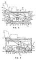
- La figure 2 est une vue de côté du chariot de la présente invention illustrant le montage du rail d'échappement et de la vis sans fin.
- La figure 3 est une vue de côté similaire à la figure 2 représentant une autre réalisation du montage de la vis sans fin.
- La figure 4 est une vue en perspective illustrant principalement la structure et la relation du dispositif fonctionnant en association avec le chariot de la présente invention.
- On se reportera tout d'abord à la figure 1 pour une description détaillée de la présente invention. Les principaux composants du chariot d'imprimante réalisé selon les enseignements de la présente invention sont le châssis 1, un rail excentrique réglable gauche 2, un rail excentrique réglable droit 3 et une embase 4. Le châssis 1 est de préférence une pièce monobloc moulée en un matériau rigide. Le châssis 1 est composé d'un fond 5, de nervures 6, 7 et 8 et de montants 9 et 10 perpendiculaires au fond 5. Des canaux 11 et 12 sont moulés dans la face inférieure du fond 5 et reçoivent les rails d'échappement 13 et 14 (figure 2) le long desquels s'échappe le châssis 1 lors de la rotation d'une vis sans fin 15. Les rails d'échappement 13 et 14 sont montés entre les côtés du châssis d'une imprimante (non représentée), parallélement à la platine 89 (figure 4) d'une imprimante. Le châssis 1 s'échappe entre les côtés du châssis de l'imprimante pendant l'impression sur un milieu d'enregistrement (non représenté) disposé sur la platine.
- Des découpes en V 16 et 17 sont ménagées dans les parties supérieures des montants 9 et 10, respectivement, pour recevoir des prolongements excentriques 18 et 19.des rails 2 et 3, respectivement. Des ouvertures 20 et 21 sont ménagées dans les extrémités supérieures de la nervure 8 pour recevoir des prolongements excentriques 22 et 23 des rails 2 et 3, respectivement. Les prolongements excentriques 18 et 22 ont le même axe de rotation qui est décalé par rapport à l'axe de rotation du reste du rail 2. D'une manière similaire, les prolongements excentriques 19 et 23 ont le même axe de rotation qui est décalé par rapport à l'axe de rotation du reste du rail 3. Les prolongements 22 et 23 comportent à leur extrémité une rainure transversale 24 et 25 permettant l'utilisation d'un tournevis pour tourner les rails 2 et 3 dans le sens des flèches 26 et 27. Après le réglage des rails 2 et 3, les vis de blocage 28 et 29 sont serrées contre les prolongements 22 et 23 pour bloquer les rails 2 et 3 en position ajustée.
- Les ouvertures 20 et 21 présentent des parties en forme de V orientées vers l'intérieur et vers le bas. Les prolongements 22 et 23 sont poussés dans les parties en forme de V lorsque les vis de blocage 28 et 29 sont serrées.
- Comme on l'expliquera en détail utérieure- ment, le chariot porte-cartouches 90 (figure 4) peut être monté sur les rails excentriques 2 et 3. Ce chariot porte-cartouches 90 est mobile sur les rails 2 et 3 vers et depuis la platine 89.
- Une découpe 30 orientée vers le bas est ménagée dans la moitié supérieure de la nervure 8 et se termine par une ouverture circulaire 31 traversant le nervure 8. La découpe 30 et l'ouverture 31 sont prévues pour recevoir un moyen de réglage du chariot porte-cartouches 90 sur les rails 2 et 3. Dans le cas où le moyen de réglage consiste en une vis de réglage, la pointe de ladite vis est vissée dans le trou 107 fileté dans le chariot porte-cartouches 90 et la queue de la vis de réglage peut ainsi tourner librement dans l'ouverture 31. Dans ce cas, la découpe 30 permet la séparation du châssis 1 du chariot porte-cartouches 90 sans à avoir à retirer la vis de l'alésage 107.
- On se reportera maintenant à la fois aux figures 1 et 2. L'embase 4 est de préférence une pièce monobloc moulée en matériau rigide. L'embase 4 se présente sous la forme d'un panneau 34 à nervures perpendiculaires 32 et 33. Des trous 35, 36, 37 et 45 sont usinés au travers de panneau 34 et des nervures 32 et 33 pour recevoir des vis ou des rivets tels que 38 et 39. Les extrémités des rivets 38 et 39 sont fixées dans les lèvres 40 et 41 des canaux 11 et 12. Une lame flexible 42 est fixée sur les nervures 32 et 33 par les vis 43 et 44 et s'étend entre ces nervures. La lame flexible 42 est prévue pour porter un suiveur à gorges de vis sans fin 46 et l'appliquer en engagement contre la vis sans fin 15.
- En raison de la pression appliquée par la lame flexible 42, le suiveur 46 est maintenu en place contre la lame flexible 42 par la friction. Le suiveur 46 pourrait également être fixé à la lame flexible 42 par des vis ou par tout autre moyen approprié. Les extrémités 47 et 48 du panneau 34 ont pour but de maintenir les rails d'échappement 13 et 14 dans les canaux 11 et 12, respectivement. Le canal 11 présente une cannelure 49 glissant sur le rail d'échappement 13 lors de l'échappement du châssis 1. Le canal 12 présente deux surfaces portantes longitudinales incurvées 50 et 51 que ont pour fonction de positioner le châssis 1 sur les rails d'échappement 13 et 14 et de glisser sur le rail 14 lors de l'échappement du châssis 1.
- La partie supérieure de panneau 34 adjacente aux rails d'échappement 13 et 14 peut également faire fonction de surface portante pour ceux-ci. On pourra utiliser d'autres moyens de maintien à la place des portées 49, 50, 51 et de la partie supérieure du panneau 34, qui pourraient être par exemple des roulements à billes.
- Des moyens pour fixer les extrémités des ressorts de tension sont prévus de chaque côté du châssis 1. La figure 1 représente ces moyens de fixation sour la forme des trous 52 et 53 ménagés dans la côté gauche du châssis 1. Seul le trou 54 correspondant au trou 52, est représenté dans le côté droit du châssis 1. La figure 2 représente ces moyens de fixation sour la forme des attaches 55 et 56. Une extrémité du ressort 57 est fixée à l'attache 55 et l'autre au têton 58 qui est fixé dans une position adjacente à l'extrémité arrière 59 du chariot 90 portant l'élément d'impression et les cartouches de ruban. Une extrémité d'un autre ressort 60 est fixée à l'attache 56 et l'autre au téton 61 qui est fixé à un moteur de sélection 62 rappelé vers le bas et vers la droite par ledit ressort 60. D'une manière similaire, le ressort 57 assure le rappel du chariot porte-cartouches 90 vers le bas et vers la droite.
- On se reportera maintenant à la figure 3 qui représente un agencement de montage différent du châssis 1 sur les rails d'échappement 13 et 14 et la vis sans fin 15. Les différences principales du châssis résident dans les lèvres 65, 66, 67 et 68 des canaux de la figure 3 qui sont plus longues que les lèvres correspondantes 63, 40, 41 et 64 de la figure 2. En outre, la lèvre 67 présente un évidement dans lequel sont fixées deux plaques flexibles 71 et 72 par l'intermédiaire de la vis 73, que définissent entre elles un passage circulaire dont les demi- côtés 74-75 présentent des gorges et des intervalles entre gorge correspondant au filetage de la vis sans fin 15.
- L'embase 70 de la figure 3 est quelque peu différente de l'embase 4 de la figure 2 et est formée d'un panneau 69 présentant des alésages 76 et 77 pour le passage des vis de fixation, des découpes 78 et 79 recevant des profils de calage et des découpes 80 et 81 recevant des portées. Les alésages 76 et 77 permettant le passage des vis 82 et 83 vissées dans le châssis 1 pour fixer le panneau 69 à celui-ci. Les portées 84 et 85 sont logées dans les découpes 80 et 81 et supportent les rails d'échappement 13 et 14. Les découpes 78 et 79 reçoivent des profils 86 et 87 solidaires des lèvres 66 et 67 pour le calage de celles-ci.
- Bien que n'étant pas représenté, un meilleur mode d'association du support de montage formé des toles flexibles 71 et 72 à la vis sans fin 15 pourrait consister à rajouter une structure de support inférieure au châssis 1 afin de pouvoir agencer ce support de montage verticalement.
- On se reportera maintenant à la figure 4 qui représente un dispositif qui fonctionne en association avec le châssis 1 et les rails excentriques 2 et 3. Le chariot 90 portant l'élément d'impression et la cartouche de ruban est monté sur le châssis 1 et plus particulièrement sur les rails excentriques 2 et 3. Il présente des supports 88 et 91. Le support 88 présente un évidement à épaulements angulaires 92 en saillie suffisamment proches l'un de l'autre pour porter contre la circonférence de rail excentrique 2 lorsque le chariot 90 est disposé sur ledit rail d'échappement. Le support 91 présente des épaulements 93 similaires mais un peu plus éloignés l'un de l'autre. L'intervalle entre les épaulements 92 assure le positionnement du chariot 90 sur le rail 2. L'intervalle séparant les épaulements 93 permet le mouvement horizontal du chariot 90 sur le châssis 1 le long des rails 13 et 14 lors du réglage du rail excentrique 2. Des supports supplémentaires non représentés similaires aux supports 88 et 91 sont disposés sous la lèvre 94 et adjacents à ses extrémités.
- Lorsque le chariot porte-cartouches 90 est disposé sur les rails excentriques 2 et 3 et que ceux-ci sont réglés, le chariot 90 est orienté par rapport à la platine 89 que est maintenue dans le châssis de l'imprimante (non représenté) parallèlement aux rails d'échappement 13 et 14 et à la vis sans fin 15. En ce qui concerne l'orientation verticale du chariot porte-cartouches 90, les rails 2 et 3 ainsi que leurs réglages sont pratiquement indépendants les uns des autres. Il en est ainsi, que le chariot 90 soit disposé côte-à-côte avec la platine 89 ou verticalement par rapport à celle-ci. En supposant que les divers composants de chariot sont parfaits et que les positions en rotation des rails 2 et 3 sont identiques et en ignorant le mouvement horizontal du chariot 90, le réglage de l'un des rails 2 et 3 entraînera une orientation latérale du chariot 90. Si les deux rails 2 et 3 sont réglés d'une manière similaire, le chariot 90 ne sera orienté que verticalement par rapport à la platine 89. On ne traitera maintenant que de l'orientation verticale du chariot.
- Le chariot porte-cartouches 90 présente un boîtier 95 recevant une cartouche d'élément d'impression démontable 100. La cartouche 100 contient un élément d'impression en forme de margeurite (not représenté) également démontable. La cartouche d'élément d'impression 100 étant disposée dan le boîtier 95 du chariot porte-cartouches 90, le réglage des rails extentriques 2 et 3 provoque également l'orientation latérale (96 à 97 ou 97 à 96) ou verticale de l'écran presse papier 98 de la cartouche d'élément d'impression 100 par rapport à la platine 89.
- Le moteur de sélection 62 comportant un arbre 99 et des éléments de montage 101 et 102, peut également être installé sur les rails excentriques 2 et 3 et orienté par le réglage de ceux-ci. Bien que n'étant pas représenté pour simplifier la figure, un marteau de frappe est fixé sur le haut du moteur de sélection 62 pour frapper l'élément d'impression contenu dans la cartouche 100 et provoquer l'impression sur le milieu porté par la platine 89. Des supports similaires aux supports 88 et 91 sont disposés sur l'extrémité des éléments de montage 101 et 102. Par example, le support 103 est similaire au support 88. Le moyeu d'entraînement 104 est fixé à l'extrémité de l'arbre 99 pour entraîner en rotation l'élément d'impression contenu dans la cartouche 100 pendant une opération d'impression. Le moteur 62 porte donc à la fois l'élément d'impression et le marteau de frappe pendant l'impression. Etant donné que le moteur 62 est monté sur les rails excentriques 2 et 3, le réglage de ceux-ci provoque également l'orientation du moteur, de marteau de frappe et de l'élément d'impression par rapport à la platine 89.
- Des découpes 105 et 106 sont ménagées dans la partie arrière du chariot porte-cartouches 90 et reçoivent un support de montage 1 1 que porte une cartouche de ruban 110.
- Les moyens de réglage traversant les passages 31 et 107 ont pour fonction d'assurer le réglage de la distance séparant l'écran presse papier 98 de la platine 89 afin de faciliter la manipulation du papier. Si plusieurs feuilles de papier avec des feuilles de papier carbone intercalées, doivent être imprimées, la distance séparant l'écran presse-papier 98 de la platine 89 doit être plus grande que lorsqu'une seule feuille est imprimée. La vis à tête traversant les passages 31 et 107 constitue un moyen de réglage facile et rapide de cette distance qui facilite la manipulation du papier.
- La figure 4 représente également des ressorts 108 et 109 qui ont la même fonction que tes ressorts 57 et 60.
- Bien que l'on ait décrit dans ce que précède et représenté sur les dessins les caractéristiques essentielles de l'invention appliquées à des modes de réalisation préférés de celle-ci, il est évident que l'homme de l'art peut y apporter toutes modifications substituant des moyens équivalents dans le cadre de la protection tell que définie par les revendications.
Claims (10)
Applications Claiming Priority (2)
| Application Number | Priority Date | Filing Date | Title |
|---|---|---|---|
| US06/053,646 US4278356A (en) | 1979-06-29 | 1979-06-29 | Daisy wheel printer carrier |
| US53646 | 1987-05-26 |
Publications (2)
| Publication Number | Publication Date |
|---|---|
| EP0020977A1 EP0020977A1 (fr) | 1981-01-07 |
| EP0020977B1 true EP0020977B1 (fr) | 1984-09-12 |
Family
ID=21985661
Family Applications (1)
| Application Number | Title | Priority Date | Filing Date |
|---|---|---|---|
| EP80102569A Expired EP0020977B1 (fr) | 1979-06-29 | 1980-05-09 | Chariot d'imprimante à roue d'impression en forme de marguerite |
Country Status (6)
| Country | Link |
|---|---|
| US (1) | US4278356A (fr) |
| EP (1) | EP0020977B1 (fr) |
| JP (1) | JPS6029357B2 (fr) |
| CA (1) | CA1127105A (fr) |
| DE (1) | DE3069132D1 (fr) |
| IT (1) | IT1151086B (fr) |
Families Citing this family (1)
| Publication number | Priority date | Publication date | Assignee | Title |
|---|---|---|---|---|
| JPS595083A (ja) * | 1982-06-30 | 1984-01-11 | Tokyo Electric Co Ltd | シリアルプリンタ |
Family Cites Families (7)
| Publication number | Priority date | Publication date | Assignee | Title |
|---|---|---|---|---|
| US3715021A (en) * | 1970-11-27 | 1973-02-06 | Burroughs Corp | Variable drive apparatus |
| DE2438735C3 (de) * | 1974-08-13 | 1981-09-10 | Philips Patentverwaltung Gmbh, 2000 Hamburg | Seriendruckwerk |
| US3960256A (en) * | 1974-10-21 | 1976-06-01 | Digital Equipment Corporation | Adjustable carriage apparatus |
| US4114750A (en) * | 1975-08-06 | 1978-09-19 | Hydra Corporation | Printer system having local control for dynamically alterable printing |
| US4124312A (en) * | 1977-02-10 | 1978-11-07 | Xerox Corporation | Impact printer with print wheel cartridge |
| US4127335A (en) * | 1977-02-10 | 1978-11-28 | Xerox Corporation | Impact printer with cartridge print wheel |
| US4134695A (en) * | 1977-07-13 | 1979-01-16 | Teletype Corporation | Printer carriage |
-
1979
- 1979-06-29 US US06/053,646 patent/US4278356A/en not_active Expired - Lifetime
-
1980
- 1980-04-14 CA CA349,754A patent/CA1127105A/fr not_active Expired
- 1980-04-18 JP JP55050519A patent/JPS6029357B2/ja not_active Expired
- 1980-05-09 DE DE8080102569T patent/DE3069132D1/de not_active Expired
- 1980-05-09 EP EP80102569A patent/EP0020977B1/fr not_active Expired
- 1980-05-30 IT IT22423/80A patent/IT1151086B/it active
Also Published As
| Publication number | Publication date |
|---|---|
| US4278356A (en) | 1981-07-14 |
| EP0020977A1 (fr) | 1981-01-07 |
| JPS5610478A (en) | 1981-02-02 |
| JPS6029357B2 (ja) | 1985-07-10 |
| CA1127105A (fr) | 1982-07-06 |
| IT8022423A0 (it) | 1980-05-30 |
| DE3069132D1 (en) | 1984-10-18 |
| IT1151086B (it) | 1986-12-17 |
Similar Documents
| Publication | Publication Date | Title |
|---|---|---|
| FR2509667A1 (fr) | Mecanisme de support d'une tete d'impression thermique d'une imprimante thermique | |
| FR2767499A1 (fr) | Dispositif d'impression sur bande | |
| CA2330809C (fr) | Dispositif pour imprimer un signe et machine a affranchir le comportant | |
| EP0020977B1 (fr) | Chariot d'imprimante à roue d'impression en forme de marguerite | |
| US20120026268A1 (en) | Printhead Adjustment Mechanism for Edge Justified Printer | |
| EP1755895B1 (fr) | Encrier pour machine d'impression | |
| CN1315654C (zh) | 带子打印设备 | |
| EP0020996B1 (fr) | Chariot porte-cartouches d'élément d'impression et de ruban | |
| FR2698585A1 (fr) | Procédé et appareil de réglage d'une tête d'impression. | |
| FR2795013A1 (fr) | Outil de centrage et de serrage | |
| FR2489750A1 (fr) | Marteau pour imprimante a matrice de points | |
| EP0916489A1 (fr) | Dispositif pour le positionnement et la fixation d'outils sur une plaque de support et de chauffage | |
| EP0020979B1 (fr) | Procédé et dispositif d'accouplement et de désaccouplement d'un moteur et d'un élément d'impression | |
| FR2571692A1 (fr) | Etiqueteuse manuelle | |
| EP0013346A1 (fr) | Cartouche pour roue d'impression à languettes porte-caractères radiales | |
| EP1854635A1 (fr) | Unité d'impression à support déformable | |
| JP2004034305A (ja) | 印字装置 | |
| CH630007A5 (fr) | Ensemble de rangement pour disque d'impression. | |
| EP0023270A1 (fr) | Imprimante par points comportant une tête d'impression basculante | |
| EP0048311A1 (fr) | Dispositif de mise en place et de fixation d'un disque d'impression | |
| FR3117992A1 (fr) | Accessoire de support pour vélocipède | |
| FR2565154A1 (fr) | Dispositif de rasage | |
| FR2680722A1 (fr) | Tete d'impression thermique. | |
| FR2783458A1 (fr) | Dispositif pour reguler la pression des tetes dans une imprimante miniature | |
| WO1988005940A1 (fr) | Support pour la combinaison d'un micro-ordinateur et une imprimante |
Legal Events
| Date | Code | Title | Description |
|---|---|---|---|
| PUAI | Public reference made under article 153(3) epc to a published international application that has entered the european phase |
Free format text: ORIGINAL CODE: 0009012 |
|
| AK | Designated contracting states |
Designated state(s): DE FR GB |
|
| 17P | Request for examination filed |
Effective date: 19810205 |
|
| GRAA | (expected) grant |
Free format text: ORIGINAL CODE: 0009210 |
|
| AK | Designated contracting states |
Designated state(s): DE FR GB |
|
| REF | Corresponds to: |
Ref document number: 3069132 Country of ref document: DE Date of ref document: 19841018 |
|
| PLBE | No opposition filed within time limit |
Free format text: ORIGINAL CODE: 0009261 |
|
| STAA | Information on the status of an ep patent application or granted ep patent |
Free format text: STATUS: NO OPPOSITION FILED WITHIN TIME LIMIT |
|
| 26N | No opposition filed | ||
| PGFP | Annual fee paid to national office [announced via postgrant information from national office to epo] |
Ref country code: GB Payment date: 19900404 Year of fee payment: 11 |
|
| PGFP | Annual fee paid to national office [announced via postgrant information from national office to epo] |
Ref country code: FR Payment date: 19900424 Year of fee payment: 11 |
|
| PGFP | Annual fee paid to national office [announced via postgrant information from national office to epo] |
Ref country code: DE Payment date: 19900529 Year of fee payment: 11 |
|
| PG25 | Lapsed in a contracting state [announced via postgrant information from national office to epo] |
Ref country code: GB Effective date: 19910509 |
|
| GBPC | Gb: european patent ceased through non-payment of renewal fee | ||
| PG25 | Lapsed in a contracting state [announced via postgrant information from national office to epo] |
Ref country code: FR Effective date: 19920131 |
|
| PG25 | Lapsed in a contracting state [announced via postgrant information from national office to epo] |
Ref country code: DE Effective date: 19920303 |
|
| REG | Reference to a national code |
Ref country code: FR Ref legal event code: ST |