EP0021002A1 - Dosage de l'encre au moyen de lames d'encrage individuelles s'étendant chacune sur toute la largeur de la région de réglage - Google Patents
Dosage de l'encre au moyen de lames d'encrage individuelles s'étendant chacune sur toute la largeur de la région de réglage Download PDFInfo
- Publication number
- EP0021002A1 EP0021002A1 EP80102669A EP80102669A EP0021002A1 EP 0021002 A1 EP0021002 A1 EP 0021002A1 EP 80102669 A EP80102669 A EP 80102669A EP 80102669 A EP80102669 A EP 80102669A EP 0021002 A1 EP0021002 A1 EP 0021002A1
- Authority
- EP
- European Patent Office
- Prior art keywords
- metering
- ink fountain
- support
- fountain roller
- ink
- Prior art date
- Legal status (The legal status is an assumption and is not a legal conclusion. Google has not performed a legal analysis and makes no representation as to the accuracy of the status listed.)
- Granted
Links
Images



Classifications
-
- B—PERFORMING OPERATIONS; TRANSPORTING
- B41—PRINTING; LINING MACHINES; TYPEWRITERS; STAMPS
- B41F—PRINTING MACHINES OR PRESSES
- B41F31/00—Inking arrangements or devices
- B41F31/02—Ducts, containers, supply or metering devices
- B41F31/04—Ducts, containers, supply or metering devices with duct-blades or like metering devices
Definitions
- the invention relates to an ink fountain for offset or high-pressure machines with an ink metering device which consists of a large number of metering elements arranged close to one another, zone-wide and adjustable to zonal different ink gap thicknesses, which have support and metering areas and whose support areas are under spring pressure on the ink fountain roller, either directly or indirectly.
- each zone-wide metering element in the axial direction of the ink fountain roller has side by side support and metering areas.
- This known device has a number of advantages, for example the independent, resilient support of each individual metering element on the ink fountain roller enables control of the ink film thickness of adjacent zones which does not influence one another. Fluctuations in the ink film thickness due to the ink fountain roller running out of alignment are absolutely eliminated.
- the known device thus offers the basis for a reproducible, sensitive, zone-by-zone determination of the color gap.
- the support and metering areas are arranged next to each other, color-free stripes on the ink fountain roller cannot be avoided.
- the object of the invention is to prevent the formation of color-free stripes on the ink fountain roller due to the constant contact of the support areas while maintaining all the advantages of a device according to DE-AS 26 48 098.
- the invention consists in the fact that the metering area is seen in the direction of rotation of the ink fountain roller, is arranged downstream of the support area, and that the metering area of each metering element extends over the full range Zone width extends.
- the ink under dynamic pressure can expand in the axial direction of the ink fountain roller, as a result of which the color-free strips produced by the support areas are refilled with paint. There is thus no need for additional rubbing in order to eliminate any harmful influence which the color-free strips may have on the inking of the printing plate.
- the ink metering device 6 is located at the lower end of the pressure bars 5. It essentially consists of the metering elements 7, which are arranged axially parallel to the ink fountain roller 4, close together.
- the pressure bars 5 and the metering elements 7 are covered by an elastic film 8 which is attached to the pressure bars 5 in the upper region of the ink fountain 1.
- the printing ink 9 is located in the wedge-shaped space between the elastic film 8, the side walls 3 of the ink fountain 1 and the ink fountain roller 4.
- Each zone-wide printing strip 5 is supported on a compression spring 10 provided in the base plate 2 of the ink fountain 1.
- the screws mentioned above give each pressure bar 5 so much freedom in the vertical direction that the metering elements 7 are constantly pressed against the lateral surface 11 of the ink fountain roller 4 with the interposition of the elastic film 8.
- Each metering element 7 is adjustable about its longitudinal axis via an adjusting arm 12, a link J 3, an adjusting nut 14 and a zone adjusting screw 15 which is rotatably arranged in the ink fountain 1.
- the adjustment range includes the 0 position, in which no color is let through in the respective zone - this position is shown in FIG. 1 - and all other settings up to the maximum ink layer thickness.
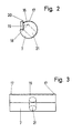
- the metering element 7 is, as in FIGS. 2 and 3 ins show special, cylindrical, but has on a part of its circumference a flattening or eccentric turning, the so-called flow-through groove 16.
- a secant recess 18 is provided in the cylindrical metering element 7, offset from the flow-through groove 16 and thus also to the support areas 17, in which a metering knife 19 is provided which extends over the entire length of the metering element 7.
- the scraper edge 20 of this metering knife 19 represents the metering area and rises at least up to a plane with the part of the support areas 17 which rises highest above the flow-through groove 16.
- the metering element 7 also has a bore 21 into which the actuating arm 12 projects.
- the elastic film 8 not only covers all pressure bars 5, but, as mentioned, also the metering elements 7 as far as beyond the scraper edge 20 of the metering knives 19.
- a cover plate 22 is provided on the ink fountain 1. Its upper, free end 23, which is angled toward the metering elements 7, is still covered by the elastic film 8.
- the associated metering element 7 is adjusted about its longitudinal axis in such a way that the gap between the scraper edge 20 of the zone-wide metering knife 19 and the lateral surface 11 of the ink fountain roller 4 is changed.
- the elastic film adapts to the setting of the metering knife 19, i.e. , due to the hydrodynamic pressure of the paint 9, it is constantly on the stripping edge 20 of the metering knife 19. The position of the metering knife 19 thus determines the color strip thickness of this zone.
- the metering knife 9 is provided so far from the contact point 24 of the support areas 17 that the space is large enough to deflect the elastic film due to the dynamic pressure, so that the paint 9 flows in the axial direction into the area in which the support areas 17 pass their permanent system produce a color-free streak on the jacket 1 of the ink fountain roller 4.
- a zone-wide, continuous ink layer thickness is thus generated due to the offset arrangement of the zone-wide metering knives 19.
- FIG. 4 differs from the one described above primarily only in that the metering elements 7 of the ink metering device 6 have been given a flat-shaped design.
- Fig. 5 shows a cross section through such a flat piece.
- the metering elements 7 are used here as a slide.
- the zone adjusting screw 15 projects into a threaded bore 25 of the metering element 7 and, when it is rotated, causes a tangential adjustment of the metering element 7 relative to the ink fountain roller 4.
- a leaf spring 26 fastened in the ink fountain 1 presses the associated metering element 7 continuously in the direction of the ink fountain roller 4
- the metering element 7 is supported here via rib-shaped support areas 17 with the interposition of the elastic film 8 on the lateral surface 11 of the ink fountain roller 4.
- a zone-wide metering knife 19 is attached to the front end wall 27 of each metering element 7 designed as a flat piece. Its scraper edge 20 projects beyond the support areas 17. The height of the scraper edge 20 must be such that, in the 0 position of the metering element 7, the scraper edge 20 and the support areas 17 simultaneously abut the lateral surface 11 of the ink fountain roller 4. In this embodiment, too, all the metering elements 7 are covered by the elastic film 8 beyond the metering knives 19. Scraper edge 20 and support areas 17 thus never lie directly against the lateral surface 11.
- the gap between the stripping edge 20 including the overlying film 8 and the outer surface 11 of the ink fountain roller 4 is changed in the respective zone.
- the support areas are always indirectly in contact with the outer surface 11 of the ink fountain roller 4, the color-free strips produced thereby cannot have a disadvantageous effect because in the space between the support areas 17 and the wiping edge 20, the ink 9 under back pressure is the color-free area generated by the support areas 17 replenishes.
- FIG. 6 The embodiment of an ink fountain 1 shown in FIG. 6 with an ink metering device 6 according to the invention shows metering elements 7 consisting of two parts, u. between. Zone width and pressure bars 5 which are under pressure from a spring 10 are provided here on the base plate 2 of the ink fountain 1, exactly as in the embodiment according to FIG. 1. At their front end, however, these pressure strips 5 have support areas 17, by means of which they are located on the lateral surface 1 of the ink fountain with the interposition of the film 8 Support roller 4.
- a cylindrical rotary valve 30 is rotatably mounted about its longitudinal axis. It also runs coaxially with the ink fountain roller 4.
- the rotary valve 30 consists of a cylinder which has exactly the length of the zone width and is eccentrically turned over a certain circumferential range. In its concentric area, it is supported in a slide bearing 31 of the pressure bar 5.
- the eccentrically turned off portion 32 can be juxtaposed with the ink fountain roller 4 by adjusting means. The eccentricity of this turned surface causes a gap of different size to be formed over the entire zone width, depending on the setting between the elastic film 8 covering the pressure bar 5 and the rotary valve 30 and the lateral surface 11 1 of the ink fountain roller 4.
- a flattening could also be used as the metering surface.
- Each zone-wide rotary valve 30 can be rotated about its longitudinal axis via an adjusting arm 12, a link 13, an adjusting nut 14 and a zone adjusting screw 15.
- the zone adjusting screw 15 can be actuated not only via the handwheel 33, but also via the servomotor 34 for remote adjustment.
- the respective position of the zone screw 15 and thus the angular position of the rotary valve 30 is reported by the potentiometer 35 actuated by the zone adjusting screw J 5 to a display, control or regulating device, not shown.
- FIG. 7 shows an ink fountain 1 with an ink fountain roller 4 immersed in the ink 9 and an ink metering device 6 provided above the ink fountain 1.
- the latter consists of a series of metering elements 7 arranged over the length of the ink fountain 1, which are designed as doctor-wide doctor blades.
- a traverse 36 running parallel to the ink fountain roller 4 adjusting nuts 37 are rotatably mounted for each zone, into which a threaded bolt 38 projects, the free end of which is connected to a sliding claw 39 in which the doctor-shaped metering element 7 is fastened.
- a leaf spring 40 provided in the crossmember 36 bears against the underside of the doctor-shaped metering element 7 and presses it in the direction of the lateral surface 11 of the ink fountain roller 4.
- the front end of the metering element 7 is provided with a scraper edge 20 and also has an end face, as in particular 8 shows two support arms 41 on which support rollers 42 are rotatably mounted. These support rollers 42 run on the lateral surface 11 of the ink fountain roller 4.
- the respective position of the doctor-shaped metering element 7 in the vertical direction determines the distance of the scraper edge 20 from the lateral surface 11 of the ink fountain roller 4. In the lower position shown in solid lines, the scraper edge 20 lies against the lateral surface 11 and thus does not allow any color to pass.
- the doctor-shaped metering element 7 is moved vertically upward, for example into the line dotted layer 43, the support rollers 41 still have contact with the lateral surface 11 of the ink fountain roller 4, since the leaf spring 40 presses the metering element 7 in the direction of the ink fountain roller 4.
- the support rollers 42 are in front of the stripping edge 20, the color-free stripes produced by them can be refilled with paint from the stripping edge 20.
- the dosing elements 7 are provided outside the ink fountain 1 and above the mirror of the ink 9, they do not need to be covered by a film 8. All zone-wide metering elements 7 are arranged side by side, directly adjacent to one another. This guarantees a completely independent, streak-free setting of the color film of each zone.
- each zone-wide doctor-shaped metering element 7 can be supported directly on support surface 41 on the lateral surface 11 of the ink fountain roller 4. The support rollers 42 are then unnecessary.
- each metering element 7 is applied to the ink fountain roller 4 on its own, ie independently of the others. But there is also the possibility to connect several pressure strips 5 together and together by a spring organ against the ink fountain roller 4. In addition, it has been shown that a distance of approximately 4 mm must be provided between the support point 24 and the scraper edge 20 in order to ensure adequate filling of the color-free strips. But it is quite conceivable that this distance can be reduced by special design of the support areas 17.
- Another possible modification of the invention is that the rotary valve 30 in the embodiment according to FIG. 6 is replaced by other valve designs.
Landscapes
- Inking, Control Or Cleaning Of Printing Machines (AREA)
- Cosmetics (AREA)
- Medicinal Preparation (AREA)
- Mechanical Pencils And Projecting And Retracting Systems Therefor, And Multi-System Writing Instruments (AREA)
- Coating Apparatus (AREA)
Priority Applications (1)
| Application Number | Priority Date | Filing Date | Title |
|---|---|---|---|
| AT80102669T ATE6138T1 (de) | 1979-06-12 | 1980-05-13 | Farbdosierung mit einzelnen, jeweils ueber die gesamte zonenbreite reichenden farbmessern. |
Applications Claiming Priority (2)
| Application Number | Priority Date | Filing Date | Title |
|---|---|---|---|
| DE2923678A DE2923678C2 (de) | 1979-06-12 | 1979-06-12 | Farbkasten mit einzelnen, jeweils über die gesamte Zonenbreite reichenden Farbdosiereinrichtungen |
| DE2923678 | 1979-06-12 |
Publications (2)
| Publication Number | Publication Date |
|---|---|
| EP0021002A1 true EP0021002A1 (fr) | 1981-01-07 |
| EP0021002B1 EP0021002B1 (fr) | 1984-02-08 |
Family
ID=6073013
Family Applications (1)
| Application Number | Title | Priority Date | Filing Date |
|---|---|---|---|
| EP80102669A Expired EP0021002B1 (fr) | 1979-06-12 | 1980-05-13 | Dosage de l'encre au moyen de lames d'encrage individuelles s'étendant chacune sur toute la largeur de la région de réglage |
Country Status (13)
| Country | Link |
|---|---|
| US (1) | US4387648A (fr) |
| EP (1) | EP0021002B1 (fr) |
| JP (1) | JPS562171A (fr) |
| AR (1) | AR225924A1 (fr) |
| AT (1) | ATE6138T1 (fr) |
| AU (1) | AU529374B2 (fr) |
| CA (1) | CA1128812A (fr) |
| DE (2) | DE2923678C2 (fr) |
| DK (1) | DK146379C (fr) |
| ES (1) | ES8101467A1 (fr) |
| IT (1) | IT8053294V0 (fr) |
| NO (1) | NO151186C (fr) |
| ZA (1) | ZA803515B (fr) |
Cited By (6)
| Publication number | Priority date | Publication date | Assignee | Title |
|---|---|---|---|---|
| EP0085164A1 (fr) * | 1982-02-03 | 1983-08-10 | Heidelberger Druckmaschinen Aktiengesellschaft | Lame d'encrage et dispositif de réglage de la lame dans l'encrier des machines d'impression rotatives |
| EP0093879A1 (fr) * | 1982-05-11 | 1983-11-16 | Heidelberger Druckmaschinen Aktiengesellschaft | Procédé et dispositif de dosage d'encre dans les rotatives offset |
| FR2568180A1 (fr) * | 1984-07-28 | 1986-01-31 | Roland Man Druckmasch | Dispositif de dosage d'encre |
| EP0131106A3 (en) * | 1983-07-11 | 1986-10-29 | M.A.N.-Roland Druckmaschinen Aktiengesellschaft | Inking device for a printing machine |
| EP0190600A3 (en) * | 1985-02-04 | 1988-07-20 | M.A.N.-Roland Druckmaschinen Aktiengesellschaft | Ink-metering device for printing machines |
| EP0919380A1 (fr) * | 1997-11-24 | 1999-06-02 | Heidelberger Druckmaschinen Aktiengesellschaft | Eléments doseurs dans un bac à encre pour des presses rotatives |
Families Citing this family (12)
| Publication number | Priority date | Publication date | Assignee | Title |
|---|---|---|---|---|
| DD209777A1 (de) * | 1982-09-21 | 1984-05-23 | Arndt Jentzsch | Farbdosiereinrichtung |
| DE3308066C1 (de) * | 1983-03-08 | 1984-09-13 | M.A.N.- Roland Druckmaschinen AG, 6050 Offenbach | Farbdosiervorrichtung fuer eine Farbkastenwalze |
| DE3311113C1 (de) * | 1983-03-26 | 1988-05-05 | M.A.N.- Roland Druckmaschinen AG, 6050 Offenbach | Dosierelemente in Farbkaesten von Offsetdruckmaschinen |
| DE3538256A1 (de) * | 1985-10-28 | 1987-04-30 | Heidelberger Druckmasch Ag | Farbkasten fuer offset- oder hochdruckmaschinen |
| CH677211A5 (fr) * | 1988-05-31 | 1991-04-30 | Bobst Sa | |
| US5233922A (en) * | 1991-01-10 | 1993-08-10 | Belgium Tool And Die Company | Ink fountain for a can coater |
| JPH07107277B2 (ja) * | 1992-01-28 | 1995-11-15 | エスコ・コーポレイション | ドラグラインバケット及びその操作方法 |
| DE19649318A1 (de) * | 1996-11-28 | 1998-06-04 | Heidelberger Druckmasch Ag | Farbkasten für Rotationsdruckmaschinen |
| DE102006062980B3 (de) | 2005-12-12 | 2021-07-29 | Heidelberger Druckmaschinen Intellectual Property Ag & Co. Kg | Detektor zur Schließpunkterfassung im Farbkasten |
| JP2013039748A (ja) * | 2011-08-17 | 2013-02-28 | Komori Corp | インキ供給装置 |
| US9296201B2 (en) * | 2013-03-13 | 2016-03-29 | Probity Engineering, Llc | Ink fountain apparatus and method of adjusting ink flow for a flexographic printing apparatus |
| CN114953723B (zh) * | 2022-06-20 | 2023-06-20 | 安徽工程大学 | 一种自适应印刷机器人 |
Citations (3)
| Publication number | Priority date | Publication date | Assignee | Title |
|---|---|---|---|---|
| CH392566A (de) * | 1961-05-03 | 1965-05-31 | Maschf Augsburg Nuernberg Ag | Rillenfarbwerk für Druckmaschinen |
| DD120833A1 (fr) * | 1975-05-15 | 1976-07-05 | ||
| DE2648098B2 (de) * | 1976-10-23 | 1979-04-05 | Heidelberger Druckmaschinen Ag, 6900 Heidelberg | Farbkasten für Offset- oder Hochdruckmaschinen |
Family Cites Families (5)
| Publication number | Priority date | Publication date | Assignee | Title |
|---|---|---|---|---|
| US3818830A (en) * | 1972-05-15 | 1974-06-25 | Int Machine Prod Inc | Arrangement for supplying ink for a printing machine |
| DE2264119C3 (de) * | 1972-12-29 | 1978-12-07 | Albert-Frankenthal Ag, 6710 Frankenthal | Farbmesser eines Druckmaschinenfarbwerks |
| US4242598A (en) * | 1974-10-02 | 1980-12-30 | Varian Associates, Inc. | Temperature compensating transistor bias device |
| DE2460116C3 (de) * | 1974-12-19 | 1979-09-06 | Heidelberger Druckmaschinen Ag, 6900 Heidelberg | Farbkasten für Druckmaschinen |
| DE2530109C3 (de) * | 1975-07-05 | 1978-05-03 | Heidelberger Druckmaschinen Ag, 6900 Heidelberg | Farbwerk für Druckmaschinen |
-
1979
- 1979-06-12 DE DE2923678A patent/DE2923678C2/de not_active Expired
-
1980
- 1980-05-13 AT AT80102669T patent/ATE6138T1/de not_active IP Right Cessation
- 1980-05-13 EP EP80102669A patent/EP0021002B1/fr not_active Expired
- 1980-05-13 DE DE8080102669T patent/DE3066474D1/de not_active Expired
- 1980-05-27 AU AU58795/80A patent/AU529374B2/en not_active Ceased
- 1980-06-09 AR AR281346A patent/AR225924A1/es active
- 1980-06-10 DK DK249280A patent/DK146379C/da active
- 1980-06-10 CA CA353,716A patent/CA1128812A/fr not_active Expired
- 1980-06-11 IT IT8053294U patent/IT8053294V0/it unknown
- 1980-06-11 ES ES492327A patent/ES8101467A1/es not_active Expired
- 1980-06-11 NO NO801740A patent/NO151186C/no unknown
- 1980-06-12 JP JP7844180A patent/JPS562171A/ja active Granted
- 1980-06-12 US US06/158,785 patent/US4387648A/en not_active Expired - Lifetime
- 1980-06-12 ZA ZA00803515A patent/ZA803515B/xx unknown
Patent Citations (3)
| Publication number | Priority date | Publication date | Assignee | Title |
|---|---|---|---|---|
| CH392566A (de) * | 1961-05-03 | 1965-05-31 | Maschf Augsburg Nuernberg Ag | Rillenfarbwerk für Druckmaschinen |
| DD120833A1 (fr) * | 1975-05-15 | 1976-07-05 | ||
| DE2648098B2 (de) * | 1976-10-23 | 1979-04-05 | Heidelberger Druckmaschinen Ag, 6900 Heidelberg | Farbkasten für Offset- oder Hochdruckmaschinen |
Cited By (9)
| Publication number | Priority date | Publication date | Assignee | Title |
|---|---|---|---|---|
| EP0085164A1 (fr) * | 1982-02-03 | 1983-08-10 | Heidelberger Druckmaschinen Aktiengesellschaft | Lame d'encrage et dispositif de réglage de la lame dans l'encrier des machines d'impression rotatives |
| AT386156B (de) * | 1982-02-03 | 1988-07-11 | Heidelberger Druckmasch Ag | Einstellvorrichtung fuer das farbmesser am farbkasten von rotationsdruckmaschinen |
| EP0093879A1 (fr) * | 1982-05-11 | 1983-11-16 | Heidelberger Druckmaschinen Aktiengesellschaft | Procédé et dispositif de dosage d'encre dans les rotatives offset |
| AT388706B (de) * | 1982-05-11 | 1989-08-25 | Heidelberger Druckmasch Ag | Verfahren und vorrichtung zum dosieren der farbe bei offsetdruckmaschinen |
| EP0131106A3 (en) * | 1983-07-11 | 1986-10-29 | M.A.N.-Roland Druckmaschinen Aktiengesellschaft | Inking device for a printing machine |
| FR2568180A1 (fr) * | 1984-07-28 | 1986-01-31 | Roland Man Druckmasch | Dispositif de dosage d'encre |
| EP0190600A3 (en) * | 1985-02-04 | 1988-07-20 | M.A.N.-Roland Druckmaschinen Aktiengesellschaft | Ink-metering device for printing machines |
| EP0919380A1 (fr) * | 1997-11-24 | 1999-06-02 | Heidelberger Druckmaschinen Aktiengesellschaft | Eléments doseurs dans un bac à encre pour des presses rotatives |
| US5960715A (en) * | 1997-11-24 | 1999-10-05 | Heidelberger Druckmaschinen Ag | Ink duct for rotary printing presses |
Also Published As
| Publication number | Publication date |
|---|---|
| AU529374B2 (en) | 1983-06-02 |
| JPS562171A (en) | 1981-01-10 |
| DE3066474D1 (en) | 1984-03-15 |
| ATE6138T1 (de) | 1984-02-15 |
| DK249280A (da) | 1980-12-13 |
| DK146379B (da) | 1983-09-26 |
| NO151186C (no) | 1985-02-27 |
| AU5879580A (en) | 1980-12-18 |
| AR225924A1 (es) | 1982-05-14 |
| DE2923678C2 (de) | 1982-02-18 |
| ES492327A0 (es) | 1980-12-16 |
| ZA803515B (en) | 1981-06-24 |
| EP0021002B1 (fr) | 1984-02-08 |
| IT8053294V0 (it) | 1980-06-11 |
| NO801740L (no) | 1980-12-15 |
| ES8101467A1 (es) | 1980-12-16 |
| DE2923678A1 (de) | 1980-12-18 |
| CA1128812A (fr) | 1982-08-03 |
| NO151186B (no) | 1984-11-19 |
| DK146379C (da) | 1984-03-05 |
| US4387648A (en) | 1983-06-14 |
| JPS5747028B2 (fr) | 1982-10-06 |
Similar Documents
| Publication | Publication Date | Title |
|---|---|---|
| EP0021002B1 (fr) | Dosage de l'encre au moyen de lames d'encrage individuelles s'étendant chacune sur toute la largeur de la région de réglage | |
| DE2648098C3 (de) | Farbkasten für Offset- oder Hochdruckmaschinen | |
| EP0085164B1 (fr) | Lame d'encrage et dispositif de réglage de la lame dans l'encrier des machines d'impression rotatives | |
| DE4012825C2 (fr) | ||
| DE2228625A1 (de) | Farbmesser fuer druckmaschinen | |
| EP0120298B1 (fr) | Eléments de dosage pour les encriers de machine d'impression offset | |
| EP0019073B1 (fr) | Dispositif d'encrage pour machine à imprimer | |
| DE2230126B2 (de) | Dosiervorrichtung eines Farbkastens an Druckmaschinen | |
| EP1103377B1 (fr) | Dispositif d'étanchéification d'une alimentation en encre dans des machines d'impression | |
| EP0041117B1 (fr) | Lame d'encrier pour un rouleau à bac encreur d'une presse à imprimer | |
| DE9109785U1 (de) | Rakelvorrichtung mit Rakelbalken | |
| DE602005002142T2 (de) | Tintenzuführungsvorrichtung für druckmaschine | |
| DE3239259C2 (de) | Vorrichtung zum zonenweisen Dosieren von Farbe auf der Farbkastenwalze eines Farbwerkes für Druckmaschinen | |
| CH686356A5 (de) | Steuervorrichtung fuer die Farbzufuhr an einer Offsetdruckmaschine. | |
| DE4240642C2 (de) | Farbmesserlamellenhalter und Farbmesser-Lamellen für einen Farbkasten einer Rotationsdruckmaschine | |
| DE3324445A1 (de) | Farbdosiervorrichtung an buch- und offsetdruckmaschinen | |
| EP0845354B1 (fr) | Bac à encre pour presses rotatives | |
| DE69903490T2 (de) | Farbwerk | |
| DE2545737A1 (de) | Farbmesser fuer die farbkastenwalze | |
| EP0022924B1 (fr) | Dispositif de dosage de l'encre dans une machine d'impression | |
| DE19614191A1 (de) | Farbdosiereinrichtung für Farbwerke von Druckmaschinen | |
| DE3844138A1 (de) | Dosiermesser zum zonenweisen dosieren eines farbfilms | |
| DE2950163A1 (de) | Farbkasten fuer eine offset-rotationsdruckmaschine | |
| DE102007053595B4 (de) | Verfahren zur Einstellung einer Farbdosiereinrichtung | |
| DD141971A3 (de) | Farbdosiervorrichtung fuer farbkaesten von druckmaschinen |
Legal Events
| Date | Code | Title | Description |
|---|---|---|---|
| PUAI | Public reference made under article 153(3) epc to a published international application that has entered the european phase |
Free format text: ORIGINAL CODE: 0009012 |
|
| AK | Designated contracting states |
Designated state(s): AT BE CH DE FR GB IT NL SE |
|
| 17P | Request for examination filed |
Effective date: 19810213 |
|
| ITF | It: translation for a ep patent filed | ||
| GRAA | (expected) grant |
Free format text: ORIGINAL CODE: 0009210 |
|
| AK | Designated contracting states |
Designated state(s): AT BE CH DE FR GB IT LI NL SE |
|
| REF | Corresponds to: |
Ref document number: 6138 Country of ref document: AT Date of ref document: 19840215 Kind code of ref document: T |
|
| REF | Corresponds to: |
Ref document number: 3066474 Country of ref document: DE Date of ref document: 19840315 |
|
| ET | Fr: translation filed | ||
| PGFP | Annual fee paid to national office [announced via postgrant information from national office to epo] |
Ref country code: AT Payment date: 19840413 Year of fee payment: 5 |
|
| PGFP | Annual fee paid to national office [announced via postgrant information from national office to epo] |
Ref country code: NL Payment date: 19840531 Year of fee payment: 5 |
|
| PGFP | Annual fee paid to national office [announced via postgrant information from national office to epo] |
Ref country code: BE Payment date: 19840630 Year of fee payment: 5 |
|
| PLBE | No opposition filed within time limit |
Free format text: ORIGINAL CODE: 0009261 |
|
| STAA | Information on the status of an ep patent application or granted ep patent |
Free format text: STATUS: NO OPPOSITION FILED WITHIN TIME LIMIT |
|
| 26N | No opposition filed | ||
| PG25 | Lapsed in a contracting state [announced via postgrant information from national office to epo] |
Ref country code: AT Effective date: 19850513 |
|
| PG25 | Lapsed in a contracting state [announced via postgrant information from national office to epo] |
Ref country code: BE Effective date: 19850531 |
|
| BERE | Be: lapsed |
Owner name: HEIDELBERGER DRUCKMASCHINEN A.G. Effective date: 19850513 |
|
| PG25 | Lapsed in a contracting state [announced via postgrant information from national office to epo] |
Ref country code: NL Effective date: 19851201 |
|
| NLV4 | Nl: lapsed or anulled due to non-payment of the annual fee | ||
| ITTA | It: last paid annual fee | ||
| PGFP | Annual fee paid to national office [announced via postgrant information from national office to epo] |
Ref country code: SE Payment date: 19920507 Year of fee payment: 13 |
|
| PGFP | Annual fee paid to national office [announced via postgrant information from national office to epo] |
Ref country code: DE Payment date: 19920625 Year of fee payment: 13 |
|
| PG25 | Lapsed in a contracting state [announced via postgrant information from national office to epo] |
Ref country code: SE Effective date: 19930514 |
|
| PG25 | Lapsed in a contracting state [announced via postgrant information from national office to epo] |
Ref country code: DE Effective date: 19940201 |
|
| PGFP | Annual fee paid to national office [announced via postgrant information from national office to epo] |
Ref country code: FR Payment date: 19940403 Year of fee payment: 15 |
|
| PGFP | Annual fee paid to national office [announced via postgrant information from national office to epo] |
Ref country code: CH Payment date: 19940609 Year of fee payment: 15 |
|
| EUG | Se: european patent has lapsed |
Ref document number: 80102669.1 Effective date: 19931210 |
|
| PG25 | Lapsed in a contracting state [announced via postgrant information from national office to epo] |
Ref country code: LI Effective date: 19950531 Ref country code: CH Effective date: 19950531 |
|
| REG | Reference to a national code |
Ref country code: CH Ref legal event code: PL |
|
| PG25 | Lapsed in a contracting state [announced via postgrant information from national office to epo] |
Ref country code: FR Effective date: 19960229 |
|
| REG | Reference to a national code |
Ref country code: FR Ref legal event code: ST |
|
| REG | Reference to a national code |
Ref country code: FR Ref legal event code: ST |
|
| PGFP | Annual fee paid to national office [announced via postgrant information from national office to epo] |
Ref country code: GB Payment date: 19970418 Year of fee payment: 18 |
|
| PG25 | Lapsed in a contracting state [announced via postgrant information from national office to epo] |
Ref country code: GB Free format text: LAPSE BECAUSE OF NON-PAYMENT OF DUE FEES Effective date: 19980513 |
|
| GBPC | Gb: european patent ceased through non-payment of renewal fee |
Effective date: 19980513 |