EP0021090B1 - Appareil pour le découpage de plusieurs fibres optiques réunies dans un câble - Google Patents
Appareil pour le découpage de plusieurs fibres optiques réunies dans un câble Download PDFInfo
- Publication number
- EP0021090B1 EP0021090B1 EP80102977A EP80102977A EP0021090B1 EP 0021090 B1 EP0021090 B1 EP 0021090B1 EP 80102977 A EP80102977 A EP 80102977A EP 80102977 A EP80102977 A EP 80102977A EP 0021090 B1 EP0021090 B1 EP 0021090B1
- Authority
- EP
- European Patent Office
- Prior art keywords
- anvil
- waveguides
- light waveguides
- individual
- light
- Prior art date
- Legal status (The legal status is an assumption and is not a legal conclusion. Google has not performed a legal analysis and makes no representation as to the accuracy of the status listed.)
- Expired
Links
- 230000003287 optical effect Effects 0.000 title description 21
- 229910003460 diamond Inorganic materials 0.000 claims description 12
- 239000010432 diamond Substances 0.000 claims description 12
- 230000000284 resting effect Effects 0.000 claims description 2
- 238000006748 scratching Methods 0.000 claims description 2
- 230000002393 scratching effect Effects 0.000 claims description 2
- 230000000694 effects Effects 0.000 claims 1
- 238000000926 separation method Methods 0.000 abstract description 4
- 238000000034 method Methods 0.000 abstract description 3
- 239000013307 optical fiber Substances 0.000 description 62
- 230000006835 compression Effects 0.000 description 6
- 238000007906 compression Methods 0.000 description 6
- 239000004020 conductor Substances 0.000 description 5
- 238000006073 displacement reaction Methods 0.000 description 2
- 239000000835 fiber Substances 0.000 description 2
- 208000036829 Device dislocation Diseases 0.000 description 1
- 241001422033 Thestylus Species 0.000 description 1
- 238000005452 bending Methods 0.000 description 1
- 244000309464 bull Species 0.000 description 1
- 230000007423 decrease Effects 0.000 description 1
- 238000005516 engineering process Methods 0.000 description 1
- 230000003993 interaction Effects 0.000 description 1
- 230000001960 triggered effect Effects 0.000 description 1
Images

Classifications
-
- G—PHYSICS
- G02—OPTICS
- G02B—OPTICAL ELEMENTS, SYSTEMS OR APPARATUS
- G02B6/00—Light guides; Structural details of arrangements comprising light guides and other optical elements, e.g. couplings
- G02B6/24—Coupling light guides
- G02B6/25—Preparing the ends of light guides for coupling, e.g. cutting
-
- Y—GENERAL TAGGING OF NEW TECHNOLOGICAL DEVELOPMENTS; GENERAL TAGGING OF CROSS-SECTIONAL TECHNOLOGIES SPANNING OVER SEVERAL SECTIONS OF THE IPC; TECHNICAL SUBJECTS COVERED BY FORMER USPC CROSS-REFERENCE ART COLLECTIONS [XRACs] AND DIGESTS
- Y10—TECHNICAL SUBJECTS COVERED BY FORMER USPC
- Y10T—TECHNICAL SUBJECTS COVERED BY FORMER US CLASSIFICATION
- Y10T225/00—Severing by tearing or breaking
- Y10T225/10—Methods
- Y10T225/12—With preliminary weakening
-
- Y—GENERAL TAGGING OF NEW TECHNOLOGICAL DEVELOPMENTS; GENERAL TAGGING OF CROSS-SECTIONAL TECHNOLOGIES SPANNING OVER SEVERAL SECTIONS OF THE IPC; TECHNICAL SUBJECTS COVERED BY FORMER USPC CROSS-REFERENCE ART COLLECTIONS [XRACs] AND DIGESTS
- Y10—TECHNICAL SUBJECTS COVERED BY FORMER USPC
- Y10T—TECHNICAL SUBJECTS COVERED BY FORMER US CLASSIFICATION
- Y10T225/00—Severing by tearing or breaking
- Y10T225/30—Breaking or tearing apparatus
- Y10T225/307—Combined with preliminary weakener or with nonbreaking cutter
- Y10T225/321—Preliminary weakener
- Y10T225/325—With means to apply moment of force to weakened work
Definitions
- the ends of the individual optical fibers When making cable connections, the ends of the individual optical fibers must not only lie in a common plane, but the ends must have an optically flat surface that is perpendicular to the longitudinal axis of the optical fibers.
- the ends of the optical fibers are then provided with corresponding end pieces.
- a usable conductor end can be obtained by scratching the conductor and then pulling it. The conductor then breaks at the scratch.
- a device for separating a plurality of optical fibers in which the individual optical fibers are guided in parallel at the point to be separated over an anvil and are tensioned and scored successively by a clamping device acting in the axial direction of the optical fibers.
- the optical fibers are tensioned with the aid of a clamping device which is displaceably arranged relative to a fixed clamping device and which is under the action of an adjustable force of a compression spring.
- the clamping point of the displaceable clamping device is designed as a slip clutch, the clamping force, which corresponds to the frictional force, being adjustable.
- This known clamping device is based on the principle that with increasing distance of the movable clamping point from the fixed, the displacement force of the compression spring decreases accordingly.
- the frictional force of the clamping point is matched to the force of the compression spring so that both forces are in equilibrium.
- the movable clamping device is pivotally mounted and is connected to a torque sensor via a lever system and a force measuring unit.
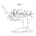
- An anvil with a cylindrical upper surface is used to achieve a cutting plane that runs exactly perpendicular to the axis of the optical waveguide, in which parallel grooves for guiding the individual optical waveguides are incorporated.
- the individual optical fibers at the cable end must, among other things, be untwisted, recognized and brought into the desired positions in order to be able to connect them to corresponding optical fibers of another cable or the like.
- Most of the cable ends are provided with so-called end pieces, in which the individual optical fibers assume a precisely defined position. It is essential here, however, that the individual optical fibers are parallel to one another at the predetermined distance.
- the double-armed lever 25 is provided with a scanning pin in the form of a screw 31, which is able to interact with a fixed template 32.
- the template 32 consists of strings juxtaposed, the number and spacing of which corresponds to the spacing of the grooves 20 in the anvil 4.
- the adjustable with the help of the force measuring unit 9 bias of the individual optical fibers with the help of the pivotable clamping device 5 depends on the number and strength of the individual optical fibers 1.
- the template guide 31, 32 of the double-armed lever 25 can damage the wedge-shaped diamond in the absence of an optical fiber 27 do not occur.
- more or fewer optical fibers can be separated if necessary.
Landscapes
- Physics & Mathematics (AREA)
- General Physics & Mathematics (AREA)
- Optics & Photonics (AREA)
- Mechanical Coupling Of Light Guides (AREA)
- Light Guides In General And Applications Therefor (AREA)
- Processing Of Terminals (AREA)
Claims (10)
Priority Applications (1)
| Application Number | Priority Date | Filing Date | Title |
|---|---|---|---|
| AT80102977T ATE3531T1 (de) | 1979-06-21 | 1980-05-28 | Vorrichtung zum trennen von mehreren in einem kabel vereinigten lichtwellenleitern. |
Applications Claiming Priority (2)
| Application Number | Priority Date | Filing Date | Title |
|---|---|---|---|
| DE2925070 | 1979-06-21 | ||
| DE2925070A DE2925070C2 (de) | 1979-06-21 | 1979-06-21 | Vorrichtung zum Trennen von mehreren in einem Kabel vereinigten Lichtwellenleitern |
Publications (2)
| Publication Number | Publication Date |
|---|---|
| EP0021090A1 EP0021090A1 (fr) | 1981-01-07 |
| EP0021090B1 true EP0021090B1 (fr) | 1983-05-25 |
Family
ID=6073790
Family Applications (1)
| Application Number | Title | Priority Date | Filing Date |
|---|---|---|---|
| EP80102977A Expired EP0021090B1 (fr) | 1979-06-21 | 1980-05-28 | Appareil pour le découpage de plusieurs fibres optiques réunies dans un câble |
Country Status (6)
| Country | Link |
|---|---|
| US (1) | US4315584A (fr) |
| EP (1) | EP0021090B1 (fr) |
| JP (1) | JPS565510A (fr) |
| AT (1) | ATE3531T1 (fr) |
| CA (1) | CA1141217A (fr) |
| DE (1) | DE2925070C2 (fr) |
Families Citing this family (18)
| Publication number | Priority date | Publication date | Assignee | Title |
|---|---|---|---|---|
| DE3017873A1 (de) * | 1980-05-09 | 1981-11-12 | Siemens AG, 1000 Berlin und 8000 München | Verfahren und vorrichtung zum trennen von mehreren in einem kabel vereinigten lichtwellenleitern |
| FR2487812B1 (fr) * | 1980-07-31 | 1985-06-07 | Socapex | Outillage de cassure collective de fibres optiques |
| DE3126852A1 (de) * | 1981-07-08 | 1983-05-26 | AEG-Telefunken Nachrichtentechnik GmbH, 7150 Backnang | Vorrichtung zum trennen von lichtleitfasern |
| CA1166217A (fr) * | 1981-07-10 | 1984-04-24 | Helmut H. Lukas | Methode et dispositif de fractionnement de fibres optiques |
| US4503744A (en) * | 1982-03-22 | 1985-03-12 | Thomas & Betts Corporation | Cleaving device for optical fibers |
| US4456159A (en) * | 1982-04-12 | 1984-06-26 | Augat Inc. | Cleaving tool for optical fibers |
| US4607775A (en) * | 1982-06-03 | 1986-08-26 | Siemens Aktiengesellschaft | Device for cutting glass fibers |
| DE3322127A1 (de) * | 1983-06-20 | 1984-12-20 | Siemens AG, 1000 Berlin und 8000 München | Verfahren und vorrichtung zum trennen von lichtwellenleitern |
| JPS6058060A (ja) * | 1983-09-08 | 1985-04-04 | Seven Tec:Kk | 笹類を用いた食品保存料の製造法 |
| US4591082A (en) * | 1983-11-07 | 1986-05-27 | Trw Inc. | Optical fiber severing device and method |
| US4688707A (en) * | 1985-09-17 | 1987-08-25 | Thomas & Betts Corporation | Method and apparatus for cleaving optical fiber |
| US4630764A (en) * | 1985-10-18 | 1986-12-23 | West Fred D | Fiber optic cable cleaving tool |
| FR2789918B1 (fr) * | 1999-02-19 | 2001-06-08 | Lacroix Soc E | Dispositif de rupture controlee d'une structure travaillant a la traction et equipement en faisant application |
| CN1516913A (zh) * | 2001-06-15 | 2004-07-28 | 施洛伊尼格控股有限公司 | 缆、线的处理装置 |
| US7348786B2 (en) * | 2004-08-31 | 2008-03-25 | Georgia Tech Research Corporation | Probe module for testing chips with electrical and optical input/output interconnects, methods of use, and methods of fabrication |
| GB0502091D0 (en) * | 2005-02-02 | 2005-03-09 | Tyco Electronics Raychem Nv | Optical fibre splicing device |
| DE102005052808B8 (de) * | 2005-11-05 | 2012-08-16 | Schäfer Werkzeug- und Sondermaschinenbau GmbH | Vorrichtung zum Ablängen eines Lichtwellenleiters aus Glas |
| DK2364761T3 (da) | 2010-02-26 | 2014-02-03 | Fischer Georg Jrg Ag | Filterindretning, der kan tilbageskylles |
Family Cites Families (9)
| Publication number | Priority date | Publication date | Assignee | Title |
|---|---|---|---|---|
| GB1405663A (en) * | 1972-09-20 | 1975-09-10 | Pilkington Brothers Ltd | Cutting glass |
| US4017013A (en) * | 1975-12-16 | 1977-04-12 | Corning Glass Works | Multiple fiber end preparation |
| US4039309A (en) * | 1976-07-28 | 1977-08-02 | Bell Telephone Laboratories, Incorporated | Method and apparatus for breaking optical fibers |
| NL178246C (nl) * | 1976-11-01 | 1986-02-17 | Philips Nv | Werkwijze voor het breken van glazen optische vezels. |
| US4074840A (en) * | 1977-03-18 | 1978-02-21 | Gte Laboratories Incorporated | Hand-held tool for optical fiber waveguide end preparation |
| GB2001952B (en) * | 1977-08-01 | 1982-05-26 | Nippon Telegraph & Telephone | Method of and apparatus for cutting optical fibres |
| JPS5426751A (en) * | 1977-08-01 | 1979-02-28 | Nippon Telegr & Teleph Corp <Ntt> | Cutting method and apparatus for optical fiber |
| JPS54149654A (en) * | 1978-05-12 | 1979-11-24 | Co Erekutoronitsuku Konpoonent | Method of and device for cutting optical fiber |
| US4257546A (en) * | 1979-08-08 | 1981-03-24 | Gte Products Corporation | Tool for cleaving optical fibers |
-
1979
- 1979-06-21 DE DE2925070A patent/DE2925070C2/de not_active Expired
-
1980
- 1980-05-27 US US06/153,195 patent/US4315584A/en not_active Expired - Lifetime
- 1980-05-28 AT AT80102977T patent/ATE3531T1/de not_active IP Right Cessation
- 1980-05-28 EP EP80102977A patent/EP0021090B1/fr not_active Expired
- 1980-06-19 JP JP8340580A patent/JPS565510A/ja active Pending
- 1980-06-20 CA CA000354424A patent/CA1141217A/fr not_active Expired
Also Published As
| Publication number | Publication date |
|---|---|
| CA1141217A (fr) | 1983-02-15 |
| DE2925070A1 (de) | 1981-01-08 |
| US4315584A (en) | 1982-02-16 |
| EP0021090A1 (fr) | 1981-01-07 |
| DE2925070C2 (de) | 1982-05-06 |
| ATE3531T1 (de) | 1983-06-15 |
| JPS565510A (en) | 1981-01-21 |
Similar Documents
| Publication | Publication Date | Title |
|---|---|---|
| DE2925070C2 (de) | Vorrichtung zum Trennen von mehreren in einem Kabel vereinigten Lichtwellenleitern | |
| DE3856256T2 (de) | Gerät zum Schneiden einer optischen Glasfaser | |
| DE69809734T2 (de) | Vorrichtung zum schrägen schneiden von optischen fasern oder der gleichen | |
| DE69112117T2 (de) | Vorrichtung zum Quertrennen von einer optischen Glasfaser. | |
| DE29504071U1 (de) | Vorrichtung zum Trennen optischer Fasern | |
| DE69207846T2 (de) | Verfahren zum Schneiden einer optischen Faser | |
| DE4328126A1 (de) | Schneidverfahren und Vorrichtung zum Entfernen einer zweiten Überzugsschicht von einer ummantelten optischen Faser | |
| DE69022551T2 (de) | Ausgetieftes Zentrierungselement für eine Lichtwelleninterverbindung. | |
| DE68905801T2 (de) | Verfahren und vorrichtung zum durchtrennen einer optischen faser. | |
| EP0129135A2 (fr) | Procédé et appareil pour couper des guides de lumière | |
| DE4236251A1 (de) | Vorrichtung zum Entfernen der Schutzhülle von Optischen Fasern | |
| EP1070374B1 (fr) | Dispositif et procede de denudage | |
| EP0039884A1 (fr) | Procédé et appareil pour la coupe de fibres optiques unies dans un câble | |
| EP0037964A1 (fr) | Appareil pour couper plusieurs fibres d'un câble à fibres optiques | |
| DE2747306C2 (de) | Verfahren zum Trennen von Glasfasern | |
| DE69104515T2 (de) | Schneidezange mit kleiner Sperre zum Schneiden von optischen Fasern. | |
| DE2705829A1 (de) | Verfahren und vorrichtung zum abmanteln von kabelenden | |
| DE2629208C3 (de) | Werkzeug zum radialen Einschneiden der Isolierhülle eines Lichtwellenleiters | |
| DE10137227B4 (de) | Vorrichtung und Verfahren zum Trennen von zumindest einer lichtleitenden Faser | |
| DE3338493A1 (de) | Verfahren zum spleissen von glasfaser-buendeladern und vorrichtung zur durchfuehrung des verfahrens | |
| DE3126852A1 (de) | Vorrichtung zum trennen von lichtleitfasern | |
| DE4103482C2 (de) | Vorrichtung zum Trennen von Lichtleitfasern | |
| DE3735885A1 (de) | Vorrichtung zum trennen von aus glas bestehenden lichtwellenleitern | |
| EP0278573B1 (fr) | Procédé et dispositif pour séparer un groupe de fibres optiques | |
| EP0092648B1 (fr) | Procédé et appareil pour couper des fibres optiques |
Legal Events
| Date | Code | Title | Description |
|---|---|---|---|
| PUAI | Public reference made under article 153(3) epc to a published international application that has entered the european phase |
Free format text: ORIGINAL CODE: 0009012 |
|
| AK | Designated contracting states |
Designated state(s): AT BE CH FR GB IT NL SE |
|
| 17P | Request for examination filed |
Effective date: 19810602 |
|
| ITF | It: translation for a ep patent filed | ||
| GRAA | (expected) grant |
Free format text: ORIGINAL CODE: 0009210 |
|
| AK | Designated contracting states |
Designated state(s): AT BE CH FR GB IT LI NL SE |
|
| REF | Corresponds to: |
Ref document number: 3531 Country of ref document: AT Date of ref document: 19830615 Kind code of ref document: T |
|
| PG25 | Lapsed in a contracting state [announced via postgrant information from national office to epo] |
Ref country code: BE Effective date: 19830528 Ref country code: AT Effective date: 19830528 |
|
| PG25 | Lapsed in a contracting state [announced via postgrant information from national office to epo] |
Ref country code: SE Effective date: 19830529 |
|
| PG25 | Lapsed in a contracting state [announced via postgrant information from national office to epo] |
Ref country code: LI Effective date: 19830531 Ref country code: CH Effective date: 19830531 |
|
| ET | Fr: translation filed | ||
| PG25 | Lapsed in a contracting state [announced via postgrant information from national office to epo] |
Ref country code: NL Effective date: 19831201 |
|
| NLV4 | Nl: lapsed or anulled due to non-payment of the annual fee | ||
| PG25 | Lapsed in a contracting state [announced via postgrant information from national office to epo] |
Ref country code: FR Free format text: LAPSE BECAUSE OF NON-PAYMENT OF DUE FEES Effective date: 19840131 |
|
| REG | Reference to a national code |
Ref country code: CH Ref legal event code: PL |
|
| REG | Reference to a national code |
Ref country code: FR Ref legal event code: ST |
|
| PLBE | No opposition filed within time limit |
Free format text: ORIGINAL CODE: 0009261 |
|
| STAA | Information on the status of an ep patent application or granted ep patent |
Free format text: STATUS: NO OPPOSITION FILED WITHIN TIME LIMIT |
|
| 26N | No opposition filed | ||
| GBPC | Gb: european patent ceased through non-payment of renewal fee | ||
| PG25 | Lapsed in a contracting state [announced via postgrant information from national office to epo] |
Ref country code: GB Effective date: 19881118 |
|
| EUG | Se: european patent has lapsed |
Ref document number: 80102977.8 Effective date: 19850610 |