EP0021243A1 - Dispositif d'étanchéité pour les tubes d'étambot de navires - Google Patents
Dispositif d'étanchéité pour les tubes d'étambot de navires Download PDFInfo
- Publication number
- EP0021243A1 EP0021243A1 EP80103243A EP80103243A EP0021243A1 EP 0021243 A1 EP0021243 A1 EP 0021243A1 EP 80103243 A EP80103243 A EP 80103243A EP 80103243 A EP80103243 A EP 80103243A EP 0021243 A1 EP0021243 A1 EP 0021243A1
- Authority
- EP
- European Patent Office
- Prior art keywords
- chamber
- pressure
- mechanical seal
- sealing element
- sealing
- Prior art date
- Legal status (The legal status is an assumption and is not a legal conclusion. Google has not performed a legal analysis and makes no representation as to the accuracy of the status listed.)
- Granted
Links
- 238000007789 sealing Methods 0.000 title claims abstract description 26
- XLYOFNOQVPJJNP-UHFFFAOYSA-N water Substances O XLYOFNOQVPJJNP-UHFFFAOYSA-N 0.000 claims abstract description 18
- 239000007788 liquid Substances 0.000 claims abstract description 15
- 238000005461 lubrication Methods 0.000 claims abstract description 3
- 230000001050 lubricating effect Effects 0.000 claims description 4
- 239000000654 additive Substances 0.000 abstract description 4
- 239000003795 chemical substances by application Substances 0.000 description 2
- 239000002245 particle Substances 0.000 description 2
- 230000003068 static effect Effects 0.000 description 2
- 241000195493 Cryptophyta Species 0.000 description 1
- 230000006978 adaptation Effects 0.000 description 1
- 230000007613 environmental effect Effects 0.000 description 1
- 230000002349 favourable effect Effects 0.000 description 1
- 230000000149 penetrating effect Effects 0.000 description 1
Images

Classifications
-
- F—MECHANICAL ENGINEERING; LIGHTING; HEATING; WEAPONS; BLASTING
- F16—ENGINEERING ELEMENTS AND UNITS; GENERAL MEASURES FOR PRODUCING AND MAINTAINING EFFECTIVE FUNCTIONING OF MACHINES OR INSTALLATIONS; THERMAL INSULATION IN GENERAL
- F16J—PISTONS; CYLINDERS; SEALINGS
- F16J15/00—Sealings
- F16J15/16—Sealings between relatively-moving surfaces
- F16J15/40—Sealings between relatively-moving surfaces by means of fluid
-
- B—PERFORMING OPERATIONS; TRANSPORTING
- B63—SHIPS OR OTHER WATERBORNE VESSELS; RELATED EQUIPMENT
- B63H—MARINE PROPULSION OR STEERING
- B63H23/00—Transmitting power from propulsion power plant to propulsive elements
- B63H23/32—Other parts
- B63H23/321—Bearings or seals specially adapted for propeller shafts
-
- F—MECHANICAL ENGINEERING; LIGHTING; HEATING; WEAPONS; BLASTING
- F16—ENGINEERING ELEMENTS AND UNITS; GENERAL MEASURES FOR PRODUCING AND MAINTAINING EFFECTIVE FUNCTIONING OF MACHINES OR INSTALLATIONS; THERMAL INSULATION IN GENERAL
- F16J—PISTONS; CYLINDERS; SEALINGS
- F16J15/00—Sealings
- F16J15/16—Sealings between relatively-moving surfaces
- F16J15/34—Sealings between relatively-moving surfaces with slip-ring pressed against a more or less radial face on one member
- F16J15/3436—Pressing means
- F16J15/3448—Pressing means the pressing force resulting from fluid pressure
-
- B—PERFORMING OPERATIONS; TRANSPORTING
- B63—SHIPS OR OTHER WATERBORNE VESSELS; RELATED EQUIPMENT
- B63H—MARINE PROPULSION OR STEERING
- B63H23/00—Transmitting power from propulsion power plant to propulsive elements
- B63H23/32—Other parts
- B63H23/321—Bearings or seals specially adapted for propeller shafts
- B63H2023/327—Sealings specially adapted for propeller shafts or stern tubes
Definitions
- Sealing arrangement for stern tube systems of ships with a mechanical seal consisting of a slide ring and a counter ring and a further sealing element, wherein a chamber is formed between the mechanical seal and the sealing element, which is filled with a liquid medium via an inlet channel.
- the invention has for its object to provide a seal according to the preamble of claim 1, in which wear is prevented by external influences in a simple manner in order to ensure a seal that is not susceptible to faults without an environmental impact and to enable an adaptable seal.
- the liquid medium consists of an environmentally friendly liquid, such as water or the like, and a pressure higher than the external water pressure can be set in the chamber via a connected pressure generator in such a way that the first sealing element is lubricated on the entire circumference of the sealing element by liquid escape from the chamber and is kept free of dirt and that behind the mechanical seal on the side facing the chamber there is an unpressurized leakage space with an outlet channel and part of the liquid between the chamber and the leakage space passes through the mechanical seal for lubrication.
- an environmentally friendly liquid such as water or the like
- This design has the advantage that small amounts of environmentally friendly media are pressed outwards by the sealing element and there is a relief from the external pressure. Corresponding dirt particles are also kept away from the mechanical seal, so that the wear is considerably reduced.
- the lubricity-increasing agents or additives can also be added to the liquid medium.
- one of the rings of the mechanical seal be arranged axially displaceably and control elements are provided to maintain an axial pressure between the slide ring and the counter ring while forming a lubricating gap. This also makes it possible to maintain the axial pressure regardless of changes in length of the shaft.
- control means for maintaining the axial pressure consist of a counter ring of the mechanical seal designed as an annular piston, the axial pressure being controllable from the outside via a supply line.
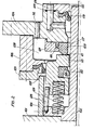
- FIG. 1 shows a liner 2 connected to a propeller hub 1 without the associated shaft, to which the corresponding ring flange parts 3, 4 and 5 are assigned, a sealing housing 6 being arranged between the ring flange parts 3 and 4.
- the seal housing 6 is preceded by a seal 7 in the form of a lip seal on the water inlet side, which seals a chamber 8 formed within the housing 6.
- the chamber 8 is also closed by a mechanical seal consisting of a sliding ring 9 and a counter ring 10.
- the slide ring 9 is firmly connected to the liner 2 by means of a clamping ring 11 with the interposition of a static seal 20.
- the chamber 8 is filled with water, for example, and is pressurized via an inlet channel 12.
- the water may contain additives to increase lubricity or additives. Of course, agents that reduce the growth of algae can also be added.
- a pump 13 is assigned to the supply air channel 12, which is optionally controlled by an outside water pressure transmitter 14 in order to maintain a pressure higher than the outside water pressure in the chamber 8.
- the counter ring 10 is designed as an annular piston and is held under a corresponding pressure via a channel 15.
- a pressure generator 16 is connected to the channel 15. With this controlled contact pressure it is also possible to compensate for changes in length of the shaft.
- a natural lubricating gap 21 is formed between the sliding ring 9 and the counter ring 10.
- the chamber 8 is followed by a further space 17 as a leakage space and closed off with a seal 18 opposite a passage 22 to the actual stern tube.
- This space 17 is connected to a drain channel 19.
- the mechanical seal 9, 10 forms the other seal for the chamber 8.
- the function of the arrangement is that the chamber 8 is at a higher pressure than the existing outside water pressure and thus prevents the ingress of outside water and small amounts of the medium contained are released through the seal 7 to the outside.
- the seal 7 is relieved once and the adjustable mechanical seal 9, 10 and the seal 7 are also kept free of dirt particles.
- the seals 7 and 9, 10 are lubricated.
- the leakage penetrating into space 17 is discharged via drain channel 19.
- control means for the mechanical seal is formed with slide ring 109 and counter ring 110 to maintain an axial pressure by springs 123.
- springs 123 are distributed over the circumference.
- the counter ring 110 is formed from several sub-elements and held together by a spring 126.
- a bracket 127 is assigned to the scope. Otherwise there is a training corresponding to FIG. 1.
- the bushing 102 is also connected to the propeller hub 101.
- a sleeve body 124 is connected to the bushing 102 and forms the receiving space for the springs 123, which are arranged between the sliding ring 109 and the flange of the bushing 102.
- the rotating sliding ring 109 is arranged via a static seal 120 and slidably coupled to the liner via driving bolts 125.
- a housing part 106 for forming a chamber 108 is arranged between fixed flange parts 103, 104 and 105.
- the chamber 108 is connected via a supply line 112 in the aforementioned manner to a pressure generator, not shown.
- the chamber 108 is sealed on the water inlet side by a lip seal 107 and on the other hand by the mechanical seal 109, 110.
- the springs 123 which have a soft spring characteristic, are used to generate an axial pressure, so that the pressing force remains constant even when the counter ring 110 is displaced due to a change in the length of the shafts.
- a natural lubricating gap is formed between the mechanical seal 109, 110.
- the chamber 108 is followed by a leakage space 117, which is closed off with a seal 1.18 opposite a passage 122 to the actual stern tube.
- the leakage space 117 is connected to a drain channel 119. The function of this arrangement is according to FIG. 1.
Landscapes
- Engineering & Computer Science (AREA)
- General Engineering & Computer Science (AREA)
- Mechanical Engineering (AREA)
- Physics & Mathematics (AREA)
- Fluid Mechanics (AREA)
- Chemical & Material Sciences (AREA)
- Combustion & Propulsion (AREA)
- Ocean & Marine Engineering (AREA)
- Sealing Devices (AREA)
- Mechanical Sealing (AREA)
- Sealing With Elastic Sealing Lips (AREA)
Applications Claiming Priority (2)
| Application Number | Priority Date | Filing Date | Title |
|---|---|---|---|
| DE19792925244 DE2925244C2 (de) | 1979-06-22 | 1979-06-22 | Abdichtungsanordnung für Stevenrohranlagen |
| DE2925244 | 1979-06-22 |
Publications (2)
| Publication Number | Publication Date |
|---|---|
| EP0021243A1 true EP0021243A1 (fr) | 1981-01-07 |
| EP0021243B1 EP0021243B1 (fr) | 1982-10-27 |
Family
ID=6073909
Family Applications (1)
| Application Number | Title | Priority Date | Filing Date |
|---|---|---|---|
| EP80103243A Expired EP0021243B1 (fr) | 1979-06-22 | 1980-06-11 | Dispositif d'étanchéité pour les tubes d'étambot de navires |
Country Status (5)
| Country | Link |
|---|---|
| EP (1) | EP0021243B1 (fr) |
| JP (1) | JPS563354A (fr) |
| DD (1) | DD151650A5 (fr) |
| DE (1) | DE2925244C2 (fr) |
| ES (1) | ES492661A0 (fr) |
Cited By (8)
| Publication number | Priority date | Publication date | Assignee | Title |
|---|---|---|---|---|
| EP0671321A1 (fr) * | 1994-03-11 | 1995-09-13 | Ihc Holland N.V. | Joint d'étanchéité avec lubrification de graisse pour les tubes d'étambot |
| CN1037594C (zh) * | 1992-07-09 | 1998-03-04 | 布隆福斯工业有限公司 | 具有两根同心对转轴的船用螺旋桨推进器的密封装置 |
| ITGE20130015A1 (it) * | 2013-02-01 | 2014-08-02 | Microtem Di Mattia Chiodetti E Savi No Larocca Snc | Dispositivo di tenuta meccanica, in particolare per alberi di trasmissione in navi, natanti o simili |
| EP2859950A1 (fr) * | 2013-10-11 | 2015-04-15 | Sandvik Intellectual Property AB | Bague d'étanchéité pour broyeur giratoire |
| CN112923061A (zh) * | 2021-02-04 | 2021-06-08 | 柏燕 | 一种多端面自调控启用的汽轮机轴端密封装置 |
| CN112923060A (zh) * | 2021-02-04 | 2021-06-08 | 柏燕 | 一种多端面自调控启用的汽轮机轴端密封方法 |
| CN112943933A (zh) * | 2021-02-04 | 2021-06-11 | 柏燕 | 一种高可靠性低扭矩零泄漏汽轮机轴端密封装置 |
| CN112943932A (zh) * | 2021-02-04 | 2021-06-11 | 柏燕 | 一种高可靠性零泄漏汽轮机轴端密封方法 |
Families Citing this family (11)
| Publication number | Priority date | Publication date | Assignee | Title |
|---|---|---|---|---|
| JPS56169630A (en) * | 1980-06-03 | 1981-12-26 | Nippon Petrochem Co Ltd | Preparation of fluid for lubricating oil |
| JPS6055599U (ja) * | 1983-09-27 | 1985-04-18 | 三菱重工業株式会社 | 船尾管軸封装置 |
| JPS59165300U (ja) * | 1983-04-21 | 1984-11-06 | 三菱重工業株式会社 | 船尾管軸封装置 |
| NO841210L (no) * | 1983-04-21 | 1984-10-22 | Mitsubishi Heavy Ind Ltd | Tetningsanordning for aksel |
| DE3319040C2 (de) * | 1983-05-26 | 1994-05-19 | Blohm Voss Ag | Abdichtungsanordnung |
| JPS60161298A (ja) * | 1984-02-01 | 1985-08-22 | Mitsubishi Heavy Ind Ltd | スタンチユ−ブシ−ル |
| JPS60161297A (ja) * | 1984-02-02 | 1985-08-22 | Mitsubishi Heavy Ind Ltd | スタンチユ−ブシ−ル |
| JPH0222472U (fr) * | 1988-07-29 | 1990-02-14 | ||
| JPH0515651Y2 (fr) * | 1989-04-27 | 1993-04-23 | ||
| DE19518564A1 (de) * | 1995-05-20 | 1996-11-21 | Klein Schanzlin & Becker Ag | Kreiselpumpe zur Förderung heißer Medien |
| JP6298607B2 (ja) * | 2013-09-19 | 2018-03-20 | 池袋琺瑯工業株式会社 | 軸封構造 |
Citations (10)
| Publication number | Priority date | Publication date | Assignee | Title |
|---|---|---|---|---|
| FR1561443A (fr) * | 1968-02-13 | 1969-03-28 | ||
| DE1953043A1 (de) * | 1968-10-22 | 1970-05-06 | Ferraz & Cie Lucien | Strombruecke fuer Achslager von elektrischen Schienenfahrzeugen |
| US3575426A (en) * | 1968-06-24 | 1971-04-20 | Caterpillar Tractor Co | Pressurized sealing arrangement |
| US3625523A (en) * | 1970-02-13 | 1971-12-07 | Waukesha Bearings Corp | Aft sealing assembly for stern tubes |
| US3726531A (en) * | 1970-12-07 | 1973-04-10 | American Metal Bearing Co | Stern tube seal |
| DD101476A1 (fr) * | 1972-12-22 | 1973-11-12 | ||
| DE2350497A1 (de) * | 1972-12-21 | 1974-06-27 | Rostock Dieselmotoren | Stevenrohrabdichtung |
| CH583391A5 (fr) * | 1973-11-02 | 1976-12-31 | Kraftwerk Union Ag | |
| DE2626048A1 (de) * | 1975-07-07 | 1977-01-27 | Crane Packing Ltd | Hecklager- und -dichtungsanordnung fuer schiffe |
| GB1492965A (en) * | 1975-04-22 | 1977-11-23 | Secr Defence | Shaft seals |
Family Cites Families (8)
| Publication number | Priority date | Publication date | Assignee | Title |
|---|---|---|---|---|
| GB753440A (en) * | 1954-12-13 | 1956-07-25 | Albert Theodore Auguste Gentil | Improvements in or relating to glands for submerged driving or other shafts |
| US3179422A (en) * | 1962-04-10 | 1965-04-20 | Ingersoll Rand Co | Self-compensating shaft seal |
| US3392983A (en) * | 1965-10-22 | 1968-07-16 | Atomic Energy Commission Usa | Safety control device for use with mechanical seals |
| US3291491A (en) * | 1966-01-28 | 1966-12-13 | Watt V Smith | Submarine shaft seal and thrust compensator |
| JPS4831160U (fr) * | 1971-08-23 | 1973-04-16 | ||
| GB1407911A (en) * | 1973-09-26 | 1975-10-01 | Chernykh V P | Rotary shaft end seal for apparatus operatiang under pressure |
| GB1447569A (en) * | 1974-02-27 | 1976-08-25 | Glacier Metal Co Ltd | Seals |
| US3934952A (en) * | 1975-01-24 | 1976-01-27 | Waukesha Bearings Corporation | Leakproof seal for bearings |
-
1979
- 1979-06-22 DE DE19792925244 patent/DE2925244C2/de not_active Expired
-
1980
- 1980-06-11 EP EP80103243A patent/EP0021243B1/fr not_active Expired
- 1980-06-18 JP JP8154080A patent/JPS563354A/ja active Granted
- 1980-06-19 DD DD22198180A patent/DD151650A5/de unknown
- 1980-06-20 ES ES492661A patent/ES492661A0/es active Granted
Patent Citations (10)
| Publication number | Priority date | Publication date | Assignee | Title |
|---|---|---|---|---|
| FR1561443A (fr) * | 1968-02-13 | 1969-03-28 | ||
| US3575426A (en) * | 1968-06-24 | 1971-04-20 | Caterpillar Tractor Co | Pressurized sealing arrangement |
| DE1953043A1 (de) * | 1968-10-22 | 1970-05-06 | Ferraz & Cie Lucien | Strombruecke fuer Achslager von elektrischen Schienenfahrzeugen |
| US3625523A (en) * | 1970-02-13 | 1971-12-07 | Waukesha Bearings Corp | Aft sealing assembly for stern tubes |
| US3726531A (en) * | 1970-12-07 | 1973-04-10 | American Metal Bearing Co | Stern tube seal |
| DE2350497A1 (de) * | 1972-12-21 | 1974-06-27 | Rostock Dieselmotoren | Stevenrohrabdichtung |
| DD101476A1 (fr) * | 1972-12-22 | 1973-11-12 | ||
| CH583391A5 (fr) * | 1973-11-02 | 1976-12-31 | Kraftwerk Union Ag | |
| GB1492965A (en) * | 1975-04-22 | 1977-11-23 | Secr Defence | Shaft seals |
| DE2626048A1 (de) * | 1975-07-07 | 1977-01-27 | Crane Packing Ltd | Hecklager- und -dichtungsanordnung fuer schiffe |
Cited By (13)
| Publication number | Priority date | Publication date | Assignee | Title |
|---|---|---|---|---|
| CN1037594C (zh) * | 1992-07-09 | 1998-03-04 | 布隆福斯工业有限公司 | 具有两根同心对转轴的船用螺旋桨推进器的密封装置 |
| EP0671321A1 (fr) * | 1994-03-11 | 1995-09-13 | Ihc Holland N.V. | Joint d'étanchéité avec lubrification de graisse pour les tubes d'étambot |
| NL9400386A (nl) * | 1994-03-11 | 1995-10-02 | Ihc Holland Nv | Afdichtstelsel voor het afdichten van het naar de schroef gerichte einde van een schroefaskoker van een schip. |
| ITGE20130015A1 (it) * | 2013-02-01 | 2014-08-02 | Microtem Di Mattia Chiodetti E Savi No Larocca Snc | Dispositivo di tenuta meccanica, in particolare per alberi di trasmissione in navi, natanti o simili |
| EP2762758A1 (fr) * | 2013-02-01 | 2014-08-06 | Microtem di Mattia Chiodetti e Savino Larocca SNC | Dispositif d'étanchéité mécanique, en particulier pour des arbres d'entraînement dans des bateaux, des navires ou analogue |
| WO2015051981A1 (fr) * | 2013-10-11 | 2015-04-16 | Sandvik Intellectual Property Ab | Bague d'étanchéité pour concasseur giratoire |
| EP2859950A1 (fr) * | 2013-10-11 | 2015-04-15 | Sandvik Intellectual Property AB | Bague d'étanchéité pour broyeur giratoire |
| CN112923061A (zh) * | 2021-02-04 | 2021-06-08 | 柏燕 | 一种多端面自调控启用的汽轮机轴端密封装置 |
| CN112923060A (zh) * | 2021-02-04 | 2021-06-08 | 柏燕 | 一种多端面自调控启用的汽轮机轴端密封方法 |
| CN112943933A (zh) * | 2021-02-04 | 2021-06-11 | 柏燕 | 一种高可靠性低扭矩零泄漏汽轮机轴端密封装置 |
| CN112943932A (zh) * | 2021-02-04 | 2021-06-11 | 柏燕 | 一种高可靠性零泄漏汽轮机轴端密封方法 |
| CN112943933B (zh) * | 2021-02-04 | 2024-01-12 | 宁波维希密封工业有限公司 | 一种高可靠性低扭矩零泄漏汽轮机轴端密封装置 |
| CN112943932B (zh) * | 2021-02-04 | 2024-01-19 | 灿因工业技术(宁波)有限公司 | 一种高可靠性零泄漏汽轮机轴端密封方法 |
Also Published As
| Publication number | Publication date |
|---|---|
| DE2925244C2 (de) | 1982-09-30 |
| JPH0210000B2 (fr) | 1990-03-06 |
| EP0021243B1 (fr) | 1982-10-27 |
| DD151650A5 (de) | 1981-10-28 |
| ES8103321A1 (es) | 1981-02-16 |
| DE2925244A1 (de) | 1981-01-08 |
| JPS563354A (en) | 1981-01-14 |
| ES492661A0 (es) | 1981-02-16 |
Similar Documents
| Publication | Publication Date | Title |
|---|---|---|
| EP0021243B1 (fr) | Dispositif d'étanchéité pour les tubes d'étambot de navires | |
| DE3045855C2 (fr) | ||
| DE1400425A1 (de) | OEldruckbeaufschlagte Kupplung | |
| DE69612262T2 (de) | Riemenscheibe | |
| DE2101877A1 (de) | Gleitringdichtung | |
| DE2952272A1 (de) | Hochdruckdrehdurchfuehrung | |
| DE102013105890A1 (de) | Drehdurchführung | |
| DE4117097C2 (de) | Abdichtungsvorrichtung für rotierende Wellen, insbesondere Stevenrohrabdichtung für Schiffspropellerwellen | |
| EP3510293A1 (fr) | Mécanisme d'autonettoyage pour cylindre récepteur d'embrayage concentrique pneumatique | |
| DE3605883C2 (fr) | ||
| DE3002804C2 (fr) | ||
| DE3545658A1 (de) | Hydrodynamische bremse fuer ein fahrzeug | |
| DE202014006626U1 (de) | Hydrodynamische Kupplung | |
| DE1193324B (de) | Hydrodynamische Dichtung, insbesondere fuer Pumpen, Kompressoren oder Turbinen | |
| DE102014102633A1 (de) | Drehdurchführung für ein Kraftfahrzeugrad | |
| DE2330750A1 (de) | Schaltkupplung | |
| DE2918418C2 (de) | Stevenrohrabdichtung mit einer Radialdichtung | |
| DE735959C (de) | Lagerung fuer Rollen, insbesondere fuer Tragrollen von Foerderbaendern | |
| AT216294B (fr) | ||
| DE102014218106A1 (de) | Kupplung für ein Kraftfahrzeug mit Drehdurchführungsmodul | |
| EP0947665B1 (fr) | Elément de machine avec remplissage hydraulique, en particulier palier ou arbre tournant | |
| DE102022132774B3 (de) | Nehmerzylinder mit selbstentlüftendem Dichtring | |
| DE3347955C2 (de) | Verstelleinrichtung für Laufschaufeln von Strömungsarbeitsmaschinen axialer Bauart mit senkrecht stehender Welle | |
| AT206760B (de) | Vorrichtung zum Abdichten von Wellenlagern, insbesonder für Doppelgelenkwellen an Fahrzeugen | |
| DE3318163A1 (de) | Verstelleinrichtung fuer laufschaufeln von kreiselmaschinen |
Legal Events
| Date | Code | Title | Description |
|---|---|---|---|
| PUAI | Public reference made under article 153(3) epc to a published international application that has entered the european phase |
Free format text: ORIGINAL CODE: 0009012 |
|
| AK | Designated contracting states |
Designated state(s): FR GB IT NL SE |
|
| 17P | Request for examination filed |
Effective date: 19810124 |
|
| ITF | It: translation for a ep patent filed | ||
| GRAA | (expected) grant |
Free format text: ORIGINAL CODE: 0009210 |
|
| AK | Designated contracting states |
Designated state(s): FR GB IT NL SE |
|
| ET | Fr: translation filed | ||
| REG | Reference to a national code |
Ref country code: FR Ref legal event code: TP |
|
| REG | Reference to a national code |
Ref country code: GB Ref legal event code: 732 |
|
| NLS | Nl: assignments of ep-patents |
Owner name: BLOHM + VOSS AG TE HAMBURG, BONDSREPUBLIEK DUITSLA |
|
| NLT1 | Nl: modifications of names registered in virtue of documents presented to the patent office pursuant to art. 16 a, paragraph 1 |
Owner name: HOWALDTSWERKE-DEUTSCHE WERFT AKTIENGESELLSCHAFT TE |
|
| ITPR | It: changes in ownership of a european patent |
Owner name: CESSIONE;BLOHM + VOSS AG |
|
| ITTA | It: last paid annual fee | ||
| PGFP | Annual fee paid to national office [announced via postgrant information from national office to epo] |
Ref country code: SE Payment date: 19940328 Year of fee payment: 15 |
|
| PGFP | Annual fee paid to national office [announced via postgrant information from national office to epo] |
Ref country code: GB Payment date: 19940602 Year of fee payment: 15 |
|
| PGFP | Annual fee paid to national office [announced via postgrant information from national office to epo] |
Ref country code: FR Payment date: 19940621 Year of fee payment: 15 |
|
| PGFP | Annual fee paid to national office [announced via postgrant information from national office to epo] |
Ref country code: NL Payment date: 19940630 Year of fee payment: 15 |
|
| EAL | Se: european patent in force in sweden |
Ref document number: 80103243.4 |
|
| PG25 | Lapsed in a contracting state [announced via postgrant information from national office to epo] |
Ref country code: GB Effective date: 19950611 |
|
| PG25 | Lapsed in a contracting state [announced via postgrant information from national office to epo] |
Ref country code: SE Effective date: 19950612 |
|
| PG25 | Lapsed in a contracting state [announced via postgrant information from national office to epo] |
Ref country code: NL Effective date: 19960101 |
|
| GBPC | Gb: european patent ceased through non-payment of renewal fee |
Effective date: 19950611 |
|
| PG25 | Lapsed in a contracting state [announced via postgrant information from national office to epo] |
Ref country code: FR Effective date: 19960229 |
|
| NLV4 | Nl: lapsed or anulled due to non-payment of the annual fee |
Effective date: 19960101 |
|
| EUG | Se: european patent has lapsed |
Ref document number: 80103243.4 |
|
| REG | Reference to a national code |
Ref country code: FR Ref legal event code: ST |
|
| PLBE | No opposition filed within time limit |
Free format text: ORIGINAL CODE: 0009261 |
|
| STAA | Information on the status of an ep patent application or granted ep patent |
Free format text: STATUS: NO OPPOSITION FILED WITHIN TIME LIMIT |