EP0021870A1 - Vorrichtung zum Ankoppeln und Auslösen von an Flugkörpern angebrachten Geschossen - Google Patents
Vorrichtung zum Ankoppeln und Auslösen von an Flugkörpern angebrachten Geschossen Download PDFInfo
- Publication number
- EP0021870A1 EP0021870A1 EP80400672A EP80400672A EP0021870A1 EP 0021870 A1 EP0021870 A1 EP 0021870A1 EP 80400672 A EP80400672 A EP 80400672A EP 80400672 A EP80400672 A EP 80400672A EP 0021870 A1 EP0021870 A1 EP 0021870A1
- Authority
- EP
- European Patent Office
- Prior art keywords
- load
- bomb
- rank
- loads
- cylinder
- Prior art date
- Legal status (The legal status is an assumption and is not a legal conclusion. Google has not performed a legal analysis and makes no representation as to the accuracy of the status listed.)
- Granted
Links
Images


Classifications
-
- F—MECHANICAL ENGINEERING; LIGHTING; HEATING; WEAPONS; BLASTING
- F41—WEAPONS
- F41A—FUNCTIONAL FEATURES OR DETAILS COMMON TO BOTH SMALLARMS AND ORDNANCE, e.g. CANNONS; MOUNTINGS FOR SMALLARMS OR ORDNANCE
- F41A19/00—Firing or trigger mechanisms; Cocking mechanisms
- F41A19/58—Electric firing mechanisms
- F41A19/69—Electric contacts or switches peculiar thereto
-
- F—MECHANICAL ENGINEERING; LIGHTING; HEATING; WEAPONS; BLASTING
- F41—WEAPONS
- F41F—APPARATUS FOR LAUNCHING PROJECTILES OR MISSILES FROM BARRELS, e.g. CANNONS; LAUNCHERS FOR ROCKETS OR TORPEDOES; HARPOON GUNS
- F41F3/00—Rocket or torpedo launchers
- F41F3/04—Rocket or torpedo launchers for rockets
- F41F3/052—Means for securing the rocket in the launching apparatus
-
- F—MECHANICAL ENGINEERING; LIGHTING; HEATING; WEAPONS; BLASTING
- F41—WEAPONS
- F41F—APPARATUS FOR LAUNCHING PROJECTILES OR MISSILES FROM BARRELS, e.g. CANNONS; LAUNCHERS FOR ROCKETS OR TORPEDOES; HARPOON GUNS
- F41F3/00—Rocket or torpedo launchers
- F41F3/04—Rocket or torpedo launchers for rockets
- F41F3/06—Rocket or torpedo launchers for rockets from aircraft
Definitions
- the invention relates to a mechanical and electrical coupling device for airborne loads, in particular military loads, such as projectiles. It also relates to projectiles equipped with such devices.
- the invention relates to such a coupling device capable of simultaneously ensuring the hooking and chocking functions of a plurality of charges, projectiles, for example, with a view to carrying them under aircraft, as well as their ejection one by one, starting with the one that is furthest from this aircraft.
- One means of carrying multiple loads under an aircraft consists in attaching an intermediate part, generally called an "adapter", to a polyone, integral with the aircraft, which has a plurality of hooking locations for the loads to be transported. At each of these locations, there are installed the devices allowing, the attachment, the setting, the safety controls, and the ejection of the load. On planes flying at current speeds, a load ejection system. On planes flying at current speeds, an ejection system is generally installed in the adapter to eject the load downwards at a determined speed. At each location, the installation of the load successively requires attachment, then wedging (generally using wedging screws carried by arms), finally electrical or mechanical connection with the safety control members.
- the ejector usually pyrotechnic, is included in the adapter at each location. It is actuated by a powder impeller. Because on these adapters, it is only possible to hang and eject a load per location, a mission requiring the successive release of a large number of loads (for example a release in a chain) poses problems considerable if the number of pylons is not sufficient or if some should be reserved for other uses.
- the object of the present invention is to overcome these drawbacks and relates to a coupling device integral with each of the loads comprising a combination of means cooperating with each other to accomplish the following four essential functions, namely: attachment of one load to another , the setting of each of the charges thus attached to the previous one, the electrical connection necessary for the implementation of the sequencers equipping these charges and the ejection one after the other of these charges thus superimposed, starting with the most charged away from the adapter.
- the present invention relates more precisely to a mechanical and electrical coupling device for loads, in particular military, with a view to carrying them under aircraft, characterized in that it comprises a combination of attachment means, wedging, electrical connection and ejection ensuring the mechanical attachment of a plurality of loads of successive ranks n, (n - 1), (n - 2) ...
- FIGS. 2a and 2b each represent a detail of FIG. 1.
- the first and the second bomb 1 and 2 are respectively called carrier bomb of rank (n - 1) and bomb carried of rank (n).
- the number (n) depends on the resistance criteria of the materials and the mechanical stresses involved. Only part of these bombs is represented with the exception of the front part (Av) and the rear part (Ar).
- the coupling device according to the invention is generally referenced 20.
- It essentially comprises a combination of mechanical attachment and setting means, electrical means for transferring the control signals, and ejection means. It is an integral part of the body of the load (in the example described). But it can be independent and is then connected to it solidly by any means that does not compromise the aerodynamic qualities of the assembly. In all cases, it is positioned near the center of gravity of the load.
- the hooking and wedging means essentially comprise a connecting element 70 connecting together a male part 3 and a female part 6.
- the first part in an exemplary embodiment comprises a pivotable cylinder 4 carrying balls 5 and a system of conductive pads 83 ( Figure 2b) whose function will be described later.
- the second part 6, called the fixed base comprises, as shown in FIG. 2a, a cavity 7 delimited by a flange 8 interrupted by cells 9. It also comprises a set of mobile pads good conductors of electricity 82 intended to cooperate, as will be explained below, with the fixed pads 83 of the pivotable cylinder.
- the number and the arrangement of the balls 5 at the periphery of the attachment cylinder 4 on the one hand, the distribution of the cells 9 in the cavity 7 on the other hand, are such that at first the attachment cylinder of the bomb carried having rotated by a certain angle, can be introduced inside the cavity 7 of the bomb 2 carried, the balls then coinciding with the cells 9 along which they can slide and in a second time, the cylinder 4 ball holder 5 having returned to its initial position, the balls 5 are supported by the rim 8 of the cavity 7 then playing a supporting role for the balls 5.
- the attachment between the carrier bomb 1 and the carrier bomb 2 is thus assured.
- First means 10 are provided for rotation of the attachment cylinder 4, ball holder 5, while second means 11 ensure the displacement of wedging wedges 12 intended to cooperate with the oblique surfaces of a support 13.
- the bomb carried is then wedged in three directions, thanks to the combined action of the connection by the attachment cylinder, wedging wedges and first supports 13 and second fixed supports 15 whose shape substantially matches that of the body the bomb.
- a housing 90 formed in a bracket 111 is provided for receiving a key whose rotation will cause that of the cylinder 4 ball holder 5.
- Figures 3 and 4 schematically show, in section and from above the means 10 and 11 respectively intended to ensure the movement of the attachment cylinder 4 carrying the balls 5 and that of the wedging wedges 12. These means are shown in these figures in the configuration corresponding to the so-called rest state, that is to say that which corresponds to the storage of the bombs before hanging for the purpose of carrying.
- the carrier bomb 1 on which will be attached a first bomb 2 carried is equipped with a device according to the invention.
- a finger 23 coordinates the movements of the upper slide 21 and of the slide 22 and is integral with a second slide called the lower slide referenced 24 attached to the casing 25 by means of studs 26 and 260 allowing its sliding between the casing and the head of these studs.
- This slider 24 has a light 27 which allows the slider 24 to slide at the level of the central stud 260 ( Figure 3) all along the light 27.
- This slider 24 is also made integral with the two wedging wedges 12 which will follow its movement but which are returned to the initial so-called rest position by means of a return spring 29.
- the device according to the invention is an integral part of the bomb, that is to say that the envelope 25 is confused with the shell (or body) of the bomb, but as has already been said, such a device can be produced in the form of an independent part.
- the slide 21 and the slide 22 each have a guide path 31 and 32 for the finger 23. They have the same profile which in the state of rest, however, does not overlap. Thus, the finger 23 is flush with the guide path 31 of the slide 21.
- the profile of this guide path 31 in plan view is not shown but it is the same as the profile of the guide path 32 of the second slide which is shown in Figure 4.
- This Figure 4 has been shown, seen from above, in a configuration where the upper slide 21 has been removed, this to facilitate description and understanding.
- the slide 22 has a second longitudinal guide path 33.
- the slide 21 and the slide 22 are held together by lugs 330 allowing relative movement in two parallel planes of one and on the other of these parts 21 and 22.
- the attachment of the first carrier bomb 1 with the second bomb bomb 2 is produced in particular thanks to the cooperation of this slide and this slide whose movement is ensured by the finger 23 as is now described and illustrated by means of FIGS. 5 and 6.
- Figure 5 shows, in sectional view, the position of the various elements constituting the attachment and wedging system itself, namely the slide and the slide 21 and 22, the finger 23 guided by the guide tracks 31, 32 , 33.
- the springs 29 and the wedging wedges 12, these elements being driven in movement by means of the key 102, when the key is in a position such that the finger 23 is unlocked.
- Figure 6 is a plan view of the same attachment and wedging system in an intermediate configuration according to the unlocking configuration and before locking, shown in the previous figure, during which the finger 23 guided in the curved guide paths 31 and 32 then placed in coincidence, rotates the slide 22 and the cylinder 4 which is integral with it.
- the key 100 which includes a control lever 101 and a bolt 102 capable of applying a force on the upper slide 21 on a curved part of the latter called, striker 103 by analogy with the bolt 102.
- striker 103 As and as the operator presses the bolt 102 of the key 100 on the keeper 103 of the upper slide 21 in the direction of the arrow 104 (FIG. 5), the set of upper and lower slides 21 and 24 moves in the direction of the arrow 105.
- the finger 23 first guided by the longitudinal guide path 33 driving the lower slide 24 until the guide path 32 coincides with the guide path 31 of the upper slide 21, paths whose profiles are l both identical and curved as mentioned above.
- FIG. 6 schematically represents an intermediate configuration clearly showing the angle oC already existing between the longitudinal axis AB of the device and the longitudinal axis A'B 'of the upper slide and slide system.
- the receding wedging wedges are applied to the support 13, thus ensuring the wedging of the carried bomb maintained, moreover, both by the attachment system and the fixed support with curved contact 15. It is immobilized in all directions without the need for more or less sophisticated timing adjustments.
- FIG. 7a the upper slide and the slide occupy a position corresponding to the configuration shown in FIG. 1.
- the key 100 is inserted into the housing 90 provided for this purpose.
- the upper slide 21 and more particularly the keeper 103 of this slide on which the bolt 102 of the key 100 must come to bear is extended by a spout 110 In the rest position ( Figure 7a), the key can be inserted or removed without difficulty, the housing 90 not being obscured by this beak 110.
- FIG. 7a the key can be inserted or removed without difficulty, the housing 90 not being obscured by this beak 110.
- such a device also comprises a connecting element (reference 70 in FIG. 1) between the cylinder 4 with ball bearing and the cavity 7, an element containing the electrical transfer members on the one hand and the ejection means on the other hand.
- FIG. 8 schematically illustrates an exemplary embodiment of such a connecting element 70.
- the two charges in the example describing the bomb 1 carrier and the bomb 2 carried, are shown.
- Any female part 6 referenced 6a in the case of the bomb 1 and 6b in the case of the bomb 2 comprises a plurality of movable studs 82a and 82b. In the example described, there are four of them distributed uniformly over a ring 85a and 85b, two of which are only visible in FIG. 9.
- Fixed contact pads 83b (the fixed pads belonging to the bomb 1 only appear not appear in Figure 8) in the same number as the movable contact pads 82a are provided and distributed in the same way on a ring belonging to the cylinder 4 ball holder.
- the arrangement of these movable pads and these fixed pads are such that they cooperate with each other to ensure, when they are applied respectively against each other, good electrical contact.
- the crown 85a belongs to the cavity 6a of the carrier bomb 1 and the movable studs 82a (symbolized by the presence of the springs 850 come to bear on the fixed contacts 83b of the ball-bearing cylinder 5 of the bomb carried 2
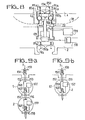
- the connecting element 70 also includes a sequencer 159 which receives the electrical orders emitted by the pilot of the aircraft and leading to the adapter attached to the pylon of this aircraft The orders pass as follows, illustrated diagrammatically by means of FIGS. 9a and 9b.
- the sequencer 157 is off and therefore receives no pulse in this sequence. As a result, only the sequencer 159 will be activated and able to deliver the control signals ensuring the smooth running of the rest of the programmed operations. In the case where only one bomb is still attached, the contact 160 is on the contrary in the closed position and this signal is therefore applied to sequencer 157 which can thus play its role. In the example described as mentioned above, there are four fixed and movable studs. Three of these pads are used to control the sequencers and the fourth to trigger a pyrotechnic charge 170 as shown in FIG. 8.
- the electrical transfer circuit intended to control the firing of this pyrotechnic charge 170 follows the same process as that which has just been described for the various sequencers: namely that only the pyrotechnic charge of the lowest bomb (bomb of rank n) is ignited; the bomb of rank (n - 1) being able to be ignited only when the bomb of rank (n) was itself ejected.
- the firing of a pyrotechnic charge for example the charge 170 of FIG.
- the invention applies in particular to weapons systems requiring the successive dropping of a large number of military charges such as bombs or various projectiles.
Landscapes
- Engineering & Computer Science (AREA)
- General Engineering & Computer Science (AREA)
- Aviation & Aerospace Engineering (AREA)
- Filling Or Discharging Of Gas Storage Vessels (AREA)
- Toys (AREA)
- Details Of Connecting Devices For Male And Female Coupling (AREA)
- Automatic Assembly (AREA)
- Load-Engaging Elements For Cranes (AREA)
- Coupling Device And Connection With Printed Circuit (AREA)
Priority Applications (1)
| Application Number | Priority Date | Filing Date | Title |
|---|---|---|---|
| AT80400672T ATE5806T1 (de) | 1979-06-07 | 1980-05-14 | Vorrichtung zum ankoppeln und ausloesen von an flugkoerpern angebrachten geschossen. |
Applications Claiming Priority (2)
| Application Number | Priority Date | Filing Date | Title |
|---|---|---|---|
| FR7914591A FR2458459A1 (fr) | 1979-06-07 | 1979-06-07 | Dispositif d'accouplement mecanique et electrique pour charges, notamment militaires |
| FR7914591 | 1979-06-07 |
Publications (2)
| Publication Number | Publication Date |
|---|---|
| EP0021870A1 true EP0021870A1 (de) | 1981-01-07 |
| EP0021870B1 EP0021870B1 (de) | 1984-01-11 |
Family
ID=9226333
Family Applications (1)
| Application Number | Title | Priority Date | Filing Date |
|---|---|---|---|
| EP80400672A Expired EP0021870B1 (de) | 1979-06-07 | 1980-05-14 | Vorrichtung zum Ankoppeln und Auslösen von an Flugkörpern angebrachten Geschossen |
Country Status (18)
| Country | Link |
|---|---|
| US (1) | US4350074A (de) |
| EP (1) | EP0021870B1 (de) |
| JP (1) | JPS55164598A (de) |
| AR (1) | AR225635A1 (de) |
| AT (1) | ATE5806T1 (de) |
| BR (1) | BR8003608A (de) |
| CA (1) | CA1153619A (de) |
| DE (1) | DE3066079D1 (de) |
| DK (1) | DK155810C (de) |
| ES (1) | ES492130A0 (de) |
| FI (1) | FI65201C (de) |
| FR (1) | FR2458459A1 (de) |
| IL (1) | IL60229A (de) |
| IN (1) | IN154505B (de) |
| NO (1) | NO153466C (de) |
| PT (1) | PT71343A (de) |
| TR (1) | TR21189A (de) |
| ZA (1) | ZA803382B (de) |
Cited By (1)
| Publication number | Priority date | Publication date | Assignee | Title |
|---|---|---|---|---|
| FR2786860A1 (fr) * | 1998-12-08 | 2000-06-09 | Agency Defense Dev | Dispositif de retenue et de deverrouillage d'un projectile utilisant une sphere rigide |
Families Citing this family (7)
| Publication number | Priority date | Publication date | Assignee | Title |
|---|---|---|---|---|
| US4478127A (en) * | 1982-09-23 | 1984-10-23 | The United States Of America As Represented By The Secretary Of The Navy | Bomb saddle interface module |
| US5465925A (en) * | 1994-05-27 | 1995-11-14 | United Technologies Corporation | Automatic release of a load from a helicopter external cargo suspension system |
| US6769830B1 (en) * | 2000-07-05 | 2004-08-03 | Lockheed Martin Corporation | Connector assembly |
| US6530718B2 (en) | 2001-01-30 | 2003-03-11 | Lockheed Martin Corporation | Connector assembly |
| US9091506B2 (en) | 2013-02-27 | 2015-07-28 | Amphenol Corporation | Float support member for rocket launcher |
| US8864509B2 (en) | 2013-02-27 | 2014-10-21 | Amphenol Corporation | Rocket launcher connector assembly |
| RU2740324C1 (ru) * | 2020-06-30 | 2021-01-13 | Акционерное общество "Вятское машиностроительное предприятие "АВИАТЕК" | Держатель балочный многозамковый универсальный вертолетный |
Citations (7)
| Publication number | Priority date | Publication date | Assignee | Title |
|---|---|---|---|---|
| FR1052914A (fr) * | 1952-02-20 | 1954-01-28 | Dispositif pour le maintien de bombes-fusées sur-un avion | |
| FR1063909A (fr) * | 1951-06-26 | 1954-05-10 | Bofors Ab | Dispositif de suspension pour fusée |
| FR1127307A (fr) * | 1954-07-09 | 1956-12-13 | Bofors Ab | Dispositif de verrouillage pour projectiles en grappes |
| FR1211583A (fr) * | 1957-08-27 | 1960-03-17 | Brevets Aero Mecaniques | Perfectionnements apportés aux roquettes devant pouvoir être suspendues par grappes à un engin de lancement, notamment à un aérodyne |
| FR1282991A (fr) * | 1960-03-07 | 1962-01-27 | Brevets Aero Mecaniques | Perfectionnements apportés aux ensembles comportant plusieurs roquettes supportéesen série par un engin de lancement |
| US3787012A (en) * | 1973-02-05 | 1974-01-22 | Mc Donnell Douglas Corp | Internal ejector mechanism for stacked sequentially releasable separable units |
| US3887150A (en) * | 1973-02-05 | 1975-06-03 | Mc Donnell Douglas Corp | Internal ejector mechanism |
Family Cites Families (6)
| Publication number | Priority date | Publication date | Assignee | Title |
|---|---|---|---|---|
| US3041937A (en) * | 1952-10-09 | 1962-07-03 | John F Toomey | Rocket control system |
| US2939102A (en) * | 1955-11-04 | 1960-05-31 | Northrop Corp | Self-aligning quick disconnect plug |
| US3010752A (en) * | 1957-11-29 | 1961-11-28 | Geffner Ted | Ejection bolt mechanism |
| GB859458A (en) * | 1959-04-22 | 1961-01-25 | Erik Waldemar Broden | Improvements in or relating to release mechanism for bombs and the like |
| US4026188A (en) * | 1975-12-24 | 1977-05-31 | Sanders Associates, Inc. | Modular buoy system |
| GB1529087A (en) * | 1976-04-30 | 1978-10-18 | Westland Aircraft Ltd | Store ejector release units |
-
1979
- 1979-06-07 FR FR7914591A patent/FR2458459A1/fr active Granted
-
1980
- 1980-05-14 AT AT80400672T patent/ATE5806T1/de not_active IP Right Cessation
- 1980-05-14 DE DE8080400672T patent/DE3066079D1/de not_active Expired
- 1980-05-14 EP EP80400672A patent/EP0021870B1/de not_active Expired
- 1980-05-20 US US06/151,587 patent/US4350074A/en not_active Expired - Lifetime
- 1980-06-03 PT PT71343A patent/PT71343A/pt unknown
- 1980-06-04 JP JP7539980A patent/JPS55164598A/ja active Granted
- 1980-06-04 IL IL60229A patent/IL60229A/xx unknown
- 1980-06-04 ES ES492130A patent/ES492130A0/es active Granted
- 1980-06-05 TR TR21189A patent/TR21189A/xx unknown
- 1980-06-05 CA CA000353436A patent/CA1153619A/fr not_active Expired
- 1980-06-06 FI FI801826A patent/FI65201C/fi not_active IP Right Cessation
- 1980-06-06 AR AR281319A patent/AR225635A1/es active
- 1980-06-06 NO NO801704A patent/NO153466C/no unknown
- 1980-06-06 DK DK245280A patent/DK155810C/da not_active IP Right Cessation
- 1980-06-06 ZA ZA00803382A patent/ZA803382B/xx unknown
- 1980-06-09 BR BR8003608A patent/BR8003608A/pt not_active IP Right Cessation
- 1980-07-15 IN IN521/DEL/80A patent/IN154505B/en unknown
Patent Citations (7)
| Publication number | Priority date | Publication date | Assignee | Title |
|---|---|---|---|---|
| FR1063909A (fr) * | 1951-06-26 | 1954-05-10 | Bofors Ab | Dispositif de suspension pour fusée |
| FR1052914A (fr) * | 1952-02-20 | 1954-01-28 | Dispositif pour le maintien de bombes-fusées sur-un avion | |
| FR1127307A (fr) * | 1954-07-09 | 1956-12-13 | Bofors Ab | Dispositif de verrouillage pour projectiles en grappes |
| FR1211583A (fr) * | 1957-08-27 | 1960-03-17 | Brevets Aero Mecaniques | Perfectionnements apportés aux roquettes devant pouvoir être suspendues par grappes à un engin de lancement, notamment à un aérodyne |
| FR1282991A (fr) * | 1960-03-07 | 1962-01-27 | Brevets Aero Mecaniques | Perfectionnements apportés aux ensembles comportant plusieurs roquettes supportéesen série par un engin de lancement |
| US3787012A (en) * | 1973-02-05 | 1974-01-22 | Mc Donnell Douglas Corp | Internal ejector mechanism for stacked sequentially releasable separable units |
| US3887150A (en) * | 1973-02-05 | 1975-06-03 | Mc Donnell Douglas Corp | Internal ejector mechanism |
Cited By (1)
| Publication number | Priority date | Publication date | Assignee | Title |
|---|---|---|---|---|
| FR2786860A1 (fr) * | 1998-12-08 | 2000-06-09 | Agency Defense Dev | Dispositif de retenue et de deverrouillage d'un projectile utilisant une sphere rigide |
Also Published As
| Publication number | Publication date |
|---|---|
| CA1153619A (fr) | 1983-09-13 |
| TR21189A (tr) | 1983-12-06 |
| FR2458459A1 (fr) | 1981-01-02 |
| ES8201086A1 (es) | 1981-11-01 |
| EP0021870B1 (de) | 1984-01-11 |
| FI65201B (fi) | 1983-12-30 |
| NO153466B (no) | 1985-12-16 |
| PT71343A (fr) | 1980-07-01 |
| DK155810B (da) | 1989-05-16 |
| DK155810C (da) | 1989-10-02 |
| ES492130A0 (es) | 1981-11-01 |
| BR8003608A (pt) | 1981-01-05 |
| FI65201C (fi) | 1984-04-10 |
| FR2458459B1 (de) | 1983-02-18 |
| IN154505B (de) | 1984-11-03 |
| US4350074A (en) | 1982-09-21 |
| JPH0362599B2 (de) | 1991-09-26 |
| NO153466C (no) | 1986-03-26 |
| FI801826A7 (fi) | 1980-12-08 |
| ATE5806T1 (de) | 1984-01-15 |
| DK245280A (da) | 1980-12-08 |
| AR225635A1 (es) | 1982-04-15 |
| ZA803382B (en) | 1981-06-24 |
| DE3066079D1 (en) | 1984-02-16 |
| NO801704L (no) | 1980-12-08 |
| JPS55164598A (en) | 1980-12-22 |
| IL60229A (en) | 1982-09-30 |
Similar Documents
| Publication | Publication Date | Title |
|---|---|---|
| EP0619628B1 (de) | Elektrische Verbinder insbesondere Verbinder zum Laden von Akkus | |
| FR2955653A1 (fr) | Dispositif de deploiement simultane de gouvernes d'un projectile | |
| EP0133082A1 (de) | Sicherheitseinrichtung zum Öffnen einer Flugzeugtür die sich im Fall von Überdruck innerhalb des Flugzeugs nach aussen öffnet und eine so ausgestattete Tür | |
| EP0021870B1 (de) | Vorrichtung zum Ankoppeln und Auslösen von an Flugkörpern angebrachten Geschossen | |
| EP0324688A1 (de) | Von der Schulter abzufeuernder Raketenwerfer | |
| EP0562364A1 (de) | Automatische oder halbautomatische Schusswaffe | |
| EP0067731B1 (de) | Vorrichtung zum Befestigen von einem am Flugzeug angeordneten Element, insbesondere von einer Leuchtkörperabschusseinrichtung | |
| EP0296936A1 (de) | Antriebsvorrichtung zum schnellen und geregelten Trennen von zwei miteinander verbundenen Teilen | |
| EP0061398A1 (de) | Verfahren und Vorrichtung zum Speichern und Ausklinken von zylindrischen Objekten in Fahrzeugen | |
| EP0296010A1 (de) | Trage- und Abwurfvorrichtung für Lasten an einem Flugzeug, insbesondere für Flugkörper | |
| CA3192682A1 (fr) | Dispositif de convoyage et de largage a indicateur de presence de cartouche | |
| FR2729117A1 (fr) | Procede de pilotage d'un engin et engin permettant la mise en oeuvre du procede | |
| EP0488872A1 (de) | Vorrichtung zum zeitweisen Halten eines Objekts an einem Träger mit einer einteiligen Halterungshülse | |
| EP0641989A1 (de) | Magazin formende Munition zum Verschiessen elektromagnetischer Düppel | |
| EP0684442B1 (de) | Zufuhrvorrichtung für Munition für automatische Waffen | |
| EP2511991A1 (de) | Elektrische Kontaktherstellungsvorrichtung zwischen einer Plattform und einem Gerät, Abschussanlage und entsprechendes Verfahren | |
| FR2724907A1 (fr) | Lanceur de leurres electromagnetiques a ejection differee | |
| EP0756151B1 (de) | Vorrichtung zum Zünden einer Treibladung für eine aus einem Trägergeschoss geworfene Submunition | |
| EP0597750B1 (de) | Gerät zum Halten und Auswerfen eines Objekts bezüglich eines Trägers, mit einer kontrollierten Ablauffolge | |
| FR2679990A1 (fr) | Systeme d'obturation de bouche a feu d'un tube de canon. | |
| FR2691797A1 (fr) | Système de sécurité et d'armement pour sous-munition, en particulier pour sous-munition embarquée dans un obus cargo. | |
| EP0661514B1 (de) | Waffe mit bewegbaren Verschlussstücken | |
| EP0577472B1 (de) | Pfandvorrichtung und damit versehene an seinesgleichen schachtelbare Einkaufswagen | |
| EP0067732B1 (de) | Am Flugzeug angeordnete Flugkörper-Abschusseinrichtung mit rückstellbarer Sicherheit | |
| FR2726637A1 (fr) | Dispositif pour refouler une munition dans le tube d'un canon, et pour effectuer l'operation inverse |
Legal Events
| Date | Code | Title | Description |
|---|---|---|---|
| PUAI | Public reference made under article 153(3) epc to a published international application that has entered the european phase |
Free format text: ORIGINAL CODE: 0009012 |
|
| AK | Designated contracting states |
Designated state(s): AT BE CH DE GB IT LI LU NL SE |
|
| 17P | Request for examination filed |
Effective date: 19810117 |
|
| ITF | It: translation for a ep patent filed | ||
| GRAA | (expected) grant |
Free format text: ORIGINAL CODE: 0009210 |
|
| AK | Designated contracting states |
Designated state(s): AT BE CH DE GB IT LI LU NL SE |
|
| REF | Corresponds to: |
Ref document number: 5806 Country of ref document: AT Date of ref document: 19840115 Kind code of ref document: T |
|
| REF | Corresponds to: |
Ref document number: 3066079 Country of ref document: DE Date of ref document: 19840216 |
|
| PLBE | No opposition filed within time limit |
Free format text: ORIGINAL CODE: 0009261 |
|
| STAA | Information on the status of an ep patent application or granted ep patent |
Free format text: STATUS: NO OPPOSITION FILED WITHIN TIME LIMIT |
|
| 26N | No opposition filed | ||
| PGFP | Annual fee paid to national office [announced via postgrant information from national office to epo] |
Ref country code: CH Payment date: 19930413 Year of fee payment: 14 |
|
| PGFP | Annual fee paid to national office [announced via postgrant information from national office to epo] |
Ref country code: SE Payment date: 19930419 Year of fee payment: 14 |
|
| PGFP | Annual fee paid to national office [announced via postgrant information from national office to epo] |
Ref country code: GB Payment date: 19930422 Year of fee payment: 14 |
|
| PGFP | Annual fee paid to national office [announced via postgrant information from national office to epo] |
Ref country code: BE Payment date: 19930503 Year of fee payment: 14 |
|
| PGFP | Annual fee paid to national office [announced via postgrant information from national office to epo] |
Ref country code: LU Payment date: 19930518 Year of fee payment: 14 |
|
| PGFP | Annual fee paid to national office [announced via postgrant information from national office to epo] |
Ref country code: AT Payment date: 19930528 Year of fee payment: 14 |
|
| ITTA | It: last paid annual fee | ||
| PGFP | Annual fee paid to national office [announced via postgrant information from national office to epo] |
Ref country code: NL Payment date: 19930531 Year of fee payment: 14 |
|
| EPTA | Lu: last paid annual fee | ||
| PG25 | Lapsed in a contracting state [announced via postgrant information from national office to epo] |
Ref country code: LU Free format text: LAPSE BECAUSE OF NON-PAYMENT OF DUE FEES Effective date: 19940514 Ref country code: GB Effective date: 19940514 Ref country code: AT Effective date: 19940514 |
|
| PG25 | Lapsed in a contracting state [announced via postgrant information from national office to epo] |
Ref country code: SE Effective date: 19940515 |
|
| PG25 | Lapsed in a contracting state [announced via postgrant information from national office to epo] |
Ref country code: LI Effective date: 19940531 Ref country code: CH Effective date: 19940531 Ref country code: BE Effective date: 19940531 |
|
| BERE | Be: lapsed |
Owner name: THOMSON-BRANDT Effective date: 19940531 |
|
| PG25 | Lapsed in a contracting state [announced via postgrant information from national office to epo] |
Ref country code: NL Effective date: 19941201 |
|
| GBPC | Gb: european patent ceased through non-payment of renewal fee |
Effective date: 19940514 |
|
| NLV4 | Nl: lapsed or anulled due to non-payment of the annual fee | ||
| EUG | Se: european patent has lapsed |
Ref document number: 80400672.4 Effective date: 19941210 |
|
| REG | Reference to a national code |
Ref country code: CH Ref legal event code: PL |
|
| EUG | Se: european patent has lapsed |
Ref document number: 80400672.4 |
|
| PGFP | Annual fee paid to national office [announced via postgrant information from national office to epo] |
Ref country code: DE Payment date: 19970417 Year of fee payment: 18 |
|
| PG25 | Lapsed in a contracting state [announced via postgrant information from national office to epo] |
Ref country code: DE Free format text: LAPSE BECAUSE OF NON-PAYMENT OF DUE FEES Effective date: 19990302 |